

Page 1
Operating Instructions
Fieldgate FXA720
Ethernet/PROFIBUS DP gateway with Web server
8
BA030S/04/en/07.07
Product Version 2. 0 0. xx
56004856
Page 2

Page 3

Fieldgate FXA720
Table of Contents
Revision History . . . . . . . . . . . . . . . . . . . . . . . . . . . 3
Software Compatibility . . . . . . . . . . . . . . . . . . . . . . 3
Registered Trademarks . . . . . . . . . . . . . . . . . . . . . . . 3
1 Safety
1.1 Designated use . . . . . . . . . . . . . . . . . . . . . . . . . . . . 3
1.2 Installation, commissioning and operation . . . . . . . . 3
1.3 Operational safety . . . . . . . . . . . . . . . . . . . . . . . . . . 3
1.4 Technical improvement . . . . . . . . . . . . . . . . . . . . . . 3
1.5 Declaration of conformity . . . . . . . . . . . . . . . . . . . . 4
1.6 Writing conventions . . . . . . . . . . . . . . . . . . . . . . . . 5
1.7 Drawing conventions . . . . . . . . . . . . . . . . . . . . . . . 6
2 Identification
2.1 Device designation . . . . . . . . . . . . . . . . . . . . . . . . . 7
2.2 Scope of delivery . . . . . . . . . . . . . . . . . . . . . . . . . . . 7
2.3 Licensing agreement . . . . . . . . . . . . . . . . . . . . . . . . 7
3 Function and System Design
3.1 Function . . . . . . . . . . . . . . . . . . . . . . . . . . . . . . . . . 8
3.2 Design . . . . . . . . . . . . . . . . . . . . . . . . . . . . . . . . . . 9
3.2.1 Connectors . . . . . . . . . . . . . . . . . . . . . . . . . 9
3.2.2 Display elements (LEDs) . . . . . . . . . . . . . . . 9
3.3 System architecture . . . . . . . . . . . . . . . . . . . . . . . . 10
3.4 System requirements . . . . . . . . . . . . . . . . . . . . . . . 12
4 Hardware Installation
4.1 Mounting . . . . . . . . . . . . . . . . . . . . . . . . . . . . . . . 13
4.2 Wiring . . . . . . . . . . . . . . . . . . . . . . . . . . . . . . . . . 14
4.2.1 Power supply . . . . . . . . . . . . . . . . . . . . . . 14
4.2.2 Communication ports . . . . . . . . . . . . . . . . 15
. . . . . . . . . . . . . . . . . . . . . . . . . . . . . . .
. . . . . . . . . . . . . . . . . . . . . . . .
. . . . . . . . . .
. . . . . . . . . . . . . . .
13
6 Configuring the Web Server
6.1 Logging on . . . . . . . . . . . . . . . . . . . . . . . . . . . . . . 29
6.2 User interface . . . . . . . . . . . . . . . . . . . . . . . . . . . . 30
3
7
8
6.2.1 Menu bar . . . . . . . . . . . . . . . . . . . . . . . . . 30
6.2.2 Navigation bar . . . . . . . . . . . . . . . . . . . . . . 31
6.2.3 Information & Configuration pages . . . . . . . 32
6.3 Fieldgate location page . . . . . . . . . . . . . . . . . . . . . . 33
6.4 Security setup . . . . . . . . . . . . . . . . . . . . . . . . . . . . 34
6.5 Network setup . . . . . . . . . . . . . . . . . . . . . . . . . . . . 35
6.5.1 Ethernet . . . . . . . . . . . . . . . . . . . . . . . . . . 35
6.5.2 E-mail . . . . . . . . . . . . . . . . . . . . . . . . . . . . 36
6.5.3 Time server . . . . . . . . . . . . . . . . . . . . . . . . 37
6.6 PROFIBUS setup . . . . . . . . . . . . . . . . . . . . . . . . . . 38
6.6.1 Communication settings . . . . . . . . . . . . . . 38
6.6.2 Scan settings . . . . . . . . . . . . . . . . . . . . . . . 40
6.6.3 Live list . . . . . . . . . . . . . . . . . . . . . . . . . . . 40
6.7 Overview of selected devices . . . . . . . . . . . . . . . . . 41
6.7.1 Device detail parameters . . . . . . . . . . . . . . 42
6.7.2 E-mail on alarm . . . . . . . . . . . . . . . . . . . . . 42
6.7.3 Expert mode for Slot/Index configuration . 43
. . . . . . . . .
7 Viewing Information (User Mode)
7.1 Logging on . . . . . . . . . . . . . . . . . . . . . . . . . . . . . . 44
7.2 Live list . . . . . . . . . . . . . . . . . . . . . . . . . . . . . . . . . 45
7.3 Overview of selected devices . . . . . . . . . . . . . . . . . 46
7.4 Fieldgate information . . . . . . . . . . . . . . . . . . . . . . . 47
7.5 XML export . . . . . . . . . . . . . . . . . . . . . . . . . . . . . . 48
7.6 Other view functions . . . . . . . . . . . . . . . . . . . . . . . 49
7.6.1 Refresh function . . . . . . . . . . . . . . . . . . . . 49
7.6.2 Endress+Hauser function . . . . . . . . . . . . . . 49
8 Firmware Update
. . . . . . . . . . . . . . . . . . .
. . .
29
44
50
5 Getting Started
5.1 Preparing for installation . . . . . . . . . . . . . . . . . . . . 16
5.1.1 Checking the system requirements . . . . . . 16
5.1.2 Installing the documentation . . . . . . . . . . . 17
5.1.3 Adobe Acrobat Reader . . . . . . . . . . . . . . . . 17
5.2 Establishing communication . . . . . . . . . . . . . . . . . 18
5.2.1 Making initial contact . . . . . . . . . . . . . . . . 18
5.2.2 Changing the Fieldgate address . . . . . . . . . 20
5.3 Installing FXA720 PROFIBUS Driver . . . . . . . . . . . 21
5.3.1 Installing the driver . . . . . . . . . . . . . . . . . . 21
5.3.2 Configuring the driver . . . . . . . . . . . . . . . . 23
5.3.3 Setting PROFIBUS DP bus parameters
in FieldCare . . . . . . . . . . . . . . . . . . . . . . . 26
5.3.4 Setting PROFIBUS DP bus parameters
in P View . . . . . . . . . . . . . . . . . . . . . . . . . 27
5.4 Modifying, repairing or removing the application . . 28
5.4.1 Fieldgate FXA720 PROFIBUS Driver . . . . . 28
5.4.2 Fieldgate FXA720 documentation . . . . . . . 28
Endress+Hauser 1
. . . . . . . . . . . . . . . . . . . . . .
16
9 Trouble-Shooting
9.1 Problems and remedies . . . . . . . . . . . . . . . . . . . . . 51
9.2 FAQ - Frequently Asked Questions . . . . . . . . . . . . . 51
9.3 Troubleshooting on no connection . . . . . . . . . . . . . 52
10 Accessories
10.1 E+H power supply units . . . . . . . . . . . . . . . . . . . . 53
11 Technical Data
12 Appendix
12.1 Changing the Internet address (Windows 2000) . . . 55
12.2 XML data elements . . . . . . . . . . . . . . . . . . . . . . . . 57
12.3 PROFIBUS bus parameter ranges . . . . . . . . . . . . . . 58
. . . . . . . . . . . . . . . . . . . . . . . . . .
Index . . . . . . . . . . . . . . . . . . . . . . . . . 59
. . . . . . . . . . . . . . . . . . .
. . . . . . . . . . . . . . . . . . . . . . . .
. . . . . . . . . . . . . . . . . . . . .
51
53
54
55
Page 4
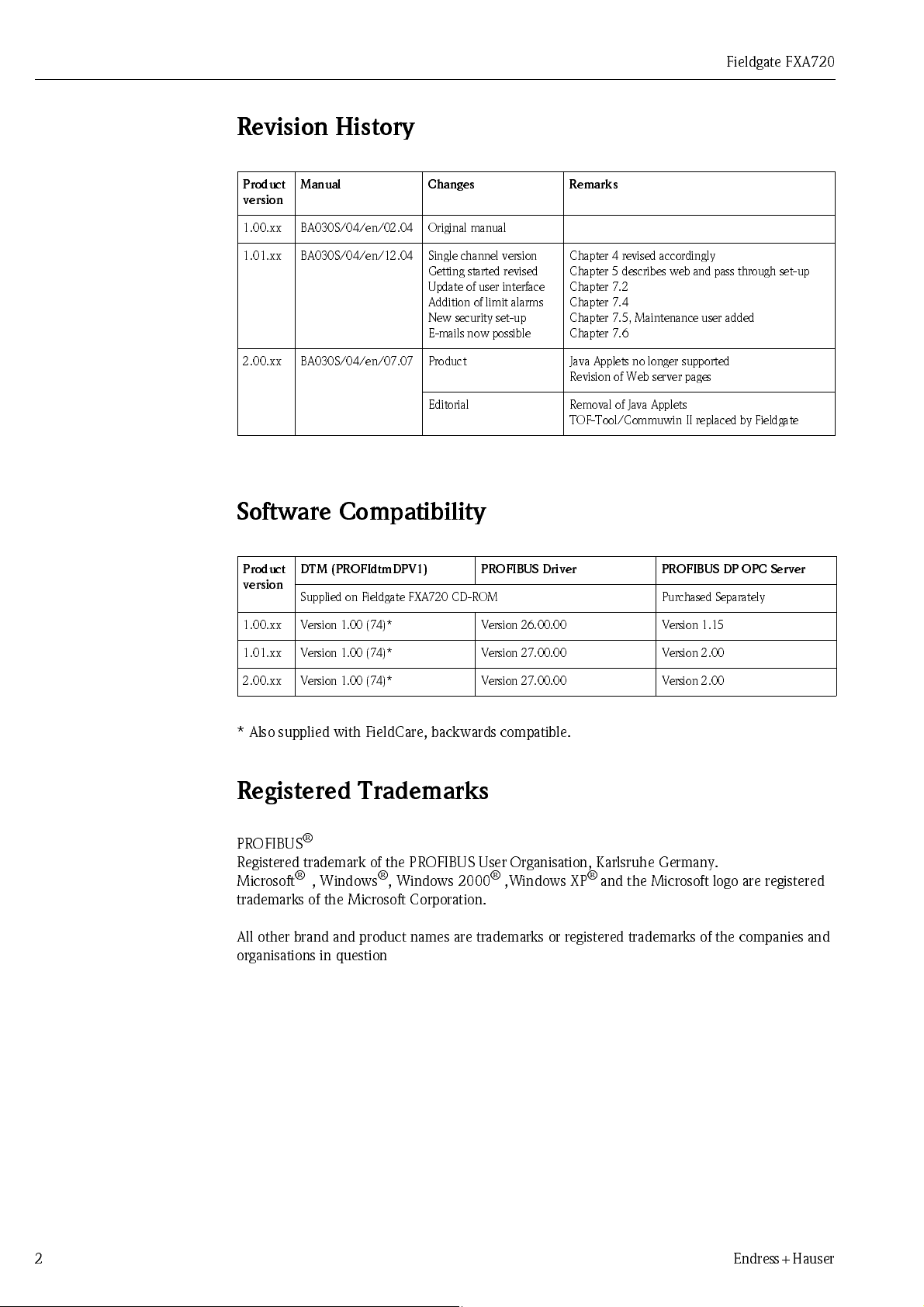
Revision Hi story
Fieldgate FXA720
Product
version
1.00.xx BA030S/04/en/02.04 Original manual
1.01.xx BA030S/04/en/12.04 Single channel version
2.00.xx BA030S/04/en/07.07 Product Java Applets no longer supported
Manual Changes Remarks
Chapter 4 revised accordingly
Getting started revised
Update of user interface
Addition of limit alarms
New security set-up
E-mails now possible
Editorial Removal of Java Applets
Chapter 5 describes web and pass through set-up
Chapter 7.2
Chapter 7.4
Chapter 7.5, Maintenance user added
Chapter 7.6
Revision of Web server pages
TOF-Tool/Commuwin II replaced by Fieldgate
Software Compatibil ity
Product
version
1.00 . xx V ers i o n 1 .0 0 ( 74)* Versio n 26. 0 0.00 V e r sio n 1.15
DTM (PROFIdtmDPV1) PROFIBUS Driver PROFIBUS DP OPC Server
Supplied on Fieldgate FXA720 CD-ROM Purchased Separately
1.01 . xx V ers i o n 1 .0 0 ( 74)* Versio n 27. 0 0.00 V e r sio n 2. 00
2.00. xx V ers i o n 1 .0 0 ( 74)* Versio n 27. 0 0.00 V e r sio n 2. 00
* Also supplied with FieldCare, backwards compatible.
Registered Trademarks
PROFIBUS
Registered trademark of the PROFIBUS User Organisation, Karlsruhe Germany.
Microsoft
trademarks of the Microsoft Corporation.
All other brand and product names are trademarks or registered trademarks of the companies and
organisations in question
®
®
, Windows®, Windows 2000® ,Windows XP® and the Microsoft logo are registered
2 Endress+Hauser
Page 5
Fieldgate FXA720 1 Safety
1 Safety
1.1 Designated use
Fieldgate FXA720 is a PROFIBUS/Ethernet Gateway with integrated web server that can be used:
• as a PROFIBUS DP/Ethernet gateway within a PROFIBUS monitoring and control system
• as a remote data acquisition module for PROFIBUS devices connected to its PROFIBUS DP
channels.
More information on these applications is to be found in the manual, or visit the Fieldgate web page
at www.products.endress.com/fieldgate.
1.2 Installation, commissioning and operation
Fieldgate FXA720 must be installed, connected, operated and maintained according to the
instructions in this manual: personnel must be authorised and suitably qualified.
Warning
• You require a unique IP address to set up Fieldgate. The use of IP addresses is strictly
controlled. Usually your system administrator will be authorised to allocate unique addresses
for your Fieldgates. Assigning an unauthorised address to a Fieldgate may result in conflicts
within your system and the failure of the associated devices!
Repair
1.3 Operational safety
The uni t m us t no t b e use d i n e x p l o si o n haz ar d ous areas. T he p e r mi s si b l e am b i en t co nd i t i o ns gi v e n
in the technical data must be complied with.
Do not open the housing of the Fieldgate FXA720. It does not contain any parts that need to be
maintained or repaired by the user. In the event of a fault or defect, return the unit to the vendor.
Opening the unit will void the warranty!
1.4 Technical improvement
Endr ess+ Haus er r ese rv es th e r ight to mak e te chni cal i mp ro vem ents to its har dwar e an d so ft war e at
any time and without prior notification. Where such improvements have no effect on the operation
of the equipment, they are not documented. If the improvements effect operation, a new version of
the operating instructions is normally issued, see Revision History.
Endress+Hauser 3
Page 6
1Safety Fieldgate FXA720
1.5 Declaration of conformity
CE Notice
North America
Fieldgate FXA720 complies with the requirements of the EC Directives 89/336/EEC
"Electromagnetic Compatibility" (EMC directive).
• Emission: EN 50022:1998 Class A (ITE Product Standard)
EN 50011:1998 Group 1 Class A (ISM Product Standard)
• Immunity: EN 61000-4-5:1999 Generic Immunity Standard
EN 61000-4-3: 1996 RF Electromagnetic Fields
A Declaration of Conformity in compliance with the above standards has been made and can be
inspected at Endress+Hauser Process Solutions AG on request.
Fieldgate FXA720 conforms with the following North American Electromagnetic Compatibility
standards:
• UL 508: Industrial Control Equipment
• CSA C22.2 # 14.795: Industrial Control Equipment
Note!
• For compliance with the legal EMC requirements, the other components (AC adapter, PROFIBUS
stations, etc.) must also meet these requirements.
• To meet t he EM C co nd iti on s, the de vice must be i nst all ed and conne cted i n acco rd ance w ith the
Installation Instructions.
Warning!
• This is a Class A product. In a domestic environment this product may cause radio interference
in which case the user may be required to take adequate measures.
FCC
This equipment has been tested and found to comply with the limits for a Class A digital device,
pursuant to part 15 of the FCC Rules. These limits are designed to provide reasonable protection
against harmful interference when the equipment is operated in a commercial environment. This
equi p m en t ge ne r at es, us es, and can r adiat e radi o f reque ncy e ne rgy and , i f not i ns ta l l ed and use d i n
accordance with the instruction manual, may cause harmful interference to radio communications.
Operation of this equipment in a residential area is likely to cause harmful interference in which
case the user will be required to correct the interference at his own expense.
4 Endress+Hauser
Page 7
Fieldgate FXA720 1 Safety
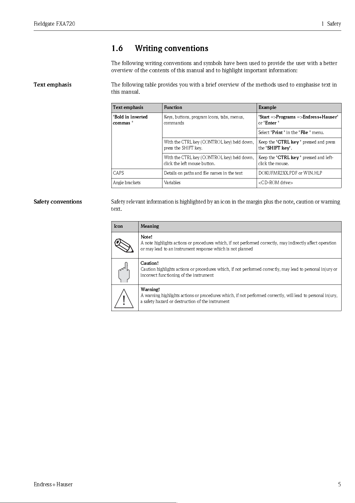
1.6 Writing conventions
The following writing conventions and symbols have been used to provide the user with a better
overview of the contents of this manual and to highlight important information:
Text emphasis
Safety conventions
The following table provides you with a brief overview of the methods used to emphasise text in
this manual.
Text emphasis Function Example
"
Bold in inverted
commas
CAPS Details on paths and file names in the text DOKUFMR2XX.PDF or WIN.HLP
Angle brackets Variables <CD-ROM drive>
"
Keys, buttons, program icons, tabs, menus,
commands
With the CTRL key (CONTROL key) held down,
press the SHIFT key.
With the CTRL key (CONTROL key) held down,
click the left mouse button.
"
Start
=>
Programs
or "
Enter
"
Select "
Print
" in the "
Keep the "
the "
Keep the "
click the mouse.
CTRL key
SHIFT key
CTRL key
=>
Endress+Hauser
File
" menu.
" pressed and press
".
" pressed and left-
Safety relevant information is highlighted by an icon in the margin plus the note, caution or warning
text .
.
Icon Meaning
Note!
A note highlights actions or procedures which, if not performed correctly, may indirectly affect operation
or may lead to an instrument response which is not planned
"
Caution!
Caution highlights actions or procedures which, if not performed correctly, may lead to personal injury or
incorrect functioning of the instrument
Warning!
A warning highlights actions or procedures which, if not performed correctly, will lead to personal injury,
a safety hazard or destruction of the instrument
Endress+Hauser 5
Page 8
1Safety Fieldgate FXA720
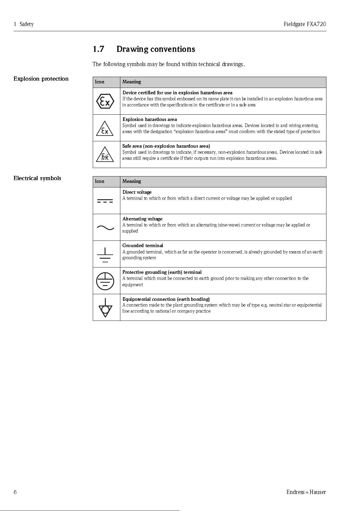
1.7 Drawing conventions
The following symbols may be found within technical drawings.
Explos i on prot ect ion
Elect ric al s ymbol s
.
Icon Meaning
Device certified for use in explosion hazardous area
If the device has this symbol embossed on its name plate it can be installed in an explosion hazardous area
in accordance with the specifications in the certificate or in a safe area
Explosion hazardous area
Symbol used in drawings to indicate explosion hazardous areas. Devices located in and wiring entering
areas with the designation “explosion hazardous areas” must conform with the stated type of protection
Safe area (non-explosion hazardous area)
Symbol used in drawings to indicate, if necessary, non-explosion hazardous areas. Devices located in safe
areas stiill require a certificate if their outputs run into explosion hazardous areas.
.
Icon Meaning
Direct voltage
A terminal to which or from which a direct current or voltage may be applied or supplied
Alternating voltage
A terminal to which or from which an alternating (sine-wave) current or voltage may be applied or
supplied
Grounded terminal
A grounded terminal, which as far as the operator is concerned, is already grounded by means of an earth
grounding system
Protective grounding (earth) terminal
A terminal which must be connected to earth ground prior to making any other connection to the
equipment
Equipotential connection (earth bonding)
A connection made to the plant grounding system which may be of type e.g. neutral star or equipotential
line according to national or company practice
6 Endress+Hauser
Page 9
Fieldgate FXA720 2 Identification
2 Identification
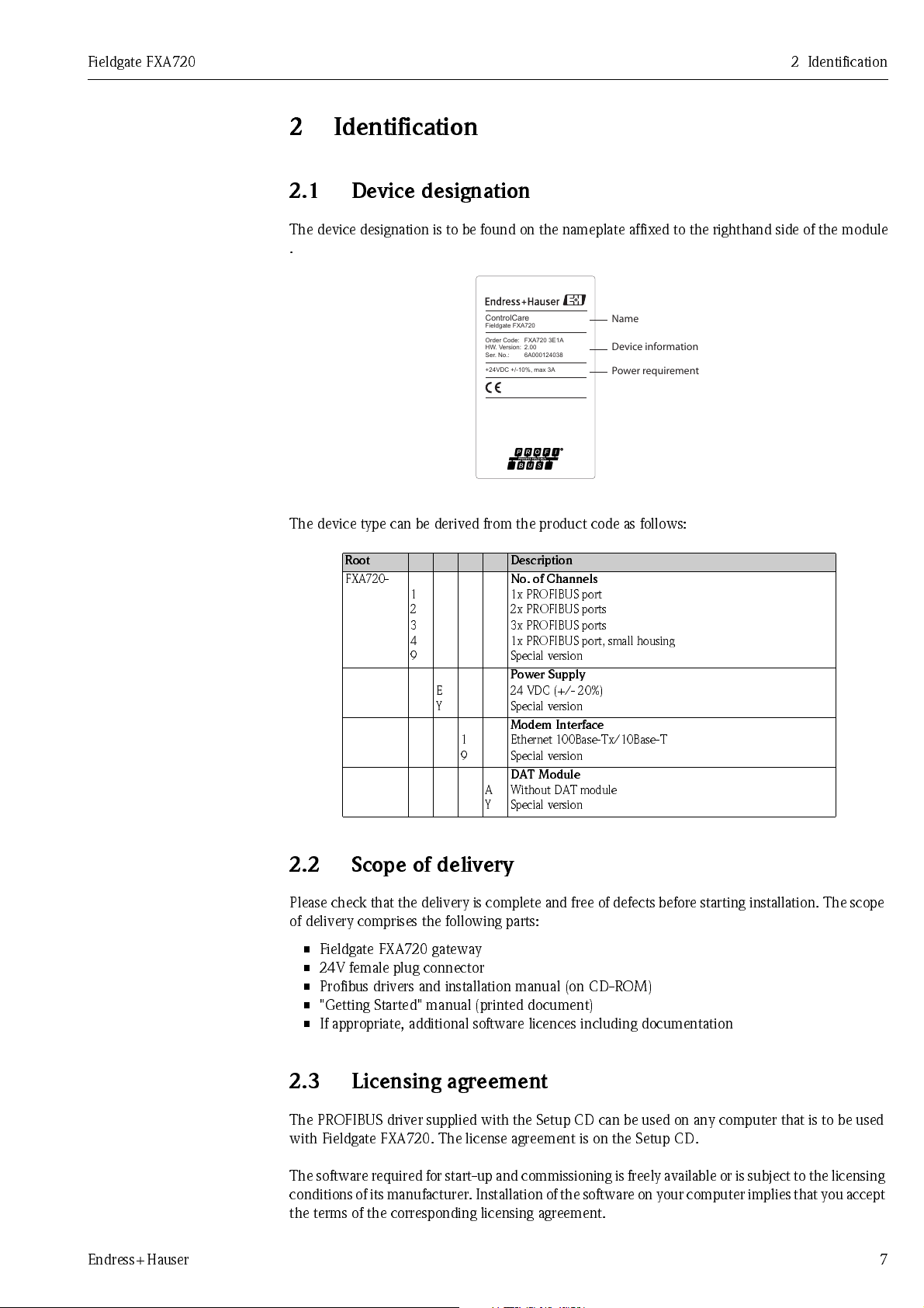
2.1 Device designation
The device designation is to be found on the nameplate affixed to the righthand side of the module
.
ControlCare
Fieldgate FXA720
FXA720 3E1A
Order Code:
2.00
HW. Version:
6A000124038
Ser. No.:
+24VDC +/-10%, max 3A
Name
Device information
Power requirement
The device type can be derived from the product code as follows:
Root Description
FXA720-
1
2
3
4
9
E
Y
1
9
No. of Channels
1x PROFIBUS port
2x PROFIBUS ports
3x PROFIBUS ports
1x PROFIBUS port, small housing
Special version
Power Supply
24 VDC (+/- 20%)
Special version
Modem Interface
Ethernet 100Base-Tx/10Base-T
Special version
DAT Module
A
Without DAT module
Y
Special version
2.2 Scope of delivery
Please check that the delivery is complete and free of defects before starting installation. The scope
of delivery comprises the following parts:
• Fieldgate FXA720 gateway
• 24V female plug connector
• Profibus drivers and installation manual (on CD-ROM)
• "Getting Started" manual (printed document)
• If appropriate, additional software licences including documentation
2.3 Licensing agreement
The PROFIBUS driver supplied with the Setup CD can be used on any computer that is to be used
with Fieldgate FXA720. The license agreement is on the Setup CD.
The software required for start-up and commissioning is freely available or is subject to the licensing
condi tio ns of its m anufact urer . Ins talla tion of t he sof tware on you r com puter imp lies that you acce pt
the terms of the corresponding licensing agreement.
Endress+Hauser 7
Page 10
3 Function and System Design Fieldgate FXA720
3 Function and Sys tem De si gn
3.1 Function
Fieldgate FXA720 connects host systems to PROFIBUS DP networks via Ethernet. It can be
equipped with up to three RS-485 ports, each giving access to up to 125 PROFIBUS DP devices.
Fieldgate is designed for Windows and web-based applications such as configuration, monitoring,
and visualisation. Process data can be monitored with the integrated Web server.
Fieldgate can also be integrated into system applications via OPC, DTM or XML, eg.:
• OPC for exchanging data with applications such as SCADA/HMI OPC clients,
e.g. P View SPV200
• DTM for exchanging data with FDT frame applications, e.g. FieldCare
• XML for exchanging data with Microsoft Office applications or simple visualisation applications
such as Field Viewer SPV10
8 Endress+Hauser
Page 11
Fieldgate FXA720 3 Function and System Design
3.2 Design
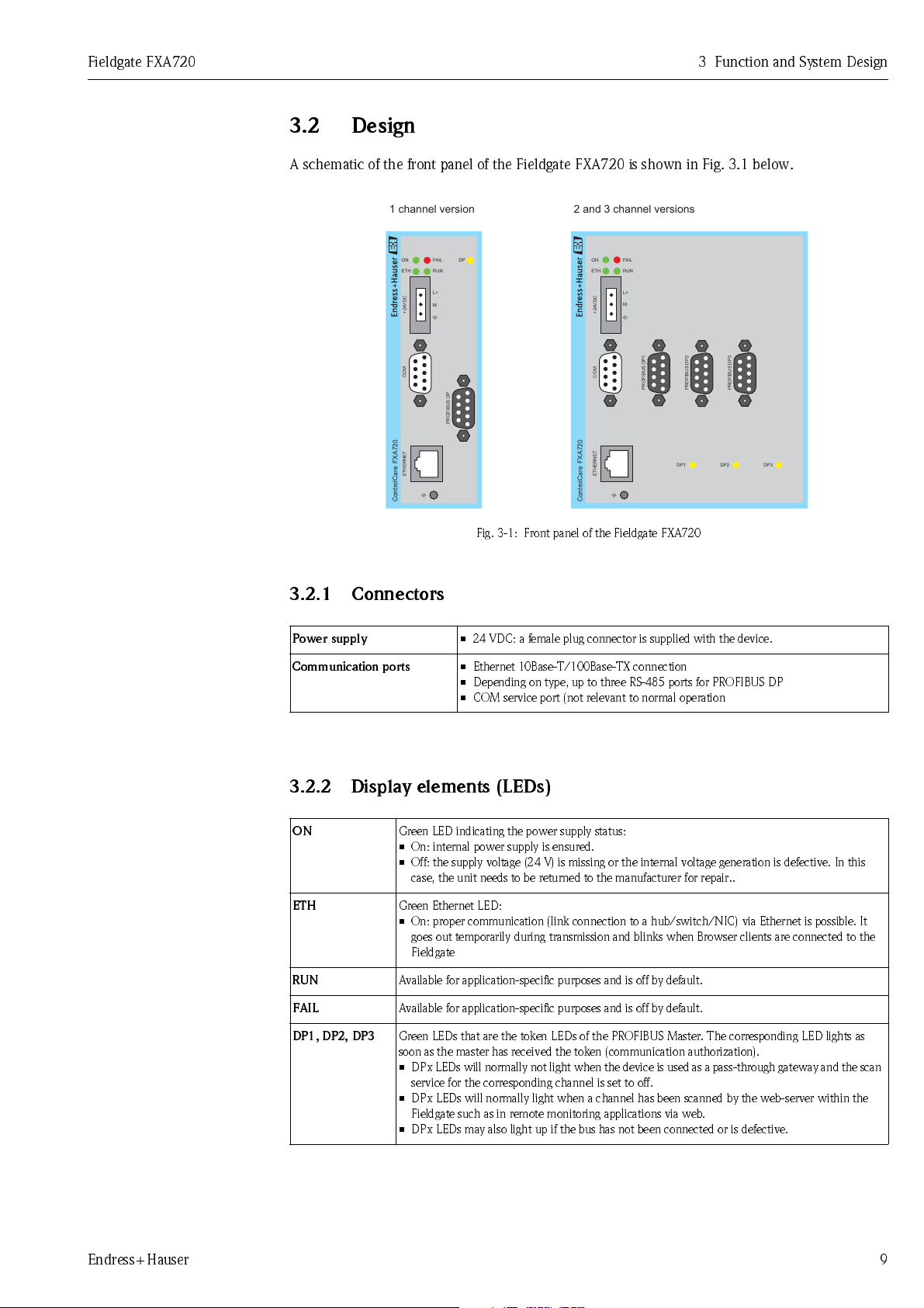
A schematic of the front panel of the Fieldgate FXA720 is shown in Fig. 3.1 below.
1 channel version 2 and 3 channel versions
FAIL
ON
ETH
+24VDC
FAIL
DP
RUN
L+
M
ON
ETH
+24VDC
RUN
L+
M
COM
PROFIBUS DP
FXA720ControlCare
ETHERNET
Fig. 3-1: Front panel of the Fieldgate FXA720
3.2.1 Connectors
Power supply
Communication ports
• 24 VDC: a female plug connector is supplied with the device.
• Ethernet 10Base-T/100Base-TX connection
• Depending on type, up to three RS-485 ports for PROFIBUS DP
• COM service port (not relevant to normal operation
3.2.2 Display elements (LEDs)
COM
FXA720ControlCare
ETHERNET
PROFIBUS DP1
DP1
PROFIBUS DP2
PROFIBUS DP3
DP2 DP3
ON
Green LED indicating the power supply status:
• On: internal power supply is ensured.
• Off: the supply voltage (24 V) is missing or the internal voltage generation is defective. In this
case, the unit needs to be returned to the manufacturer for repair..
ETH
Green Ethernet LED:
• On: proper communication (link connection to a hub/switch/NIC) via Ethernet is possible. It
goes out temporarily during transmission and blinks when Browser clients are connected to the
Fieldgate
RUN
FAIL
DP1, DP2, DP3
Available for application-specific purposes and is off by default.
Available for application-specific purposes and is off by default.
Green LEDs that are the token LEDs of the PROFIBUS Master. The corresponding LED lights as
soon as the master has received the token (communication authorization).
• DPx LE Ds will normally not lig ht when the device is used as a pass-through gateway and the scan
service for the corresponding channel is set to off.
• DPx LEDs will normally light when a channel has been scanned by the web-server within the
Fieldgate such as in remote monitoring applications via web.
• DPx LEDs may also light up if the bus has not been connected or is defective.
Endress+Hauser 9
Page 12
3 Function and System Design Fieldgate FXA720
3.3 System architecture
Web-base d appl icat io ns
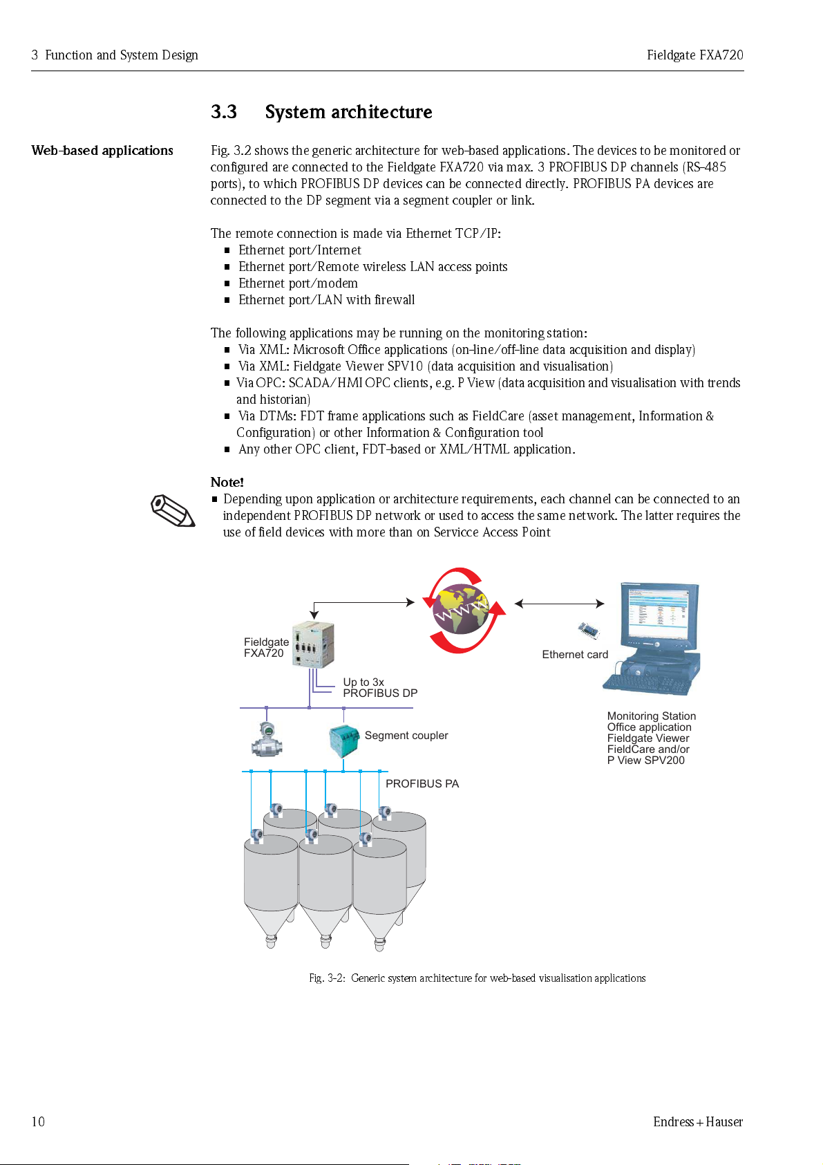
Fig. 3.2 shows the generic architecture for web-based applications. The devices to be monitored or
configured are connected to the Fieldgate FXA720 via max. 3 PROFIBUS DP channels (RS-485
ports), to which PROFIBUS DP devices can be connected directly. PROFIBUS PA devices are
connected to the DP segment via a segment coupler or link.
The remote connection is made via Ethernet TCP/IP:
• Ethernet port/Internet
• Ethernet port/Remote wireless LAN access points
• Ethernet port/modem
• Ethernet port/LAN with firewall
The following applications may be running on the monitoring station:
• Via XML: Microsoft Office applications (on-line/off-line data acquisition and display)
• Via XML: Fieldgate Viewer SPV10 (data acquisition and visualisation)
• Via OPC: SCADA/HMI OPC clients, e.g. P View (data acquisition and visualisation with trends
and historian)
• Via DTMs: FDT frame applications such as FieldCare (asset management, Information &
Configuration) or other Information & Configuration tool
• Any other OPC client, FDT-based or XML/HTML application.
Note!
• Dependi ng up o n ap p l i cat i o n o r ar ch i te ct ur e r eq u i rements , each chan nel can be co nnected to an
independent PROFIBUS DP network or used to access the same network. The latter requires the
use of field devices with more than on Servicce Access Point
Fieldgate
FXA720
Ethernet card
Up to 3x
PROFIBUS DP
Monitoring Station
Segment coupler
PROFIBUS PA
Fig. 3-2: Generic system architecture for web-based visualisation applications
Office application
Fieldgate Viewer
FieldCare and/or
P View SPV200
10 Endress+Hauser
Page 13
Fieldgate FXA720 3 Function and System Design
Fieldgate
FXA720
PROFIBUS DP
Segment
coupler
Segment
coupler
PROFIBUS PAPROFIBUS PA
ETHERNET
HMI
e.g. P View
Asset Management
e.g. FieldCare
Enterprise
e.g. Office
Controller
e.g.
ControlCare
SFC173
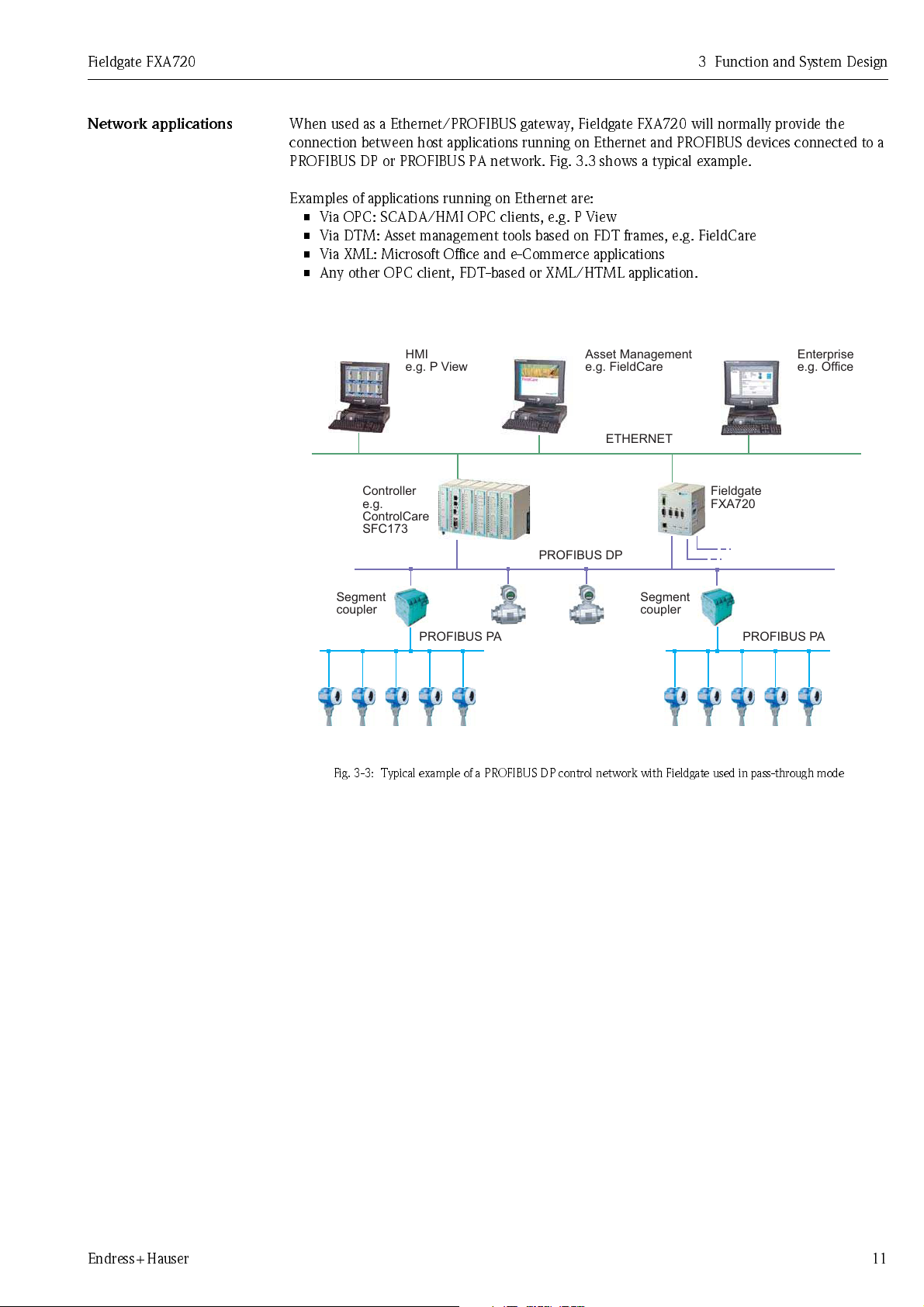
Network applications
When used as a Ethernet/PROFIBUS gateway, Fieldgate FXA720 will normally provide the
connection between host applications running on Ethernet and PROFIBUS devices connected to a
PROFIBUS DP or PROFIBUS PA network. Fig. 3.3 shows a typical example.
Examples of applications running on Ethernet are:
• Via OPC: SCADA/HMI OPC clients, e.g. P View
• Via DTM: Asset management tools based on FDT frames, e.g. FieldCare
• Via XML: Microsoft Office and e-Commerce applications
• Any other OPC client, FDT-based or XML/HTML application.
Fig. 3-3: Typical example of a PROFIBUS DP control network with Fieldgate used in pass-through mode
Endress+Hauser 11
Page 14
3 Function and System Design Fieldgate FXA720
3.4 System requirements
Operating Syste m
Remot e monit oring via w eb
browser
Remote Information &
Configuration with
PROFIBUS Clie nt
SCADA and vis uali s atio n
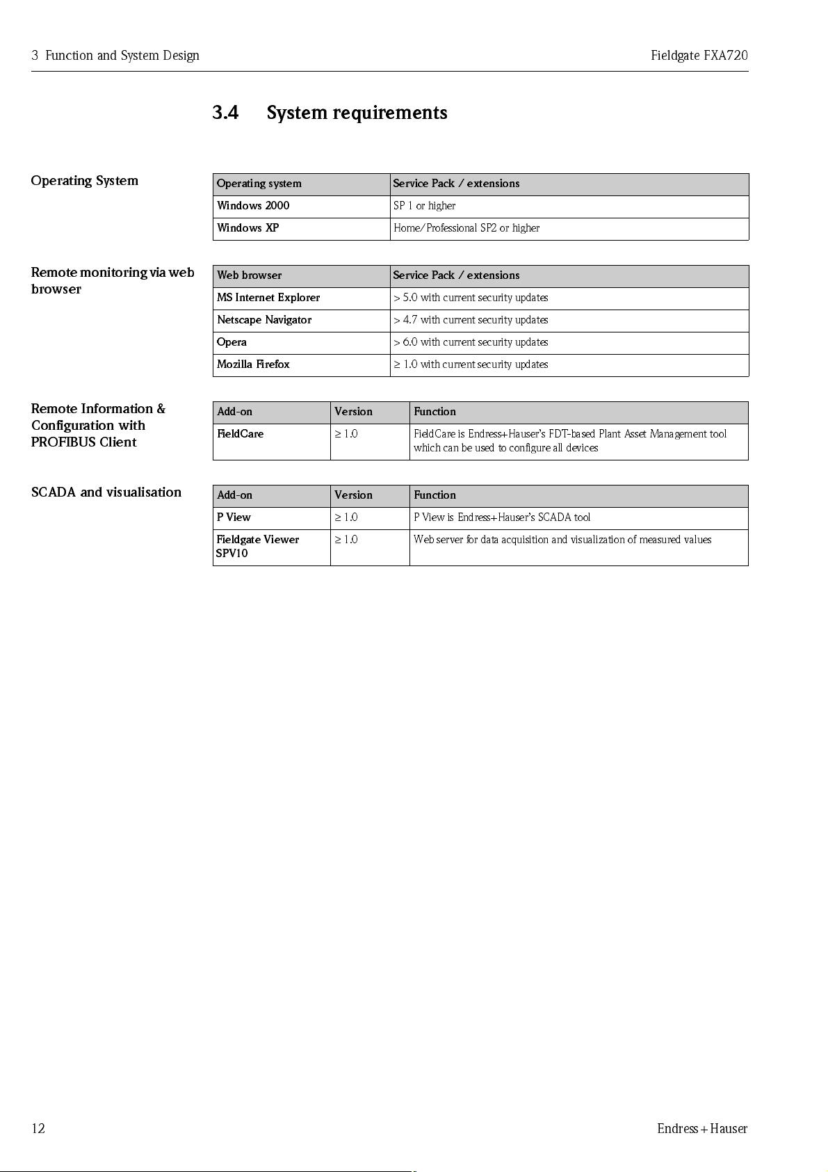
Operating system Service Pack / extensions
Windows 2000
Windows XP
Web browser Service Pack / extensions
MS Internet Explorer
Netscape Navigator
Opera
Mozilla Firefox
Add-on Version Function
FieldCare
Add-on Version Function
P View
Fieldgate Viewer
SPV10
≥
1.0 FieldCare is Endress+Hauser’s FDT-based Plant Asset Management tool
≥
1.0 P View is Endress+Hauser’s SCADA tool
≥
1.0 Web server for data acquisition and visualization of measured values
SP 1 or higher
Home/Professional SP2 or higher
> 5.0 with current security updates
> 4.7 with current security updates
> 6.0 with current security updates
≥
1.0 with current security updates
which can be used to configure all devices
12 Endress+Hauser
Page 15
Fieldgate FXA720 4 Hardware Installation
111 m m
35 mm
top hat rail
135 mm
30 mm
clearance
30 mm
clearance
FAIL
ON
ETH
RUN
+24VDC
COM
PROFIBUS DP1
ETHERNET
DP1
PROFIBUS DP2
PROFIBUS DP3
DP2 DP3
L+
M
FXA720ControlCare
COM
ETHERNET
PROFIBUS DP
FAIL
ON
ETH
RUN
DP
+24VDC
L+
M
FXA720ControlCare
46.5 mm
4 Hardware Ins tall ation
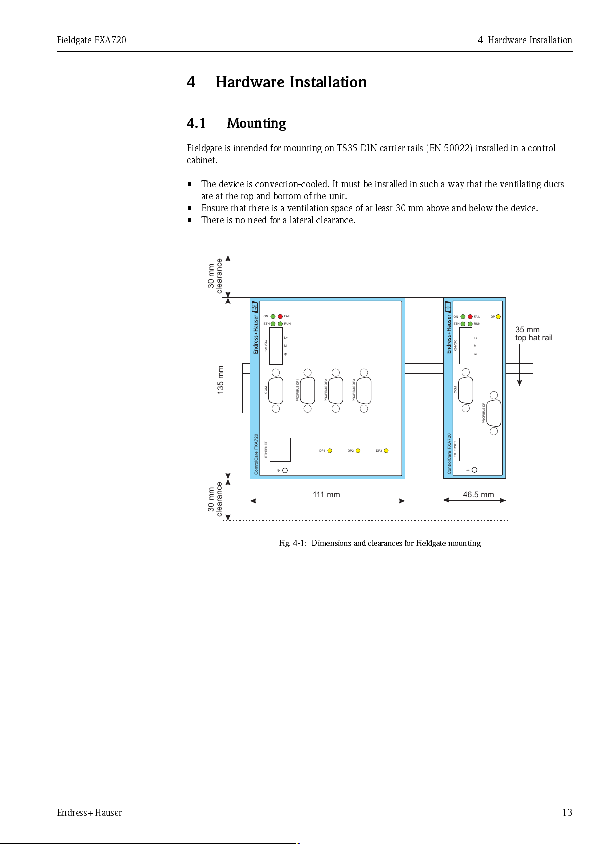
4.1 Mounting
Fieldgate is intended for mounting on TS35 DIN carrier rails (EN 50022) installed in a control
cabinet.
• The device is convection-cooled. It must be installed in such a way that the ventilating ducts
are at the top and bottom of the unit.
• Ensure that there is a ventilation space of at least 30 mm above and below the device.
• There is no need for a lateral clearance.
Fig. 4-1: Dimensions and clearances for Fieldgate mounting
Endress+Hauser 13
Page 16
4 Hardware In stall at i o n Fieldgate FXA720
4.2 Wiring
4.2.1 Power supply
Fieldgate FXA720 is powered by 24 V DC. The power supply female plug connector is included in
the delivery. The power supply male socket connector on the front panel is labeled 24VDC
(see Fig. 4.1).
The two power supply terminals are labeled L+ and L–.
• Connect L+ to +24 VDC and connect L– to 0 VDC.
The two terminals are provided with an internal reverse-polarity protection.
Grounding
Fuse
Proper grounding is prerequisite for compliance with the EMC directives and for ensuring a proper
operation.
• The functional ground terminal is labeled and must be connected to the protective ground.
• F o r us e i n a n e nv i r o nm en t th at i s hi gh l y sub j e ct to el e ct r o ma gn et i c i n te r f e r en ce, an ad d i t i o na l
ground connection can be provided at the grounding screw below the "ETH" connector.
The p ower sup pl y is co nnect ed to the plu g conn ecto r v ia f lex ib le wir es wit h a cro ss -se cti on o f 0. 75
to 1.5 mm². The ground connection wire must have a cross-section of 1.5 mm².
The Fi eld gate FX A720 has an i nter nal safe ty fuse which bl ows if an over volt age occur s in the power
supply (of approx. 30V or higher) or if a fault occurs in the device. The safety fuse can be replaced
by the device manufacturer only.
Note!
• The start-up current of the Fieldgate FXA720 may be up to 3A. The power supply must provide
this starting current in compliance with the voltage range to ensure a safe startup.
14 Endress+Hauser
Page 17
Fieldgate FXA720 4 Hardware Installation
4.2.2 Communication ports
Ethernet
COM
PROFIBUS
The Ethernet port is labeled "ETH" and has been implemented as a 10Mbit/s or
100 Mbit/s (10Base-T/100Base-TX) connection with automatic baudrate recognition. The
connection is made using a RJ45 connector and a twisted pair category 5 cable.
• Use a crossover cable if Fieldgate is to be connected directly to a Ethernet NIC card in the
personal computer
• Use a straight through cable if the connection is to be made via a hub or switch
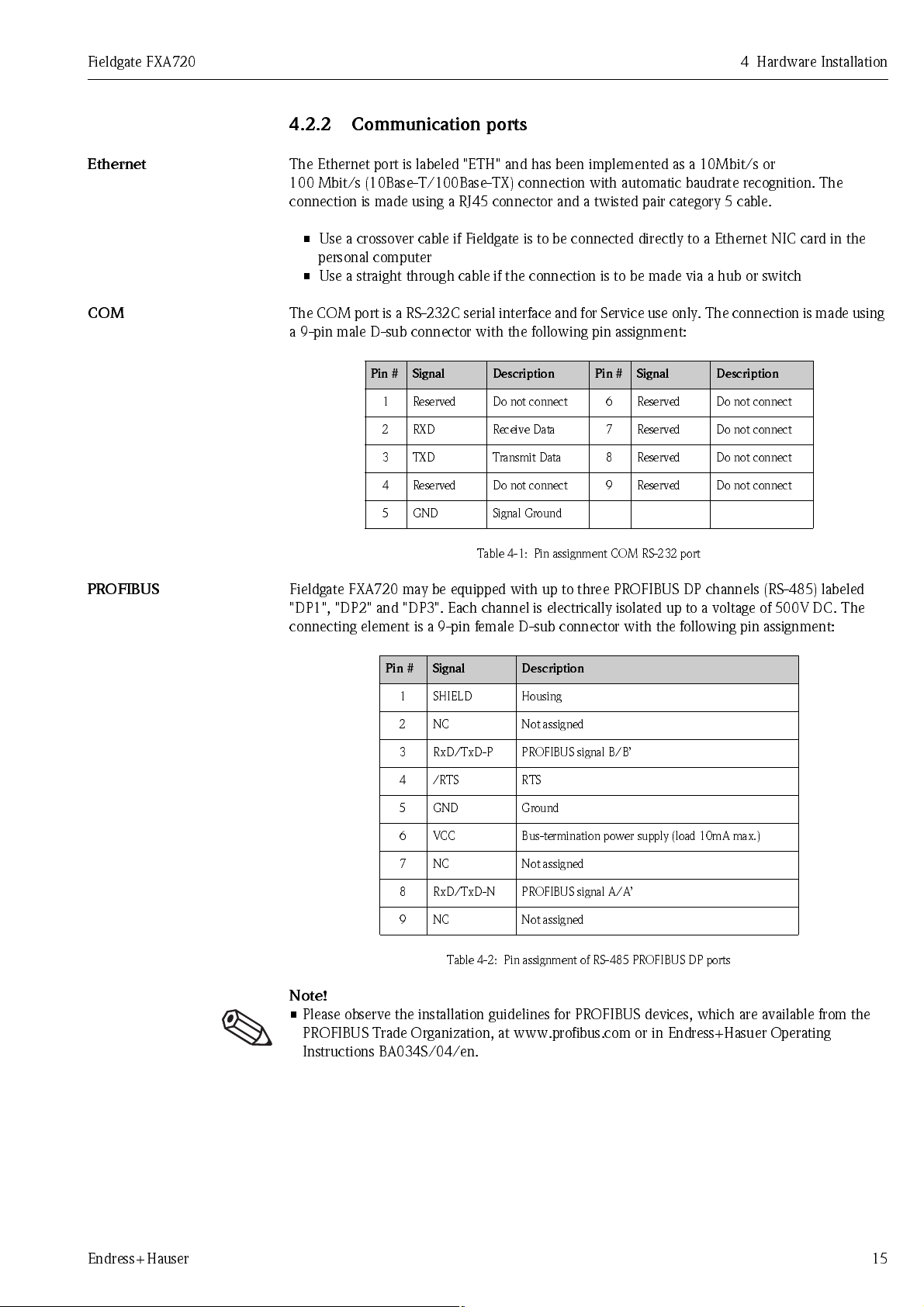
The COM port is a RS-232C serial interface and for Service use only. The connection is made using
a 9-pin male D-sub connector with the following pin assignment:
Pin # Signal Description Pin # Signal Description
1 Reserved Do not connect 6 Reserved Do not connect
2 RXD Receive Data 7 Reserved Do not connect
3 TXD Transmit Data 8 Reserved Do not connect
4 Reserved Do not connect 9 Reserved Do not connect
5 GND Signal Ground
Table 4-1: Pin assignment COM RS-232 port
Fieldgate FXA720 may be equipped with up to three PROFIBUS DP channels (RS-485) labeled
"DP1", "DP2" and "DP3". Each channel is electrically isolated up to a voltage of 500V DC. The
connecting element is a 9-pin female D-sub connector with the following pin assignment:
Pin # Signal Description
1SHIELD Housing
2 NC Not assigned
3 RxD/TxD-P PROFIBUS signal B/B’
4/RTS RTS
5 GND Ground
6 VCC Bus-termination power supply (load 10mA max.)
7 NC Not assigned
8 RxD/TxD-N PROFIBUS signal A/A’
9 NC Not assigned
Table 4-2: Pin assignment of RS-485 PROFIBUS DP ports
Note!
• Please observe the installation guidelines for PROFIBUS devices, which are available from the
PROFIBUS Trade Organization, at www.profibus.com or in Endress+Hasuer Operating
Instr u ct i o ns BA 03 4 S /04/en.
Endress+Hauser 15
Page 18
5 Getting Started Fieldgate FXA720
5 Getting Started
Before you start the installation:
• Check that you have administrator rights for your computer.
• Check that you have a unique IP address for each Fieldgate to be installed together with
subnet, gateway (LAN/router/firewall) and, if appropriate, broadcast IP addresses.
If a previous version is installed on your computer, we recommend that you deinstall it before
installing the new version.
Warning!
• The use of IP addresses is strictly controlled. Usually your system administrator will be
authorised to allocate unique addresses for your Fieldgates. Assigning an unauthorised address
to a Fieldgate may result in conflicts within your system and the failure of the associated
devices!
5.1 Preparing for installation
Procedure
5.1.1 Checking the system requirements
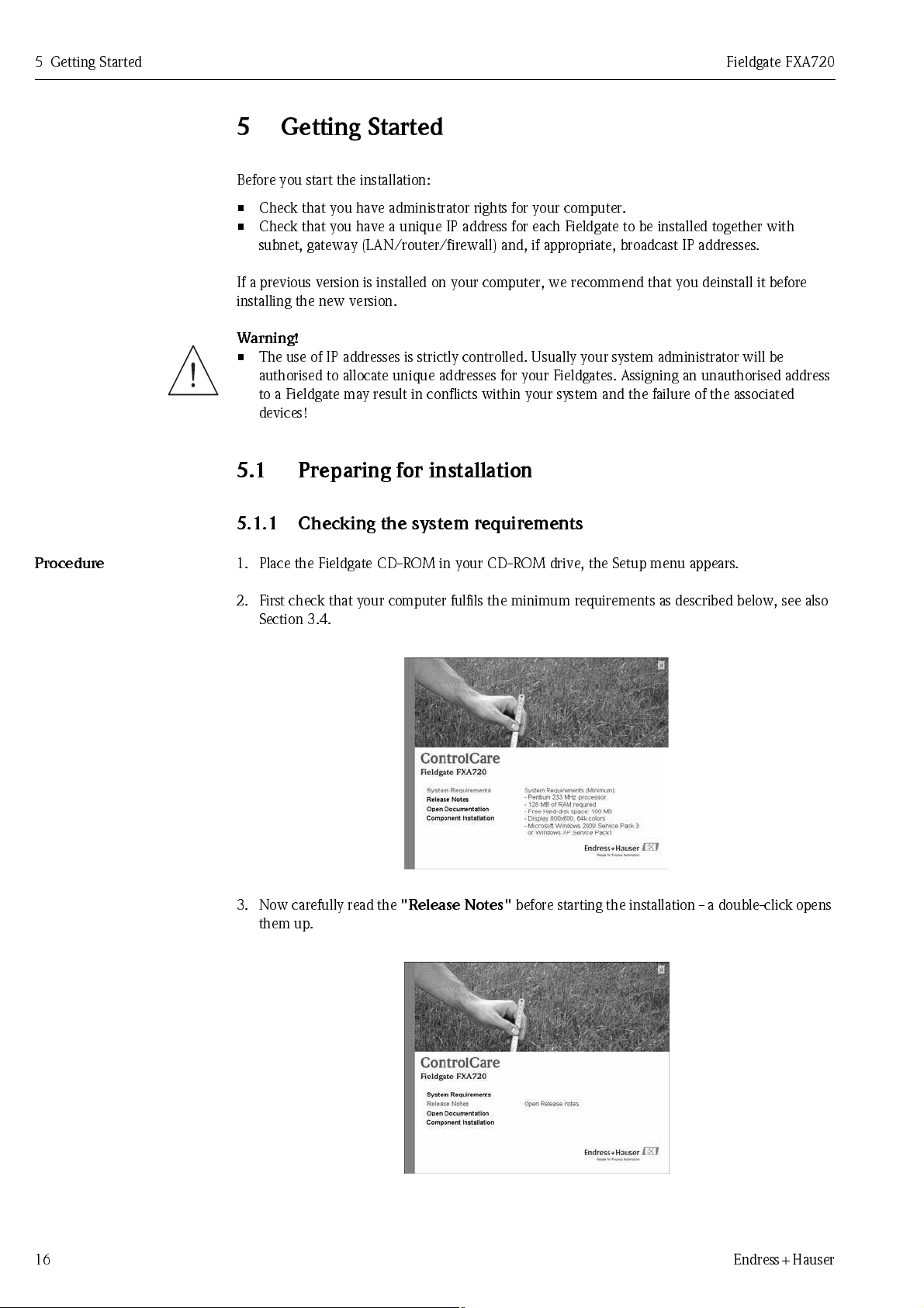
1. Place the Fieldgate CD-ROM in your CD-ROM drive, the Setup menu appears.
2. First check that your computer fulfils the minimum requirements as described below, see also
Section 3.4.
3. N ow car ef ull y re ad th e
them up.
"Release Notes"
before starting the installation - a double-click opens
16 Endress+Hauser
Page 19
Fieldgate FXA720 5 Getting Started
5.1.2 Installing the documentation
Procedure
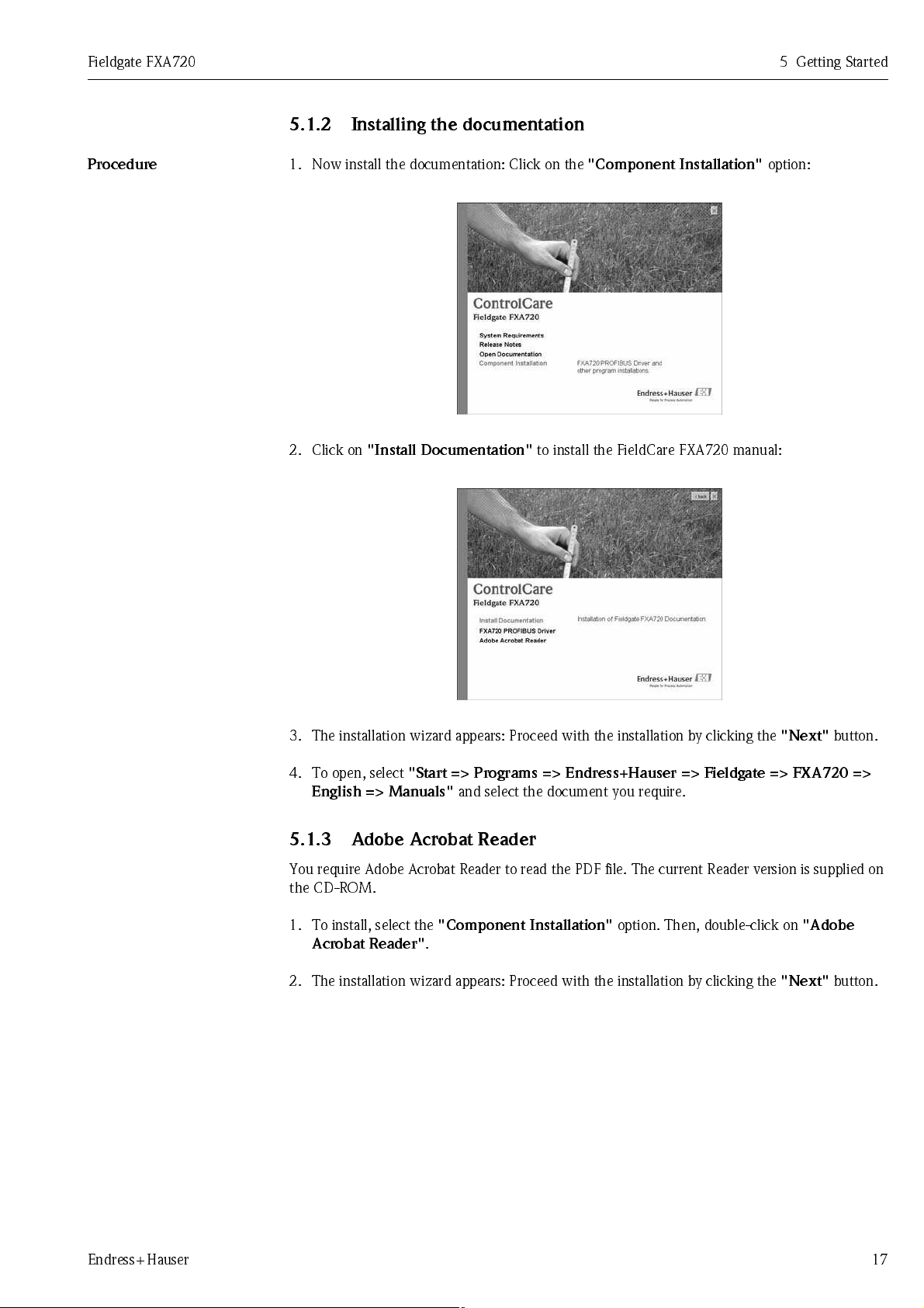
1. Now install the documentation: Click on the
2. Click on
"Install Doc ume ntati on"
to install the FieldCare FXA720 manual:
"Compone nt Instal lat io n"
option:
3. The installation wizard appears: Proceed with the installation by clicking the
4. To open, select
English => Manuals"
"Start => Programs => Endre ss +H aus er => Fieldgate => FXA 720 =>
and select the document you require.
"Next"
button.
5.1.3 Adobe Acrobat Reader
You require Adobe Acrobat Reader to read the PDF file. The current Reader version is supplied on
the CD-ROM.
1. To install, select the
Acrobat Reader"
2. The installation wizard appears: Proceed with the installation by clicking the
"Compo nent Inst all ati on"
.
option. Then, double-click on
"Next"
"Adobe
button.
Endress+Hauser 17
Page 20
5 Getting Started Fieldgate FXA720
5.2 Establishing communication
5.2.1 Making initial contact
Note!
• To make initial contact with the Fieldgate FXA720, the IP address of your computer must be
temporarily changed to the same domain as the Fieldgate default address (192.168.253.1). If
you are unsure of how to do this, consult your system administrator.
• The following procedure applies to internet connection via Windows XP. The procedures for
Windows 2000 is described in Chapter 11.
Before starting, the Fieldgate FXA720 must either:
• be installed in the network connected to a switch/hub with a straight cable or
• be connected directly to the computer with a cross-link cable.
Procedure
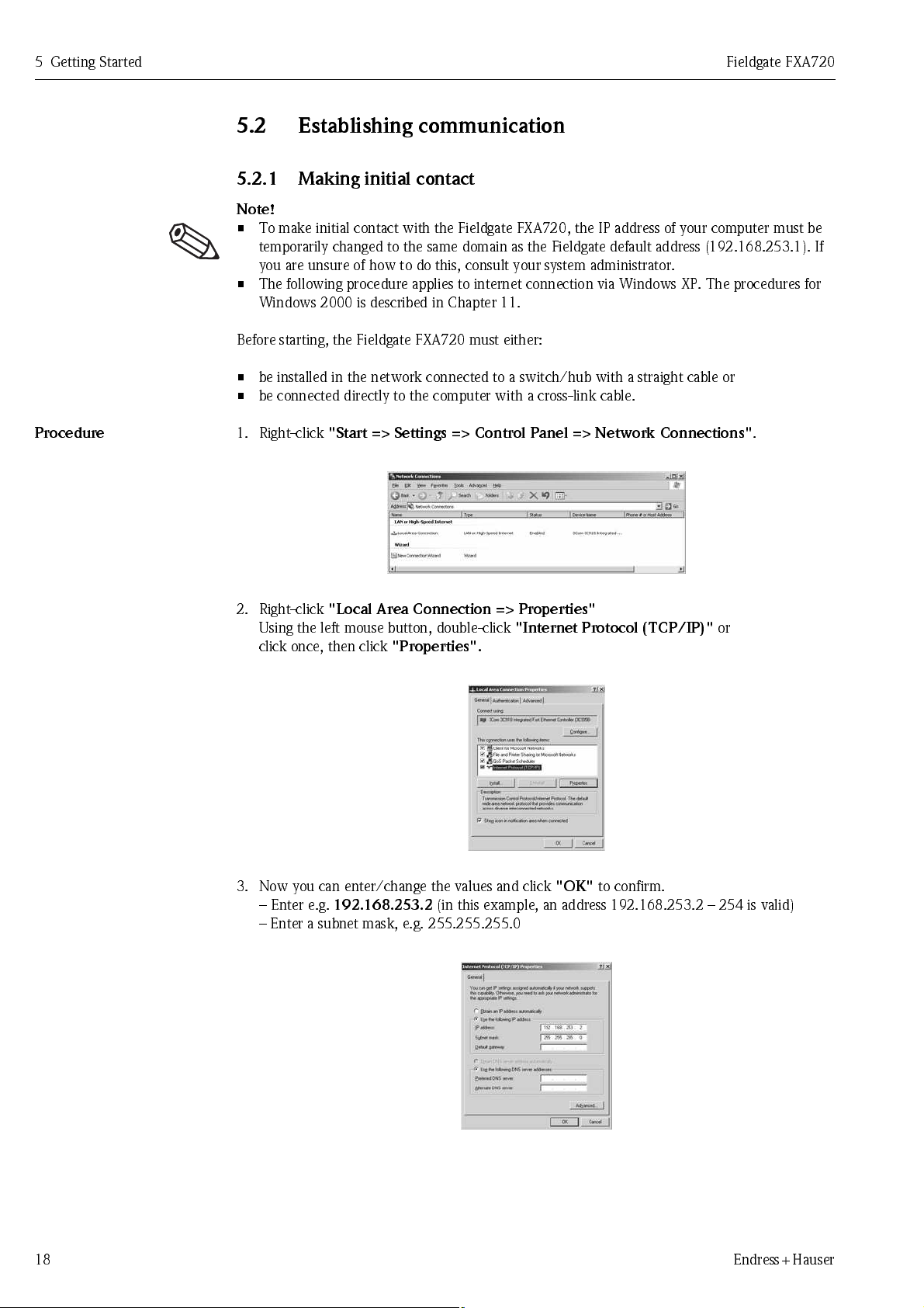
1. Right-click
2. Right-click
Using the left mouse button, double-click
click once, then click
"Start => Settings => Control Panel => Network Connections"
"Local Ar ea Co nnec tio n => Properti es"
"Properties".
"Internet Protocol (TCP/IP)"
.
or
3. Now you can enter/change the values and click
– Enter e.g.
– Enter a subnet mask, e.g. 255.255.255.0
18 Endress+Hauser
192.168.253.2
(in this example, an address 192.168.253.2 – 254 is valid)
"OK"
to confirm.
Page 21

Fieldgate FXA720 5 Getting Started
4. Start the web browser, e.g. Internet Explorer.
Now enter the default address of the Fieldgate
browser and press the
"Enter"
key of your computer.
"192.168.253.1"
in the address field of your
5. The br o wse r mak es conn ect i o n wi th the F i el d g at e, a User
– Enter the password:
– Press
– If no connection can be made, consult Chapter 12.3.
6. After the password has been entered, the Fieldgate Web Server opens
(you will not necessarily see devices at this point):
"Login"
"superb"
to display the entry page of the Fieldgate.
Login
window appears.
Endress+Hauser 19
Page 22

5 Getting Started Fieldgate FXA720
5.2.2 Changing the Fieldgate address
Procedure
1. Press "
2. The live list is displayed (you may not necessarily see devices at this stage)
3. Now press "
Switch to Specialist Mode
– Enter the user name "
– Press "
– All active addresses on the bus are displayed
– Masters are normally listed with N.A. entries
– In the
– Enter the
– If appropriate, enter a
Login
"
Information & Co nfigu rati on
Ethernet
in this example 192.168.253.50:
Subnet mask
admin"
screen enter the
, in this example 255.255.255.0
Gateway
"
and password "
" followed by "
IP address
address (router/firewall connecting LAN to WAN/WWW)
super
"
Network Setup
given to you by the system administrator,
"
– Press
4. Contact with the Fieldgate may break down at this stage.
In all cases, close the browser.
5. Reset the IP address in your computer back to the original value, see Section 5.2.1.
6. You can now make contact with Fieldgate FXA720 through the network browser by entering
the new address.
7. Now set up the Fieldgate web server as described in Chapter 6.
20 Endress+Hauser
"Send"
to download the parameters to the Fieldgate.
Page 23

Fieldgate FXA720 5 Getting Started
5.3 Installing FXA720 PROFIBUS Driver
The FXA720 PROFIBUS Driver must be installed only if Fieldgate FXA720 is to be used in pass-
through mode to allow a host application, e.g. P View, to access a PROFIBUS DP network.
Warning!
• Do not install this driver if a Fieldgate PROFIBUS driver has already been installed with the
Host application, e.g. in connection with FieldCare. Overwriting the original will cause the
application to malfunction. You will be warned during installation, if a driver already exists.
5.3.1 Installing the driver
Procedure
1. Place the Fieldgate CD-ROM in your CD-ROM drive, the Setup menu appears.
2. Click on
3. Click on
"Component Installation"
"FXA 720 PRO FIBUS Drive r"
to start the software installation process.
to install the Fieldgate tool.
4. The Setup program immediately starts the installation process.
Endress+Hauser 21
Page 24

5 Getting Started Fieldgate FXA720
5. Read the license agreement and check "
– "Print"
– "C a n c el "
6. Now enter your customer information
Press
causes the license to be printed out
breaks off the installation procedure
"Next"
to proceed.
I accept ...
" then press "
Next".
7. Press
8. Press
"Install"
"Finish"
to start the installation.
to close the wizard.
22 Endress+Hauser
Page 25

Fieldgate FXA720 5 Getting Started
5.3.2 Configuring the driver
Procedure
1. Open the Control Panel via
Double-click on the
Note!
If you are using Fieldgate FXA720 with FieldCare, the select the
2. Select the
3. Now select the
PROFIBUS DP
"Fieldgate FXA720"
START => Settings => Control Panel .
"Fieldgate FXA720"
line, to display the general release information
icon to open the driver.
line and press
"Add"
"PROFIGate"
.
driver
4. A symbolic node name for each PROFIBUS DP channel (Default value: "Node 0") can now be
entered. Click
Endress+Hauser 23
"Next"
to proceed with the configuration.
Page 26

5 Getting Started Fieldgate FXA720
5. Enter the current
with the node specified in Step 4).
6. Click "
Finish
Caution:
Timeout settings should be changed by PROFIBUS specialists only
Fieldgate IP
" to accept the default timeout settings and end the configuration.
address and select the
Bus connector
(the channel to be used
7. If the Fieldgate is found in the network and is working properly, then the Node line will be
marked with a green check mark. In addition, Fieldgate information is displayed.
– The node configuration can be modified from this screen by clicking the
"Edit"
button. To save the configuration please click
8. For single channel Fieldgates, press
configuration window, otherwise continue with Step 9.
"OK"
to store the configuration and close the
"Apply".
24 Endress+Hauser
Page 27

Fieldgate FXA720 5 Getting Started
For two and three channel
versio ns
9. Now configure the other channels of your Fieldgate by pressing the
– Follow the sequence from Step 3 to Step 5 inclusive.
– Enter the same IP address: Fieldgate requires only one IP address for operation.
– Select
10.Click "
Caution:
"Bus 2" or "Bus 3"
Finish
" to accept the default timeout settings and end the configuration.
Timeout settings should be changed by PROFIBUS specialists only
as appropriate.
"Add".
button.
11.On completion, the new node will be added to the network tree:
– Press
Note: the screenshot shows the two channel version.
12.When all channels have been configured, press
configuration window.
"Apply"
to store the configuration
"OK"
to store the configuration and close the
Endress+Hauser 25
Page 28

5 Getting Started Fieldgate FXA720
5.3.3 Setting PROFIBUS DP bus parameters in FieldCare
Note!
• FieldCare uses the PROFIGate driver for Fieldgate FXA720. This should be configured before
the PROFIBUS DP parameters are set (The procedure is identical to that in Section 5.3.2)
When Fieldgate FXA720 is used together with FieldCare, the PROFIBUS DP baudrate is set in the
Fieldgate FXA720 CommDTM (PROFIdtmDPV1).
Procedure
1. Create your project as described in the extended Getting Started manual supplied on the
FieldCare CD-ROM.
2. Add the Communication device PROFIdtmDPV1 - this is the Fieldgate FXA720 CommDTM.
Right-click on the node (in our example it has been re-named Fieldgate FXA720) and select
"Configuration"
. The CommDTM for Fieldgate FXA720 appears
3. The board names are automatically taken from the node names set in the
– Select the node you want to use
– Enter a station address
– Set the bus parameters for communication on the PROFIBUS DP network
– Press
– Repeat the procedure for any other nodes where FieldCare is to have access
– Press
"Apply"
"Close"
to confirm the changes
return to the main program.
PROFIGate
driver.
26 Endress+Hauser
Page 29

Fieldgate FXA720 5 Getting Started
5.3.4 Setting PROFIBUS DP bus parameters in P View
Note!
• If you are using P View and FieldCare together, the PROFIGate driver should be used for the
Fieldgate, see Section 5.3.2.
When Fieldgate FXA720 is used together with ControlCare P View, the PROFIBUS DP baudrate is
set in the PROFIBUS OPC server.
Procedure
1. Start the OPC server from the Control Panel and set it up as decribed in the P View manual.
Click on the Fieldgate node (Master) to open the configuration window.
2. In the
3. In the
"Basic"
– Station name
– Station address
– Baudrate
– Master Class 2
– If necessary check "Read All Slaves" and press "Quickstart" to scan the bus
"Details"
– Bus parameters
folder, set
folder, set
4. Press "OK" to store the parameters.
Endress+Hauser 27
Page 30

5 Getting Started Fieldgate FXA720
5.4 Modifying, repairing or removing the application
5.4.1 Fieldgate FXA720 PROFIBUS Driver
If you have already installed the Fieldgate application, you can modify, repair or remove it by starting
the Fieldgate Maintenance program.
Procedure
1. Start the Fieldgate FXA720 Maintenance program by clicking on
Control Panel => Add or Rem ove Program s => Fie l dgate FX A720"
2. To install or remove individual components to remove select
– Now select or deselect
– Press
3. To repeat the installation procedure and install the Fieldgate application again, select "
– Now select the components you desire and press
– Press
4. To remove the Fieldgate application entirely, select
– Press "
"Finish"
"Finish"
OK"
to confirm
"PROFIBUS Driver"
to complete the installation.
to complete the installation.
and press
"Next"
"Remove"
"Start => Settings =>
"Modify"
"Next"
to install.
.
then
to proceed.
"Next".
Repair"
.
Procedure
5.4.2 Fieldgate FXA720 documentation
If you have already installed the Fieldgate application, you can modify, repair or remove it by starting
the Fieldgate Maintenance program.
1 Start the Fieldgate FXA720 Maintenance program by clicking on
Control Panel => Add or Rem ove Program s => Fie l dgate FX A720"
2 To install or remove individual components to remove select
– Now select or deselect
– Press
"Finish"
"Manuals"
to complete the installation.
and press
"Next"
to proceed.
"Start => Settings =>
"Modify"
then
"Next".
28 Endress+Hauser
Page 31

Fieldgate FXA720 6 Configuring the Web Server
6 Configuring the Web Se rver
Note!
• For security reasons, Fieldgate will automatically logout of the Specialist mode if it registers no
activity in the User Interface for a period of two minutes.
• You cannot change device parameters with the Fieldgate Web Server. This requires the help of
a configuration tool, e.g. FieldCare, that uses Fieldgate as a pass-through interface
6.1 Logging on
Once the IP address has been entered in your web browser and the connection made, you are
prompted to enter a user role and the password.
Note!
• All Fieldgate FXA720 passwords are case sensitive
User roles and default
passwords
Logging off
Fig. 6-1: User login dialogue
Table 7.1 lists the user roles with passwords that are currently available in the Fieldgate. Security
Setup, Chapter 6.5, provides more information on setting up passwords etc.
Role User name Defau lt
Administrator admin super Can access Fieldgate in both User and and Specialist mode:
Maintenance maint great Can access Fieldgate in both User and and Specialist mode:
Executive exec superb Can access Fieldgate in User Mode only
In specialist mode, click on the
password
"Logout"
Rights
• Can configure network settings
• Can set all passwords and user IDs
• Can change visualisation page settings
• Can set events, alarms, e-mail and time parameters
• Can configure PROFIBUS settings
• Can set special page options
• Can reset Fieldgate to factory settings
• Can configure PROFIBUS settings
• Can reset Fieldgate to factory settings
• Can view any page with the exception of the factory, communication
and special settings, but has no rights to change parameters
Table 6-1: Fieldgate user roles and rights
link then close the internet browser. In user mode, close
the internet browser.
Endress+Hauser 29
Page 32

6 Configuring the Web Server Fieldgate FXA720
6.2 User interface
Once logged on, depending upon the devices connected, a display such the following might appear
in the web browser. If you are connecting up for the first time, it is also possible that only the
Navigation bar appears because the Fieldgate needs to be set up to enable communication with the
PROFIBUS devices in the network, see Chapter 6.6.
Fig. 6-2: Fieldgate home page
Approx. 1 second update time is required for every measured value in the overview. For a large
network, this means that the first build up of the overview may take some time.
The user interface consists of the following elements:
• Menu bar (belongs to the web browser installed)
• Navigation bar
• Information & Configuration pages
6.2.1 Menu bar
Example of how the menu bar is displayed in MS Internet Explorer
The IP address of the Fieldgate is entered in the address field of the Internet web browser.
Note!
• The menu bar contains the standard functions of the installed web browser. More detailed
information on the individual menus is provided in the documentation on the web browser.
• It is possible that additional or modified menu bars appear when Fieldgate is operating with
plug-ins from other applications.
30 Endress+Hauser
Page 33

Fieldgate FXA720 6 Configuring the Web Server
6.2.2 Navigation bar
In User mode:
The navigation bar offers the following functions in
Fig. 6-3: Navigation bar in User mode
Function Description
Refresh Updates the current display with fresh information from
Endress+Hauser Calls the Endress+Hauser Fieldgate Web site
Overview of Selected
Devices
Switch to Specialist Mode Switches the navigation to specialist mode:
Information & Configuration Displays information on Fieldbus location and hardware
Time and Date Current time and date in selected format
Live List Displays all devices connected to the Fieldgate according to
XML Export Exports all information about Fieldgate and the devices
the Fieldgate
Displays the values you have selected for monitoring and
visualisation
the user is asked to log on with name and password
chan ne l
connected to it in XML format
"User"
or
"Specialist"
mode.
In Specialist mode:
Table 6-2: Functions available in User mode
Fig. 6-4: Navigation bar in Specialist Mode
Function Description
Refresh Updates the current display with fresh information from
the Fieldgate
Logout Changes to User Mode
Endress+Hauser Calls the Endress+Hauser Fieldgate Web site
Live List Displays all devices connected to the Fieldgate and allows
them to be configured and selected for display.
Switch to User Mode Switches the navigation to user mode
Information & Configuration Allows the Fieldgate location to be entered and displays the
hardware configuration. Reveals the following Setup
menus:
• Security Setup – Password administration
• Network Setup – IP address, etc
• PROFIBUS Setup – Communication parameters
• Service Setup – Firmware download
• Java Applets Setup – Selection of device parameters in
Java Applets SPV 60 application
Time and Date Current time and date in selected format
Overview of Selected
Devices
XML Export Exports all information about Fieldgate and the devices
Displays the values you have selected for monitoring and
allows the list to be modified
connected to it in XML format
Table 6-3: Functions available in Specialist Mode
Endress+Hauser 31
Page 34

6 Configuring the Web Server Fieldgate FXA720
6.2.3 Information & Configuration pages
Depending upon whether User or Specialist Mode is selected, clicking on Information &
Configuration reveals the Fieldgate information or configuration pages. A change from one view to
another is made by clicking on:
Switch to Specialist Mode/Switch to User Mode
as appropriate and when prompted, by entering the corresponding password, see Chapter 6.1.
Field gate Infor mati on
Field gate Co nfi gurati on
The Fieldgate Information page (User Mode) provides a read-only view of the Fieldgate Location
and Hardware Information:
Fig. 6-5: Fieldgate Information page
The user information on the Fieldgate Location page can be edited in Specialist mode.
Additional pages allow the configuration of users and well as the setup of Ethernet and PROFIBUS
networks.
Fig. 6-6: Fieldgate Configuration page
32 Endress+Hauser
Page 35

Fieldgate FXA720 6 Configuring the Web Server
6.3 Fieldgate location page
The Fieldgate location function provides you with the option of entering additional information on
the location and characteristics of the Fieldgate. These data are entered in the Specialist Mode but
have no effect on the functionality of the Fieldgate.
Fieldgate Location
parameters
1 If not already selected, press
2 Press
"Informatio n & Confi gurati on" ,
"Switch to Specialist Mode"
the Fieldgate location screens appear:
and log in as administrator.
3 Enter the parameters required – their significance is described in the following sections.
4 Press
Parameter Description
Fieldgate Tag
Identification
"Send"
to download the parameters to the Fieldgate.
Enter the name of the Fieldgate (e.g. FXA720-...) which is also displayed on the overview page, in
the header of your browser, in the XML file and the header of the e-mail (in preparation).
Note!
Please note the characters which are permitted and not permitted for defining the Fieldgate
identification (= name of the Fieldgate).
Permitted charac te rs are:
– Letters "a " ... "z " and "A " ... "Z " (without taking case into account)
– Numbers "0 " ... "9 "
– Special characters such as ". " (= period) and "– " (= minus), not however as the first character
– All other characters are
and spaces.
not
permitted. These include German umlauts, symbols such as "&"
Fieldgate Location
Installation date
Remarks
You can enter additional information on the location of the Fieldgate here. These data have no
effect on the functionality and solely serve to provide additional information.
Enter the date of installation or maintenance of the network, etc.
You can enter remarks and additional information here, e.g. on the Fieldgate or network
maintenance, service etc.. These data have no effect on the functionality and serve solely to
provide additional information. When using text e-mails, these remarks are entered in the e-mail
(e.g. "We hereby order…").
Table 6-4: Significance of Fieldgate Location parameters
Endress+Hauser 33
Page 36

6 Configuring the Web Server Fieldgate FXA720
Procedure
6.4
Access rights to the Fieldgate are managed with the
Security setup
"Security Setup"
function. As the
administrator, you can create and manage users here.
Caution!
• To avoid unauthorised access to the Fieldgate setup parameters, the administrator and
maintenance passwords should always be changed from the default settings!
• If you have updated from Version 1.00.21 to Version 1.01.00, see also Chapter 8, you will
need to set up a maintenance password.
1 If not alr ea d y sel e ct ed, pre ss
2 Press
"Information & Configuration",
"Switch to Special is t M ode "
then
"Securit y Setup"
and log in as administrator.
.
The Security Setup screen appears:
Security parameters
3 Enter the parameters you require in the screen – their significance is described in the table
below:
– Administrator rights allow access to all Fieldgate setup parameters.
– Maintenance rights allow access to all Fieldgate setup parameters except security
– Executive rights allow access for viewing parameters only.
A full description of roles and rights is to be found in Table 6-1 in Section 6.1.
4 Press
Parameter Description
User Name
New Password
Retype New
Password
"Send"
to download the security parameters to the Fieldgate.
Fixed by default: admin, exec or maint respectively
Enter your new password here.
Enter your new password again to confirm the change.
Table 6-5: Significance of Security Setup parameters
34 Endress+Hauser
Page 37

Fieldgate FXA720 6 Configuring the Web Server
6.5 Network setup
The
"Network Setup"
network related parameters as well as addresses for e-mails and SMS messages (in preparation).
function contains the parameters for setting up Ethernet, SMTP and other
Procedure
1 If not already selected, press
2 Press
"Informatio n & Confi gurati on" ,
"Switch to Specialist Mode"
then
"Network Setup"
and log in as administrator.
.
The Network Setup screens appear:
6.5.1 Ethernet
1 The Ethernet screen allows you to configure the Ethernet connections of the Fieldgate.
2 Enter your settings and confirm with "
Caution
• Each IP address may only occur once in a network! You can get an IP address from your
Internet provider or your system administrator.
• If you change the IP address in this screen:
– Close the connection (it may break off automatically)
– Use the new address in your browser to call up the Fieldgate.
– If appropriate, enter the new IP address in the PROFIBUS driver of any host application,
see Chapter 5.3.
Send
".
Network parame te rs
Parameter Description
Fieldgate
Hostname
IP Address
Subnet Mask
Gateway
Enter a host name for the Fieldgate. This is a symbolic name (string) that can be more easily
memorized than an IP address.
Enter the IP address of the Fieldgate here (factory setting is 192.168.253.1). You can get this
address from your system administrator.
Enter the IP address of the netmask.
If appropriate, enter the address of the gateway connecting the LAN to the worldwide web via
firewall/router
Table 6-6: Ethernet network parameters
Endress+Hauser 35
Page 38

6 Configuring the Web Server Fieldgate FXA720
6.5.2 E-mail
Procedure
E-mail param et ers
1 Scroll down to reveal the e-mail settings page.
– Enter your settings and confirm with "
Send
".
2 After the parameters downloaded to the Fieldgate a test e-mail is sent to the address defined
– Depending on the STMP server, this may take several hours to arrive
Parameter Description
SMTP Gateway
SMTP User Name
If appropriate, enter the IP address of your e-mail server here.
If authentication is required for the specified SMTP Gateway, enter the user name here
– Leave blank if no authentication is requested or no SMTP Gateway is used
SMTP Password
Sender Address
Alarms E-Mail
Address
Alarm on PV
Limits
Events E-Mail
Address
Login as
Administrator
Device
Connection/
Disconnection
Fieldgate Res tart
If authentication is required for the specified SMTP Gateway, enter the password here
– Leave blank if no authentication is requested or no SMTP Gateway is used
Enter the sender address of the Fieldgate here, e.g. fieldgate@company.co.uk. This address
appears in the sender field. Depending on the mail server used, this field can have any name or
must correspond to a valid account. Ask your system administrator.
– With some providers, the e-mail address of the account holder must be specified as the sender
address. No mails will be accepted from other sender addresses.
Enter the recipient of the alarm mails here, e.g. name@company.co.uk.
– Alarm notifications are sent in accordance with the settings made in the "E-Mail on Alarm"
column of the device details page, see Chapter 6.4.
– If the Fieldgate is restarted when alarm violations are present, e-mails will be resent, although
the an alarm notification has already been sent.
Tick this box if you want an alarm e-mail to be sent when the range limits you specified in the
device "Description" are exceeded, see Chapter 6.4
Enter the recipient of the event mails here, e.g. name@company.co.uk.
– Event notifications are sent in accordance with the settings of the parameters below
Tick this box if an event notification is to be sent everytime someone attempts to log on as
administrator
Tick this box if an event notification is to be sent everytime a sensor is connected to or
disconnected from the network attached to the Fieldgate Web Server
– The measured value last determined is sent a separate event notification.
– Two other event notifications are sent as soon as contact is re-established, one to confirm the
connection and the other with the current measured value.
Tick this box if an event notification is to be sent everytime the Fieldgate is restarted
Table 6-7: E-mail parameters
36 Endress+Hauser
Page 39

Fieldgate FXA720 6 Configuring the Web Server
6.5.3 Time server
With the aid of a time server, the Fieldgate automatically synchronises its time with the time of the
configured server, if present in the LAN. An Internet connection or a time server in the local
network is required for this. If you have any questions, please contact your system administrator.
Procedure
Time se rve r param ete rs
1 Scroll down to reveal the time server settings page.
– Enter your settings and and confirm with "
Send
".
2 A manual time setting must come effective within about 10 seconds
– If this is not the case, stop PROFIBUS scanning (Section 6.3.2) and re-enter the time.
Parameter Description
Time Server
Protocol
Enter the IP address of the time server here. You can find information on public NTP servers
under:
– "http://www.eecis.udel.edu/~mills/ntp/servers.htm" or
– "http://www.google.de/search?q=public+ntp+servers"
Set the protocol used by the time server here:
– SNTP: (Standard port: 123)
– MAN: Manual time setting.... timing is restarted with settings entered in "Set time"
The time server operator can tell you the protocol the server uses.
Periodic Fetch
Time Zone
Date/Time format
Set Time (Manual)
Enter the time interval after which the internal clock is to be resynchronised with the time server
If appropriate, enter an offset from UTC time here
Select the date and time format to be used in the Web pages from the drop-down menu
If no time server is available in the LAN (Protocol = MAN), set the time manually here.
– Format: dd.mm.yyyy hh:mi:ss
– If the Fieldgate is switched off, the manually set time is lost.
Table 6-8: Time server parameters
Endress+Hauser 37
Page 40

6 Configuring the Web Server Fieldgate FXA720
Procedure
6.6
The
Fieldgate channels used by the web server.
Note!
• Where Fieldgate FXA720 is used in pass-through mode, the bus settings are made in the
PROFIBUS setup
"PROFIBUS Setup"
PROFIBUS OPC server (ControlCare P View) or the CommDTM PROFIdtmDPV1 (FieldCare).
function allows the user to set up communication and scanning on the
6.6.1 Communication settings
1 If not alr ea d y sel e ct ed, pre ss
main te nan ce en gi ne er.
2 Press
"Information & Configuration"
The following screen appears (the number of channels depends on the Fieldgate):
"Switch to Special is t M ode "
then
"PROFIBUS Setup"
and log in as administrator or
3 Set up each channel by entering or ticking the parameters, see Table 6-9.
– The settings depend on the coupler or link in use, see the associated documentation.
– Press
"Send"
to download the parameters to the Fieldgate.
38 Endress+Hauser
Page 41

Fieldgate FXA720 6 Configuring the Web Server
Communication
parameters
Parameter Description
Master Class
Channel ID
Station Address
Highest Station
Address
Bus Settings
Baudrate
Communication Settings
Slot Time
Min. Station Delay
Response Time
Fieldgate master class = Type 2
Channel identification (user parameter, not required by PROFIBUS application)
Fieldgate PROFIBUS DP address (Master Class 2), 0 – 126, default values are 3, 4 and 5.
If two or more channels are connected to the same network, enter different addresses.
Determines the address range to be scanned for token passing.
• Enter highest PROFIBUS master address to be found on the network connected to the channel.
• If two channels or more channels are connected to the same network, then all connected
masters must be considered.
Can be set sepa rately for each channel - the other com munication par ameters change to the
factory def aults for the selected baudrat e if the "Set factor y default" box is checked
For more information on individual settings see Appendix 12.3
All the PROFIBUS DP devices, including couplers and links, connected to a particular
channel must have the same comm uni cat ion sett ings
Monitoring time – 'Wait for receipt' – of the senders (Requestor) of telegram for the
acknowledgement of the recipient (Responder). After expiration, a retry occurs in accordance
with the value of 'Max. telegram retries'.
Shortest time period that must elapse before a remote recipient (Responder) may send an
acknowledgement of a received query telegram.
The shortest time period between receipt of the last Bit of a tele gram to the sending of the f irst Bit
of a following telegram.
.
Max. Station Delay
Response Time
Quiet Time
Setup Time
Token Rotation
Time
Gap Update fact or
Max Retries Limit
Repeat Channel 1
settings..
Use Default
Communication
Settings for
Selected Baud rate
Longest time period that must elapse before a Sender (Requestor) may send a further query
telegram.
Greatest time period between receipt of the last Bit of a telegram to the sending of the first Bit of
a following telegram.
The Sender (Requestor, Master) must wait at least for this time period after the sending of an
unacknowledged telegram (e.g. Broadcast only) before a new telegram is sent.
Time delay that occurs for modulators (Modulator-trip time) and Repeaters (Repeater-switch
time) for the change over from sending to receiving.
Minimum period "reaction time" between the receipt of an acknowledgement to the sending of a
new query telegram (Reaction) by the Sender (Requestor).
Pre-set nominal Token cycling time within which the Sender authorization (Token) will cycle
around the ring. How much time the Master still has available for sending data telegrams to the
Slaves is dependent on the difference between the nominal and the actual token cycling time.
Factor for determining after how many Token cycles an added participant is accepted into the
Token ring. After expiry of the time period G*TTR, the Station searches to see whether a further
participant wishes to be accepted into the logical ring.
Number of times the Fieldgate will try to establish communication with a device before it flags it
as faulty
A tick causes the channel 1 settings to be loaded into the other channels
A tick causes the factory default settings for the selected baudrate to be loaded
If the box is not ticked, the values entered in the appropriate fields are used
Table 6-9: PROFIBUS communication parameters
Endress+Hauser 39
Page 42

6 Configuring the Web Server Fieldgate FXA720
Procedure
Scan parameters
6.6.2
Scan settings
1 Now set the scan parameters. For a description see Table 6-10 below:
2 Press
Parameter Description
Scan Cycle Time
Scan for New
Devices
Automatic Live
List Update every
"Send"
to download the parameters to the Fieldgate.
Interval at which the devices on the channel are to be scanned.
• Select a scan time from the drop-down menu for all channels that are being used by the
Internet browser (Web server)
• Check that the setting is "off" (default) for all channels where an OPC client or configuration
tool is using Fieldgate as a pass-through interface.
Tick this box to cause the Fieldgate to scan for new devices when "
Interval at which aa new live list is read
• Select a scan time from the drop-down menu for all channels that are being used by the
Internet browser (Web server
Send
" is pressed.
Procedure
Table 6-10: Scan setup parameters
6.6.3 Live list
1 Select
2 Fieldgate scans each channel used by the web server and displays a list of all the devices found
Note!
• Fieldgate cannot reproduce the live lists of channels that are being used in pass-through mode
(Scan Cycle Time = off). No devices are shown for these channels.
"Live List"
in the navigation bar.
in the network attached to it
– All active addresses are listed.
– Fieldgate and other masters on the bus can be distinguished by the N.A. entries
40 Endress +Hauser
Page 43

Fieldgate FXA720 6 Configuring the Web Server
6.7 Overview of selected devices
In Specialist Mode, the
parameters that are to be displayed in the device overview and to set alarms and e-mail responses.
1 If not already selected, press
maintenance engineer.
2 By default, the
3 Click on the
– Setup each device function block according to the descriptions in Table 6-6.
– After the parameters have been set up for each device, press
"Live List"
"Live List"
Device Tag
function allows the user to select the devices and device
"Switch to Specialist Mode"
automatically appears:
(in column Address/Device Tag) to reveal the details of the device.
and log in as administrator or
"Send"
to do wnl o ad th em .
4 Now click the
Overview page.
5 Return to the
channel.
Device T ag
"Live List"
(in header, top left) to view the selection you have made in the
and repeat the procedure for every device function block and every
Endress+Hauser 41
Page 44

6 Configuring the Web Server Fieldgate FXA720
6.7.1 Device detail parameters
Parameter Description
Show in Overview
Point Name
Current Value and
Status
Limit Status
Limit
Checking this box causes the parameters in the associated line to be shown in the overview of
devices
Read only parameter from device showing Block name and Measuring Tag (if configured)
– These parameters are read from the device and cannot be changed from the web server
Read only parameter showing the current measured value and status of the measuring point
– OK: device is operating correctly
– UNCERTAIN: device is operating, but the status of the output value is uncertain, e.g. because
a limit value within the device has been violated
– BAD: the device has detected a fault, e.g. sensor failure
(based on PA Profile 3.0, Chapter 3.11.4)
Read only value showing whether the associated value is within the alarm limits set in the web
server for this parameter:
– OK: within alarm limits
– HH: High high alarm, the measured value is above the high high limit
– H: High alarm, the measured value is above the high limit but below the high high limit
– L: Low alarm, the measured value is below the low limit but above the low low limit
– LL: Low low alarm, the measured value is below the low low limit
– EDIT!: The limits set in the Web server and the range in the parameter description are not
consistant.
Note: The limit status applies to the limit values set in the web server. It has nothing to do with
any limits set within the device itself
Allows four limits to be set in the web server on the parameter concerned:
– HH: High high limit, an alarm is set when measured value moves above the high high limit
– H: High limit, an alarm is set when the measured value moves above the high limit
– L: Low alarm, an alarm is set when the measured value moves below the low limit
– LL: Low low alarm, an alarm is set when the measured value moves below the low low limit
The status is flagged in the Limit Status column. If no value is entered, the limit is disabled.
Note: These limits are applied by the Fieldgate to the value it reads from the connected device.
These limits have nothing to do with those that can be set within the device itself
Hysteresis
E-mail on alarm
Description
Allows a hysteresis band in percent of set range to be set below HH and H limits and above L and
LL limits. When a measured value violates a limit, an alarm is im mediately set. When it returns to
within limits, the alarm is reset only when the value leaves the hysteresis band.
Allows the response to an alarm event to be set. Check the options as appropriate:
– SET: when checked will cause an e-mail to be sent on violation of a limit
– RST: when checked will cause an e-mail to be sent when the value returns to normal
The e-mail set up is described in Section 6.6.2, the alarm status table in Table 6-7.
Allows two lines of text and the set range of the device to be entered. This text is displayed in the
device overview
Table 6-11: Device detail parameters for overview
6.7.2 E-mail on alarm
Table 6-12 blelow shows the alarm status settings for the function "E-mail on alarm"
to LL to L to OK to H to HH
from LL
from L
from OK
fromH
from HH
– RST RST SET S ET
SET – RS T SET S ET
SET S ET – SET S ET
SET S ET RST – SET
SET SET RS T R ST –
Table 6-12: Alarm status table for e-mail messaging
42 Endress +Hauser
Page 45

Fieldgate FXA720 6 Configuring the Web Server
6.7.3 Expert mode for Slot/Index configuration
Note
• This function should be used only by PROFIBUS experts possessing the necessary knowledge
about profile versions, slot/index tables and PROFIBUS data types. Concrete information on
these topics can be found in the operating instructions of the field devices concerned
In Specialist Mode, a click on the "Device Details" switches over to the configuration page for slot/
index entries.
Depending upon requirement, this page allows the value, status and, if necessary, the engineering
units of parameters other than those offered by default to be read from the function block and
displayed in the Web browser.
Endress+Hauser 43
Page 46

7 Viewing Information (User Mode) Fieldgate FXA720
7 Viewing Informati on (Us er Mode)
The information provided by the the devices and Fieldgate is viewed in User Mode.
7.1 Logging on
Procedure
1. Enter the Fieldgate IP address your web browser: after connection has been made,
you will be asked to log on
2. Enter your password in the "Password" field (default password = superb)
3. The Fieldgate home page is now shown with the "
Overvie w of Sel e cte d Devi ce s
":
44 Endress+Hauser
Page 47

Fieldgate FXA720 7 Viewing Information (User Mode)
7.2 Live list
The live list provides information on all devices connected to the Fieldgate sorted according to
channel.
Note!
• The Live List identifies all active participants on the bus.
• The scan functions for PROFIBUS Profile 3.0 devices, since these can be uniquely identified.
• Dependi ng u p on th e d e vi c e, Pr o fil e 2. 0 o r ear l ier ma y wo r k co r r e ct l y, bu t no g uar a nt ee can b e
given .
Procedure
Live list parameters
1 Press
"Live List"
– All active addresses are listed.
– Fieldgate and other masters on the bus can be distinguished by the N.A. entries
– The significance of the parameters is described in the table below.
1 By clicking the mouse over the
"Address"
link you can change from the Live List to the
Overview.
2 By clicking the mouse over the
"Device Tag"
link you can change from the Live List to the
Device Details.
Parameter Description
Show in Overview
Address/
Device Tag
Devices checked in this column will appear in the Overview
PROFIBUS address and tag number or name of the device
These also link to the Overview and Device Detail pages respectively
Device Type
Status
Manufacturer
Serial #
SW Rev #
HW Rev #
Profile
Name or model type designation of the device
Profibus device status: OK, UNC (Uncertain), BAD
Name of the manufacturer of the device
Device serial number
Revision number of the device firmware
Revision number of the device hardware
PROFIBUS Profile version, e.g. Profile 2, Profile 3 etc.
Table 7-1: Parameters in Live List view page
Endress+Hauser 45
Page 48

7 Viewing Information (User Mode) Fieldgate FXA720
7.3 Overview of selected devices
The
"Overvie w of Sel ec ted Devi ce s"
parameters he has selected. This is the standard view when connection is made to the Fieldgate.
function allows the user to view the devices and
Parameters
1 Press
"Overview".
The significance of the parameters is in described in the table below.
Parameter Description
Address/
Device Tag
Device Type
Manufacturer
Device Status
Point Name
PROFIBUS address and tag number or name of the device
The Device Tag also toggles between the Overview and Device Detail pages
Name or model type designation of the device
Name of the manufacturer of the device
Device status, general status
The name of the parameter that is being monitored at the assocation address
Current value
Limit
Description
The current value of the parameter with parameter status and time stamp
The status of the limit values set in the Fieldgate for the parameter with time when last status
change occured:
– OK: within alarm limits
– HH: High high alarm, the measured value is above the high high limit
– H: High alarm, the measured value is above the high limit but below the high high limit
– L: Low alarm, the measured value is below the low limit but above the low low limit
– LL: Low low alarm, the measured value is below the low low limit
– EDIT!: The limits set in the Web server and the range in the parameter description are not
consistant.
Note: The limit status applies to the limit values set in the web server. It has nothing to do with
any limits set within the device itself
Description of the parameter displayed that has been entered in Specialist Mode*
Table 7-2: Parameters in Overview of Selected Devices view page
46 Endress +Hauser
Page 49

Fieldgate FXA720 7 Viewing Information (User Mode)
7.4 Fieldgate information
The
"Fie ldgat e Inform ati on"
hardware.
function provides information on the Fieldgate location and
Parameters
1 Press
"Information&Configuration".
The significance of the parameters is in described in the table below.
Parameter Description
Fieldgate Location
Fieldgate Tag
Identification
Fieldgate Location
Fieldgate tag number/name
Place where Fieldgate is installed
Installation dat e
Remarks
Hardware Information
Product Designation
Hardware Version
Serial #
Web Server Version
Firmware Version
OS Version
# Channels
Date of installation/maintenance
User information about Fieldgate
Complete product designation of the Fieldgate (see nameplate)
Fieldgate hardware version number
Fieldgate serial number
Version number of the web server embedded in the Fieldgate
Fieldgate firmware version
Version of the operating system used.
No. of channels available in the Fieldgate
Table 7-3: Parameters in Information pages
Endress+Hauser 47
Page 50

7 Viewing Information (User Mode) Fieldgate FXA720
7.5 XML export
The X M L Ex p o r t f unc ti o n al l ow s th e i nf o r m at i o n o n th e co m p l et e F ieldgate confi gu r at i o n p l us t he
parameters and configuration of the connected devices to be downloaded to your computer for use
in Office or other applications.
1 Press
2 Note the web address: this can then be accessed by your browser as a read only page (no values
"XML Ex por t".
The parameters are downloaded into a separate page, from where they can be copied and
pasted.
– More information on the XML elements can be found in the Appendix, Chapter 12.2
can be changed) without prior login to the Fieldgate
48 Endress +Hauser
Page 51

Fieldgate FXA720 7 Viewing Information (User Mode)
7.6 Other view functions
7.6.1 Refresh function
The "
Refresh
"
Refresh
initiate a bus scan.
7.6.2 Endress+Hauser function
" function reloads the page currently displayed and has the same function as the
“ function of your web browser (e.g. Internet Explorer with the "F5" key). It does not
With the "
Endress+Hauser internet site. You require Internet access for this. There is no charge for displaying
the page
Note!
• This page can also be called directly via Internet brower by entering the following address:
www.products.endress.com/fieldgate
Endress+Hauser
" function, you go directly to the Fieldgate homepage on the
Endress+Hauser 49
Page 52

8Firmware Update Fieldgate FXA720
8 Firmware Update
Fieldgate allows you to update the firmware of your device. Normally, the firmware, together with
release notes and the latest version of the operating manual, will be sent to you by e-mail or supplied
on a CD-ROM.
Procedure
1. Store the firmware on your computer, preferably in the folder
Fieldgate => FXA 720 => Firm ware "
2. If not al r ea d y sel e ct ed, pre ss
"Switch to Special is t M ode "
, and read the release notes.
main te nan ce en gi ne er.
3. Press
"Information & Configuration",
then
"Service Setup"
The Service Setup screens appear:
4. Click on
Firmware and Re star t"
"Browse"
and browse to the location of the firmware file. Press
to download the firmware to the Fieldgate.
"Endress+Hauser =>
and log in as administrator or
"Download
Parameters
Caution!
Do not interrupt the download process: this will result in a malfunction that can be repaired by
the manufacturer only
5. Select the
PRO FIBUS Se t u p
page and press
"Send"
to download the PROFIBUS settings and
Scan settings
6. If you are upgrading from version 1.00.21 to 1.01.xx, go to the
Security Setup
page and
define a maintenance password.
Parameter Description
Firmware File
Restore Factory
Settings and restart
Fieldgate
Restart
Browse to or enter the address of the place that that the firmware is located then press load
"Download Firmware and Restart".
restarts
Tick the box and press "
Fieldgate - the IP address is not changed.
Press "
Restart
Table 8-1: Service Setup parameters
Restore and restart
" to restart Fieldgate
The firmware is downloaded and the fieldgate
" in order to restore the factory settings of the
50 Endress +Hauser
Page 53

Fieldgate FXA720 9 Trouble-Shooting
9 Trouble-Shooting
If you cannot find the advice you require in this chapter, send your problem or question to the
following service address:
include a full description of the application and the Fieldgate
with your help request.
fieldgate@solutions.endress.com
Hardware Information
. To help our specialists, please
(Chap ter 7.4)
9.1
Problem Remedy
Unable to connect to the Fieldgate • See Chapter 9.3
Unable to connect the Profibus Driver
to the FXA720
9.2
Question Answer
Is Master Class attribute configurable
via OPC and DTM?
What parameters are available for
configuration via web-server?
How do I use Fieldgate with link device
(LM 157) from Siemens?
If customers have a PROFIBUS system
(PLC, DCS), what is important to know
before using a Fieldgate?
Problems and remedies
• The bus scanning must be disabled for the bus to which you wish to connect:
– Login with administrator rights.
– Select
Information & Configuration
– Select
Profibus Setup.
– Set channel 1 (2, 3?) scanning to
– Press
Send
– Now return to the
– When using
Profibus CommDTM
FAQ -
Frequently Asked Questions
• Fieldgate FXA720 can handle both Master classes without any configuration.
If cyclic data exchange is initiated by the application it implicitly becomes a
Master Class I.
• In case of a configuration tool, all acyclic data inititated by the configurator is
forwarded to devices through the Fieldgate as Master Class II services. For
example, PROFIBUS OPC Server normally behaves as Master Class I and
CommDTMs as Master Class II.
• Chapter 6 describes the Fieldgate parameters that can be configured.
• The devices connected to the Fieldgate cannot be configured: if this is
required, a separate configuration tool is required.
• If Fieldgate is operating as a plant access point for remote diagnosis or
inventory monitoring, the link can be used in the normal way.
• If you wish to configure the devices with an FDT based tool, e.g. FieldCare,
then a CommDTM is required for the link.
• PA links are not supported if Fieldgate is operating as a Web server.
• When used for remote diagnosis or inventory control, the Fieldgate acts as a
secondary master and must be configured as described in Section 7.2 of this
manual.
• If you wish to configure PROFIBUS devices with an FDT based tool, e.g.
FieldCare, then Device DTMs are required for the devices. A coupler does
not require a CommDTM but a Siemens link does.
OFF
to download the changes
Control Panel
FieldCare,
make the appropriate settings in your
to configure the Profibus driver
.
Endress+Hauser 51
Page 54

9 Trouble-Shooting Fieldgate FXA720
9.3 Troubleshooting on no connection
1 Is the Link LED lit on the Fieldgate?
– Yes, proceed with point 2
– No, check the cable or connection to Fieldgate and PC/Network
2 Is the Link LED of the PC network card lit?
– Yes, proceed with point 3
– No, check the cable or connection to Fieldgate and PC/Network
3 Open the DOS prompt "
4Enter "
ping 192.168.252.1
– Yes. The connection is OK.
Check your browser settings (If a proxy server is used try to bypass the
IP-address 192.168.254.1).
– No. There is no connection to the Fieldgate.
Start => Run => cmd
". Do you get the answer 192.168.252.1 Bytes=32...
"
5 Check if Fieldgate’s IP and Subnet mask are in the same network as your PC:
– No: Reconfigure the gateway address.
52 Endress +Hauser
Page 55

Fieldgate FXA720 10 Accessories
10 Accessories
10.1 E+H pow er supply un its
Product Descript ion
SXP 100
Standard power supply 5A, 24 VDC
Endress+Hauser 53
Page 56

11 Techni cal Dat a Fieldgate FXA720
11 Technical Data
The following summary provides you with the most important technical data:
• Supply vo l t ag e: +24 V DC (dir ect cur r e nt )
• Supply voltage tolerance: ±10% (incl. ripple)
• Typical current consumption: 0.6A (depending on operating mode)
0.3A (single channel version)
• Start-up current: 3A
• Dimensions (W x H x D): 111 x 135 x 111 (mm), multi-channel version
46.5 x 135 x 111 (mm), single channel version
• Mounting: TS35 DIN carrier rail (EN 50022)
• Weight (approx.): 0.9 kg/0.3 kg
• Protection class: III
• Degree of protection: IP 20
• Degree of contamination: 1
• Ambient temperature during operation: 0°C to 55°C
• Ambient temperature for storage: -20°C to 70°C
• Relative air humidity: max. 90% at +25°C (non-condensing)
• Mechanical resistance: Vibration (IEC 60068-2-6)
10 =
≤
f ≤ 57 Hz: 0.075 mm
57 =≤ f ≤ 150 Hz:1.0 g
Shock (IEC 60068-2-29) 15 g, 11 ms
54 Endress+Hauser
Page 57

Fieldgate FXA720 12 Appendix
12 Appendix
12.1 Changing the Internet address (Windows 2000)
Caution!
• For the following instructions under Windows® 2000, you require administrator rights. Contact
your system administrator.
Procedure
1 Right-click on the desktop icon "
Right-click "
2 Using the left mouse button, double-click "
Local Area Co nnec tio n
My Network Places
=>
" and select "
Properties
Internet Protocol (TCP/IP)
".
Properties
".
".
Endress+Hauser 55
Page 58

12 Appendix Fieldgate FXA720
3 Now you can enter/change the values and click "OK" to confirm.
4 Start the web browser, e.g. Internet Explorer.
5 Now enter the same address, e.g."
Fieldgate FXA720 password window is displayed.
192.168.253.1
" in the address field of your browser. The
56 Endress +Hauser
Page 59

Fieldgate FXA720 12 Appendix
12.2 XML data elements
XML Bedeutung
" <?xml version=""1.0"" encoding=""ISO-8859-1"" ?> Introduction
- <fieldgate> Start: Fieldgate data
<timezone>+270</timezone> Time offset to UTC im minutes
<REVISION>'00000'</REVISION> XML revision
<DEVICE_NAME>FXA720Testcenter1</DEVICE_NAME> Fieldgate Tag
<PB_SERIAL_NUMBER>88001124038</PB_SERIAL_NUMBER> Fieldgate Serial No.
<PB_DEV_ID>FXA_720_DP_03</PB_DEV_ID> Fieldgate Type Information
- <CHANNELS> Start: PROFIBUS channel data
" - <CHANNEL no=""1"">" Start: PROFIBUS channel No. 1
- <DEVICES> Start: PROFIBUS devices
" - <DEVICE id=""7BFFFF0108D"">" Start: PROFIBUS device
- <PHYSICAL_BLOCKS> Start: physical blocks
- <PHYSICAL_BLOCK> Start: physical block
<DEVICEADDRESS>19</DEVICEADDRESS> PROFIBUS device address
<DEVICEID>7BFFFF0108D</DEVICEID> Device ID
<MANUFACTURER>Endress+Hauser</MANUFACTURER> Device manufacturer
<DEVICETAG>LICSA0100_10</DEVICETAG> Device tag
<DEVICETYPE>FMR 2XX</DEVICETYPE> Device type
<HWREV>2.01</HWREV> Device hardware revision
<SWREV>01.01.02</SWREV> Device software revision
<STATESIGN>OK</STATESIGN> Device status
</PHYSICAL_BLOCK> End: physical block
</PHYSICAL_BLOCKS> End: physical blocks
- <FUNCTION_BLOCKS> Start: function blocks
" - <FUNCTION_BLOCK type=""fb_input_analog"">" Start: function block
<TAG>FB0011_fb_input_analog</TAG> Point name
<LIMITSIGN>LO</LIMITSIGN> Limit status (HH, HI, OK, LO, LL)
<OUT>0.818859</OUT> Current value
<STAMP_DATE_VAL>20070621</STAMP_DATE_VAL> Date stamp of current value
<STAMP_TIME_VAL>170445</STAMP_TIME_VAL> Time stamp of current value
<STAMP_DATE_LVL>20070619</STAMP_DATE_LVL> Date stamp of limit status
<STAMP_TIME_LVL>231534</STAMP_TIME_LVL> Time stamp of limit status
<STATESIGN>OK</STATESIGN> Block status (OK, UNC, BAD, N.A.)
<UNITSTRING>m</UNITSTRING> Engineering unit
<HH>4</HH> Limit value: high high
<HI>2.00</HI> Limit value: high
<LO>1.00</LO> Limit value: low
<LL /> Limit value: low low
<MAXDESC>5.00</MAXDESC> Range max
<MINDESC>0</MINDESC> Range min
<T1CH>Watertank #1</T1CH> Value description (first line)
<T2CH /> Value description (second line)
</FUNCTION_BLOCK> End: function block
</FUNCTION_BLOCKS> End: function blocks
+ <TRANSDUCER_BLOCKS> Start: transducer blocks …
</DEVICE> End: device
" + <DEVICE id=""6601AE01020""> "Next device …
" + <DEVICE id=""7A001F02000""> "Next device …
</DEVICES> End: devices
</CHANNEL> End: PROFIBUS channel
" + <CHANNEL no=""2"">" Start: PROFIBUS channel No. 2
" + <CHANNEL no=""3"">" Start: PROFIBUS channel No. 3
</CHANNELS> End: PROFIBUS channel data
</fieldgate> End: Fieldgate data
Endress+Hauser 57
Page 60

12 Appendix Fieldgate FXA720
12.3
PROFIBUS bus parameter ranges
Tab l e 12 . 1 b el o w li s t t he p ar am e te r r ang es th at are al l o wab l e wh en th e PR O F IB US p ar a me te r s a r e
set individually.
• If a value is entered that is above the limit, the highest possible value will be set
• If a value is entered that is below the limit, the lowest possible value will be set
Parameter Valid range
tsl 37 – 16383
min-tdsr 11 – 1023
max-tdsr 37 – 1023
tqui 0 – 239
tset 1 – 255
ttr 256 – 16777215
γ
hsa 1 – 126
station address 0 – 126
1 – 100
Table 12-1: PROFIBUS bus parameter ranges
58 Endress +Hauser
Page 61

Fieldgate FXA720 12 Appendix
Index
A
Accessories . . . . . . . . . . . . . . . . . . . . . . . . . . . . . . . . . . . . 53
Acrobat Reader . . . . . . . . . . . . . . . . . . . . . . . . . . . . . . . . . 17
C
Channel . . . . . . . . . . . . . . . . . . . . . . . . . . . . . . . . . . . . . . 39
Commissioning . . . . . . . . . . . . . . . . . . . . . . . . . . . . . . . . . 3
Communication parameters . . . . . . . . . . . . . . . . . . . . . . . 39
Com mu ni cat i o n p o r t . . . . . . . . . . . . . . . . . . . . . . . . . . . . 15
Com mu ni cat i o n set t i ng s . . . . . . . . . . . . . . . . . . . . . . . . . . 38
Configuration, Fieldgate driver . . . . . . . . . . . . . . . . . . . . . 21
Configuring FXA720 PROFIBUS driver . . . . . . . . . . . . . . . 23
Configuring the web server . . . . . . . . . . . . . . . . . . . . . . . 29
Connectors . . . . . . . . . . . . . . . . . . . . . . . . . . . . . . . . . . . . 9
Conventions . . . . . . . . . . . . . . . . . . . . . . . . . . . . . . . . . . . . 5
conventions . . . . . . . . . . . . . . . . . . . . . . . . . . . . . . . . . . . . 5
D
Declaration of conformity . . . . . . . . . . . . . . . . . . . . . . . . . . 4
Design . . . . . . . . . . . . . . . . . . . . . . . . . . . . . . . . . . . . . . . . 9
Designated use . . . . . . . . . . . . . . . . . . . . . . . . . . . . . . . . . . 3
Device designation . . . . . . . . . . . . . . . . . . . . . . . . . . . . . . . 7
Display elements . . . . . . . . . . . . . . . . . . . . . . . . . . . . . . . . 9
Documentation . . . . . . . . . . . . . . . . . . . . . . . . . . . . . . . . 17
E
Electrical symbols . . . . . . . . . . . . . . . . . . . . . . . . . . . . . . . . 6
E-mail . . . . . . . . . . . . . . . . . . . . . . . . . . . . . . . . . . . . . . . 36
Establishing communication . . . . . . . . . . . . . . . . . . . . . . . 18
Ethernet . . . . . . . . . . . . . . . . . . . . . . . . . . . . . . . . . . . . . . 35
Explosion protection . . . . . . . . . . . . . . . . . . . . . . . . . . . . . . 6
I
Information & Configuration . . . . . . . . . . . . . . . . . . . . . . . 32
Information&Configuration . . . . . . . . . . . . . . . . . . . . . . . . 47
Installation . . . . . . . . . . . . . . . . . . . . . . . . . . . . . . . . . . . . . 3
Installing FXA720 PROFIBUS driver . . . . . . . . . . . . . . . . . 21
Internet address . . . . . . . . . . . . . . . . . . . . . . . . . . . . . . . . 55
Internet address, Windows 2000 . . . . . . . . . . . . . . . . . . . 55
IP Address . . . . . . . . . . . . . . . . . . . . . . . . . . . . . . . . . . . . 35
IP address . . . . . . . . . . . . . . . . . . . . . . . . . . . . . . 18, 20, 24
L
Live List . . . . . . . . . . . . . . . . . . . . . . . . . . . . . . . . . . . . . . 40
Live list . . . . . . . . . . . . . . . . . . . . . . . . . . . . . . . . . . 41, 45
Logging on . . . . . . . . . . . . . . . . . . . . . . . . . . . . . . . . 29, 44
M
Making initial contact . . . . . . . . . . . . . . . . . . . . . . . . . . . . 18
Menu bar . . . . . . . . . . . . . . . . . . . . . . . . . . . . . . . . . . . . . 30
Mounting . . . . . . . . . . . . . . . . . . . . . . . . . . . . . . . . . . . . . 13
N
Nameplate . . . . . . . . . . . . . . . . . . . . . . . . . . . . . . . . . . . . . 7
Navigation bar . . . . . . . . . . . . . . . . . . . . . . . . . . . . . . . . . 31
Network applications . . . . . . . . . . . . . . . . . . . . . . . . . . . . 11
Network setup . . . . . . . . . . . . . . . . . . . . . . . . . . . . . . . . . 35
New Password . . . . . . . . . . . . . . . . . . . . . . . . . . . . . . . . . 34
O
Operating system . . . . . . . . . . . . . . . . . . . . . . . . . . . . . . . 47
Operation . . . . . . . . . . . . . . . . . . . . . . . . . . . . . . . . . . . . . . 3
Overview of selected devices . . . . . . . . . . . . . . . . . . 41, 46
F
Field Viewer SPV10 . . . . . . . . . . . . . . . . . . . . . . . . . . . . . . 8
FieldCare, PROFIBUS DP parameters . . . . . . . . . . . . . . . . 26
Fieldgate address . . . . . . . . . . . . . . . . . . . . . . . . . . . . . . . 20
Fieldgate configuration . . . . . . . . . . . . . . . . . . . . . . . . . . . 32
Fieldgate identification . . . . . . . . . . . . . . . . . . . . . . . 33, 47
Fieldgate information . . . . . . . . . . . . . . . . . . . . . . . . 32, 47
Fieldgate location . . . . . . . . . . . . . . . . . . . . . . . . 32, 33, 47
Fieldgate Viewer SPV10 . . . . . . . . . . . . . . . . . . . . . . . . . . 10
Firmware update . . . . . . . . . . . . . . . . . . . . . . . . . . . . . . . 50
Firmware version . . . . . . . . . . . . . . . . . . . . . . . . . . . . . . . 47
Function . . . . . . . . . . . . . . . . . . . . . . . . . . . . . . . . . . . . . . 8
FXA720 PROFIBUS Driver . . . . . . . . . . . . . . . . . . . . . . . . 21
H
Hardware information . . . . . . . . . . . . . . . . . . . . . . . . . . . 32
Hardware installation . . . . . . . . . . . . . . . . . . . . . . . . . . . . 13
Hardware version . . . . . . . . . . . . . . . . . . . . . . . . . . . . . . . 47
P
P View, PROFIBUS DP parameters . . . . . . . . . . . . . . . . . . 27
Password . . . . . . . . . . . . . . . . . . . . . . . . . . . . . . . . . . . . . 29
Power supply . . . . . . . . . . . . . . . . . . . . . . . . . . . . . . . . . . 14
Power supply units . . . . . . . . . . . . . . . . . . . . . . . . . . . . . . 53
Preparing for installation . . . . . . . . . . . . . . . . . . . . . . . . . . 16
PROFIBUS . . . . . . . . . . . . . . . . . . . . . . . . . . . . . . . . . . . . 38
PROFIBUS DP . . . . . . . . . . . . . . . . . . . . . . . . . . . . . . . . . 23
PROFIBUS DP bus parameters . . . . . . . . . . . . . . . . . . . . . 27
PROFIBUS DP parameters . . . . . . . . . . . . . . . . . . . . . . . . . 26
Profibus setup . . . . . . . . . . . . . . . . . . . . . . . . . . . . . . . . . . 38
R
Refresh . . . . . . . . . . . . . . . . . . . . . . . . . . . . . . . . . . . . . . . 49
Retype New Password . . . . . . . . . . . . . . . . . . . . . . . . . . . 34
Endress+Hauser 59
Page 62

12 Appendix Fieldgate FXA720
S
Safety conventions . . . . . . . . . . . . . . . . . . . . . . . . . . . . . . . 5
Scan parameters . . . . . . . . . . . . . . . . . . . . . . . . . . . . . . . 40
Scan settings . . . . . . . . . . . . . . . . . . . . . . . . . . . . . . . . . . 40
Security parameters . . . . . . . . . . . . . . . . . . . . . . . . . . . . . 34
Security setup . . . . . . . . . . . . . . . . . . . . . . . . . . . . . . . . . 34
Slot /I ndex co nf i g ur a ti o n . . . . . . . . . . . . . . . . . . . . . . . . . 43
Software Installation . . . . . . . . . . . . . . . . . . . . . . . . . . . . 16
Specialist Mode . . . . . . . . . . . . . . . . . . . . . . . . . . . . . . . . 32
System architecture . . . . . . . . . . . . . . . . . . . . . . . . . . . . . 10
System requirements . . . . . . . . . . . . . . . . . . . . . . . . . 12, 16
T
Technical data . . . . . . . . . . . . . . . . . . . . . . . . . . . . . . . . . 54
Time server . . . . . . . . . . . . . . . . . . . . . . . . . . . . . . . . . . . 37
Trouble-shooting . . . . . . . . . . . . . . . . . . . . . . . . . . . . . . . 51
U
User interface . . . . . . . . . . . . . . . . . . . . . . . . . . . . . . . . . 30
User login . . . . . . . . . . . . . . . . . . . . . . . . . . . . . . . . . . . . 19
User Mode . . . . . . . . . . . . . . . . . . . . . . . . . . . . . . . . 32, 44
User Name . . . . . . . . . . . . . . . . . . . . . . . . . . . . . . . . . . . 34
User roles . . . . . . . . . . . . . . . . . . . . . . . . . . . . . . . . . . . . 29
V
Viewi ng In f o r m at i on . . . . . . . . . . . . . . . . . . . . . . . . . . . . 44
W
Web browser . . . . . . . . . . . . . . . . . . . . . . . . . . . . . . . . . . 18
Web Ser v er . . . . . . . . . . . . . . . . . . . . . . . . . . . . . . . . . . . 29
Web-based applications . . . . . . . . . . . . . . . . . . . . . . . . . . 10
Wiring . . . . . . . . . . . . . . . . . . . . . . . . . . . . . . . . . . . . . . . 14
X
XML export . . . . . . . . . . . . . . . . . . . . . . . . . . . . . . . . . . . 48
60 Endress+Hauser
Page 63

Page 64

www.endress.com/worldwide
Page 65

12 Appendix Fieldgate FXA720
63 Endress+Hauser
Page 66

Fieldgate FXA720 12 Appendix
Endress+Hauser 64
 Loading...