

Page 1

BA01146R/09/EN/05.16
71344137
Valid as of version
ENU000A, V2.01.xx
Products Solutions Services
Operating Instructions
Ecograph T, RSG35
Universal Data Manager
Page 2

Page 3

Ecograph T, RSG35 Table of contents
Table of contents
1 Document information .............. 6
1.1 Document function ..................... 6
1.2 Symbols used .......................... 6
1.2.1 Safety symbols .................. 6
1.2.2 Electrical symbols ................ 6
1.2.3 Symbols for certain types of
information .................... 7
1.2.4 Symbols in graphics ............... 7
1.3 Terminology .......................... 7
1.4 Registered trademarks ................... 7
2 Basic safety instructions ............ 8
2.1 Requirements concerning the staff .......... 8
2.2 Designated use ........................ 8
2.3 Workplace safety ....................... 8
2.4 Operational safety ...................... 8
2.5 Product safety ......................... 9
2.6 Safety information for table version (option) ... 9
2.7 IT security ............................ 9
3 Product description ................. 9
3.1 Product design ......................... 9
4 Incoming acceptance and product
identification ..................... 10
4.1 Incoming acceptance ................... 10
4.2 Scope of delivery ...................... 10
4.3 Product identification ................... 10
4.3.1 Nameplate .................... 10
4.4 Storage and transport .................. 11
5 Installation ....................... 11
5.1 Mounting requirements ................. 11
5.1.1 Installation dimensions ........... 11
5.2 Mounting the measuring device ........... 11
5.3 Post-mounting check ................... 12
6 Electrical connection .............. 13
6.1 Connection conditions .................. 13
6.2 Connection instructions ................. 13
6.2.1 Cable specification ............... 13
6.3 Connecting the measuring device .......... 14
6.3.1 Terminal assignment on the rear of
the device ..................... 14
6.3.2 Supply voltage .................. 15
6.3.3 Relays ........................ 15
6.3.4 Digital inputs; auxiliary voltage
output ........................ 15
6.3.5 Analog inputs .................. 16
6.3.6 Connection example: Auxiliary
voltage output as transmitter power
supply for 2-wire sensors .......... 17
6.3.7 Connection example: Auxiliary
voltage output as transmitter power
supply for 4-wire sensors .......... 18
6.3.8 Option: RS232/RS485 interface (rear
of device) ..................... 18
6.3.9 Ethernet connection (rear of
device) ....................... 19
6.3.10 Option: Ethernet Modbus TCP slave .. 20
6.3.11 Option: Modbus RTU slave ......... 20
6.3.12 Connections at front of device ...... 20
6.4 Post-connection check .................. 22
7 Operation options ................. 23
7.1 Overview of operation options ............ 23
7.2 Structure and function of the operating
menu .............................. 23
7.2.1 Operating menu for operators and
maintenance personnel ........... 23
7.2.2 Operating menu for experts ........ 24
7.2.3 Submenus and users ............. 24
7.3 Measured value display and operating
elements ............................ 26
7.4 Display representation of symbols used in
operation ........................... 27
7.4.1 Symbols in operating menus ....... 28
7.4.2 Symbols in the event logbook ....... 28
7.5 Entering text and numbers (virtual
keyboard) ........................... 28
7.6 Channel color assignment ............... 29
7.7 Access to the operating menu via the local
display ............................. 29
7.8 Device access via operating tools .......... 29
7.8.1 Field Data Manager (FDM) analysis
software (SQL database support) .... 29
7.8.2 Web server .................... 30
7.8.3 OPC server (optional) ............ 30
7.8.4 FieldCare/DeviceCare configuration
software (included in the delivery) ... 30
8 System integration ................ 31
8.1 Integrating the measuring device in the
system ............................. 31
8.1.1 General notes .................. 31
8.1.2 Ethernet ...................... 31
8.1.3 Modbus RTU/TCP slave ........... 31
9 Commissioning .................... 32
9.1 Function check ....................... 32
9.2 Switching on the measuring device ......... 32
9.3 Setting the operating language ............ 32
Endress+Hauser 3
Page 4

Table of contents Ecograph T, RSG35
9.4 Configuring the measuring device (Setup
menu) .............................. 32
9.4.1 Step-by-step: to the first measured
value ........................ 33
9.4.2 Step-by-step: set or delete the limit
values ........................ 33
9.4.3 Setup directly at the device ........ 33
9.4.4 Setup via SD card or USB stick ...... 34
9.4.5 Setup via Web server ............. 34
9.4.6 Setup via FieldCare/DeviceCare
configuration software (included in
the delivery) ................... 35
9.5 Advanced settings (Expert menu) .......... 36
9.6 Configuration management .............. 36
9.7 Simulation ........................... 37
9.8 Protecting settings from unauthorized
access .............................. 37
10 Operation ......................... 38
10.1 Displaying and modifying current Ethernet
settings ............................. 38
10.2 Reading the device locking status .......... 38
10.3 Reading measured values ................ 39
10.4 Reading measured values via the Web
server .............................. 39
10.4.1 Access to the Web server via HTTP
(HTML) ...................... 40
10.4.2 Access to the Web server via XML ... 40
10.4.3 Remote control via the Web server ... 41
10.5 Data analysis and visualization with the Field
Data Manager software (FDM) provided ..... 41
10.5.1 Structure/layout of a CSV file ....... 42
10.5.2 Importing UTF-8-encoded CSV files
into spreadsheets ............... 43
10.6 Change group ........................ 43
10.7 Block keyboard/navigator ............... 43
10.8 Log on/log out ........................ 43
10.9 SD card/USB stick ..................... 43
10.9.1 Function of SD card or USB stick .... 43
10.9.2 Functions relating to the SD card or
USB stick ..................... 44
10.9.3 Notes on e-mail encryption ........ 45
10.9.4 Notes on WebDAV encryption ...... 45
10.9.5 SSL certificates ................. 46
10.10 Showing measured values history .......... 47
10.10.1 Historical data: changing a group .... 47
10.10.2 Historical data: Scroll speed ........ 47
10.10.3 Historical data: Time scaling ....... 47
10.10.4 Historical data: Time range
displayed ..................... 47
10.10.5 Historical data: Screenshot ......... 47
10.10.6 Historical data: Change the display
mode ........................ 47
10.11 Signal analysis ........................ 48
10.12 Search in trace ........................ 48
10.13 Changing the display mode .............. 48
10.14 Adjusting the brightness of the display ...... 48
10.15 Limit values .......................... 49
10.16 WebDAV Client ....................... 49
10.16.1 Access to the WebDAV server via
HTTP (HTML) .................. 49
11 Diagnostics and troubleshooting ... 50
11.1 General troubleshooting ................. 50
11.2 Troubleshooting ...................... 50
11.2.1 Device error/alarm relay .......... 50
11.3 Diagnostic information on the local display ... 51
11.4 Pending, current diagnostic messages ....... 54
11.5 Diagnosis list ......................... 54
11.6 Event logbook ........................ 55
11.7 Device information .................... 55
11.8 Diagnostics of measured values ........... 55
11.9 Diagnostics of outputs .................. 55
11.10 Simulation ........................... 55
11.10.1 E-mail test .................... 55
11.10.2 Test WebDAV Client ............. 56
11.10.3 Test time synchronization/SNTP .... 56
11.10.4 Relay test ..................... 56
11.11 Initialize modem ...................... 56
11.12 Resetting the measuring device ........... 56
11.13 Firmware history ...................... 57
12 Maintenance ...................... 57
12.1 Updating the device software ("firmware") .... 57
12.2 Instructions for enabling a software option ... 57
12.3 Cleaning ............................ 57
13 Repairs ........................... 58
13.1 General notes ........................ 58
13.2 Spare parts .......................... 58
13.3 Return .............................. 60
13.4 Disposal ............................ 60
14 Accessories ....................... 61
14.1 Device-specific accessories ............... 61
15 Technical data .................... 63
15.1 Function and system design .............. 63
15.2 Input ............................... 64
15.3 Output ............................. 67
15.4 Power supply ........................ 69
15.5 Performance characteristics .............. 71
15.6 Installation .......................... 71
15.7 Environment ......................... 73
15.8 Mechanical construction ................ 73
15.9 Display and operating elements ........... 74
15.10 Certificates and approvals ............... 77
15.11 Ordering information ................... 77
16 Appendix ......................... 78
16.1 Operating items in the "Expert" menu ....... 78
16.1.1 "System" submenu ............... 78
16.1.2 "Inputs" submenu ................ 97
4 Endress+Hauser
Page 5

Ecograph T, RSG35 Table of contents
16.1.3 "Outputs" submenu .............. 119
16.1.4 "Communication" submenu ........ 120
16.1.5 "Application" submenu ........... 134
16.1.6 "Diagnostics" submenu ........... 165
Index ................................. 170
Endress+Hauser 5
Page 6
Document information Ecograph T, RSG35
DANGER
WARNING
CAUTION
NOTICE
1 Document information
1.1 Document function
These Operating Instructions contain all the information that is required in various phases
of the life cycle of the device: from product identification, incoming acceptance and
storage, to mounting, connection, operation and commissioning through to
troubleshooting, maintenance and disposal.
Integrated Operating Instructions
At the push of a button, the device displays operating instructions directly on the screen.
This manual complements the operating instructions in the device and explains what is
not directly described in the operating instructions.
1.2 Symbols used
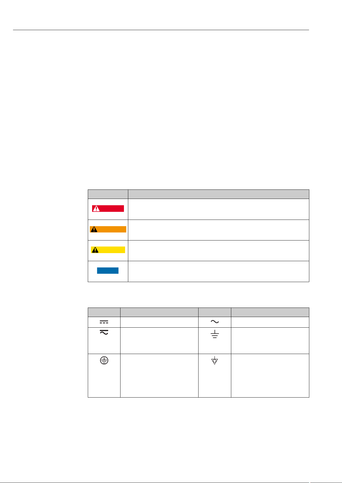
1.2.1 Safety symbols
Symbol Meaning
DANGER!
This symbol alerts you to a dangerous situation. Failure to avoid this situation will result in
serious or fatal injury.
WARNING!
This symbol alerts you to a dangerous situation. Failure to avoid this situation can result in
serious or fatal injury.
CAUTION!
This symbol alerts you to a dangerous situation. Failure to avoid this situation can result in
minor or medium injury.
NOTE!
This symbol contains information on procedures and other facts which do not result in
personal injury.
1.2.2 Electrical symbols
Symbol Meaning Symbol Meaning
Direct current Alternating current
Direct current and alternating current Ground connection
Protective ground connection
A terminal which must be connected
to ground prior to establishing any
other connections.
A grounded terminal which, as far as
the operator is concerned, is
grounded via a grounding system.
Equipotential connection
A connection that has to be connected
to the plant grounding system: This
may be a potential equalization line
or a star grounding system depending
on national or company codes of
practice.
6 Endress+Hauser
Page 7

Ecograph T, RSG35 Document information
,…,
,…,
-
.
1.2.3 Symbols for certain types of information
Symbol Meaning
Permitted
Procedures, processes or actions that are permitted.
Preferred
Procedures, processes or actions that are preferred.
Forbidden
Procedures, processes or actions that are forbidden.
Tip
Indicates additional information.
Reference to documentation
Reference to page
Reference to graphic
Series of steps
Result of a step
Help in the event of a problem
Visual inspection
1.2.4 Symbols in graphics
Symbol Meaning
1, 2, 3,... Item numbers
Series of steps
A, B, C, ... Views
A-A, B-B, C-C, ... Sections
Flow direction
A0013441
Hazardous area
Indicates a hazardous area.
A0011187
Safe area (non-hazardous area)
Indicates a non-hazardous area.
A0011188
1.3 Terminology
To improve clarity, abbreviations or synonyms are used in these instructions for the
following terms:
• Endress+Hauser:
Term used in these instructions: "Manufacturer" or "Supplier"
• Ecograph T RSG35:
Term used in these instructions: "Device" or "Measuring device"
1.4 Registered trademarks
Modbus
Registered trademark of SCHNEIDER AUTOMATION, INC.
Endress+Hauser 7
®
Page 8

Basic safety instructions Ecograph T, RSG35
Internet Explorer®, Excel
Registered trademarks of the Microsoft Corporation
Mozilla Firefox
Registered trademark of the Mozilla Foundation
®
Opera
Registered trademark of Opera Software ASA.
Google Chrome
Registered trademark of Google INC.
®
TM
TM
2 Basic safety instructions
Reliable and safe operation of the device is guaranteed only if the user reads these
Operating Instructions and complies with the safety instructions they contain.
2.1 Requirements concerning the staff
The personnel for installation, commissioning, diagnostics and maintenance must fulfill
the following requirements:
Trained, qualified specialists: must have a relevant qualification for this specific
‣
function and task
Are authorized by the plant owner/operator
‣
Are familiar with federal/national regulations
‣
Before beginning work, the specialist staff must have read and understood the
‣
instructions in the Operating Instructions and supplementary documentation as well as
in the certificates (depending on the application)
Following instructions and basic conditions
‣
The operating personnel must fulfill the following requirements:
Being instructed and authorized according to the requirements of the task by the
‣
facility's owner-operator
Following the instructions in these Operating Instructions
‣
2.2 Designated use
This device is designed for the electronic acquisition, display, recording, analysis, remote
transmission and archiving of analog and digital input signals in non-hazardous areas.
• The manufacturer accepts no liability for damages resulting from incorrect use or use
other than that designated. It is not permitted to convert or modify the device in any
way.
• The device is designed for installation in a panel and must only be operated in an
installed state.
2.3 Workplace safety
For work on and with the device:
Wear the required personal protective equipment according to federal/national
‣
regulations.
2.4 Operational safety
Risk of injury.
Operate the device in proper technical condition and fail-safe condition only.
‣
The operator is responsible for interference-free operation of the device.
‣
8 Endress+Hauser
Page 9

Ecograph T, RSG35 Product description
Conversions to the device
Unauthorized modifications to the device are not permitted and can lead to unforeseeable
dangers.
If, despite this, modifications are required, consult with the manufacturer.
‣
Repair
To ensure continued operational safety and reliability,
Carry out repairs on the device only if they are expressly permitted.
‣
Observe federal/national regulations pertaining to repair of an electrical device.
‣
Use original spare parts and accessories from the manufacturer only.
‣
Hazardous area
To eliminate a danger for persons or for the facility when the device is used in the
hazardous area (e.g. explosion protection, pressure vessel safety):
Based on the nameplate, check whether the ordered device is permitted for the
‣
intended use in the hazardous area.
Observe the specifications in the separate supplementary documentation that is an
‣
integral part of these Instructions.
2.5 Product safety
This measuring device is designed in accordance with good engineering practice to meet
state-of-the-art safety requirements, has been tested, and left the factory in a condition in
which it is safe to operate.
It meets general safety standards and legal requirements. It also complies with the EC
directives listed in the device-specific EC Declaration of Conformity. The manufacturer
confirms this by affixing the CE mark to the device.
2.6 Safety information for table version (option)
• The mains plug should only be inserted into a socket with a ground contact.
• The protective effect may not be suspended by an extension cable without a protective
ground.
• Relay outputs: U (max) = 30 V
(AC)/60 V (DC).
eff
2.7 IT security
The manufacturer only provides a warranty if the device is installed and used as described
in the Operating Instructions. The device is equipped with security mechanisms to protect
it against any inadvertent changes to the device settings.
IT security measures in line with operators' security standards and designed to provide
additional protection for the device and device data transfer must be implemented by the
operators themselves.
3 Product description
3.1 Product design
This device is best suited for the electronic acquisition, display, recording, analysis, remote
transmission and archiving of analog and digital input signals.
Endress+Hauser 9
Page 10

Incoming acceptance and product identification Ecograph T, RSG35
1
2
3
4
5
6
7
35 VA
The device is intended for installation in a panel or cabinet. There is also the option of
operating it in a table-mounted or field-mounted housing.
4 Incoming acceptance and product
identification
4.1 Incoming acceptance
On receipt of the goods, check the following points:
• Is the packaging or the content damaged?
• Is the delivery complete? Compare the scope of delivery against the information on your
order form.
4.2 Scope of delivery
The scope of delivery of the device comprises:
• Device (with terminals, as per order)
• 2 fastening clips
• USB cable
• Optional: Industrial grade SD card (card is located in the SD slot behind the flap on the
front of the housing)
• "Field Data Manager (FDM)" analysis software on DVD (Essential, Demo or Professional
version, depending on order)
• "FieldCare Device Setup / DeviceCare" configuration software on DVD
• Delivery note
• Multilanguage Brief Operating Instructions, hard copy
4.3 Product identification
4.3.1 Nameplate
Compare the nameplate with the following diagram:
1 Device nameplate (example)
1 Device tag
2 Order code, serial number, extended order code
3 Power supply, mains frequency
4 Maximum power consumption
10 Endress+Hauser
5 Temperature range
6 Software version; MAC address
7 Device approvals
A0019299
Page 11

Ecograph T, RSG35 Installation
4.4 Storage and transport
Compliance with the permitted environmental and storage conditions is mandatory. For
precise specifications, see the "Technical data" section→ 63 of the Operating
Instructions.
Please note the following:
• Pack the device so that is protected against impact for storage and transport. The
original packaging provides optimum protection.
• The permitted storage temperature is –20 to +60 °C (–4 to +140 °F).
5 Installation
5.1 Mounting requirements
NOTICE
Overheating due to buildup of heat in the device
To avoid heat buildup, please always ensure that the device is sufficiently cooled.
‣
The device is designed for use in a panel in non-hazardous areas.
• Ambient temperature range–10 to +50 °C (14 to 122 °F)
• Climate class as per IEC 60654-1: Class B2
• Degree of protection: IP65, NEMA 4 at front / IP20 housing at rear
5.1.1 Installation dimensions
Please observe the installation depth of approx. 158 mm (6.22 in) for the device incl.
terminals and fastening clips.
• Panel cutout: 138 to 139 mm (5.43 to 5.47 in) x 138 to 139 mm (5.43 to 5.47 in)
• Panel strength: 2 to 40 mm (0.08 to 1.58 in)
• Angle of vision: from the midpoint axis of the display, 75° to the left and right, 65° above
and below.
• A minimum distance of 15 mm (0.59 in) mm (inch) between the devices must be
observed if aligning the devices in the Y-direction (vertically above one another). A
minimum distance of 10 mm (0.39 in) mm (inch) between the devices must be observed
if aligning the devices in the X-direction (horizontally beside one another).
• Securing to DIN 43 834
5.2 Mounting the measuring device
Mounting tool: For installation in the panel, all you need is a screwdriver.
Endress+Hauser 11
Page 12

Installation Ecograph T, RSG35
144 (5.67)
144 (5.67)
141 (5.55)
17 (0.67)
34
(1.34)
X
Y
A0019301
2 Panel mounting and dimensions in mm (Inch)
1. Push the device through the panel cutout from the front. To avoid heat buildup,
maintain a distance of > 15 mm (>0.59 in) from walls and other devices.
2. Hold the device level and hang the fastening clips in the openings (1 x left, 1 x right).
3. Evenly tighten the screws on the fasting clip using a screwdriver to guarantee a
secure seal to the control panel (torque 100 Ncm).
5.3 Post-mounting check
• Is the sealing ring undamaged?
• Does the seal run all around the housing collar?
• Are the threaded rods properly tightened?
• Is the device fixed firmly in the center of the control panel cutout?
12 Endress+Hauser
Page 13

Ecograph T, RSG35 Electrical connection
6 Electrical connection
6.1 Connection conditions
WARNING
L
Danger! Electric voltage!
The entire connection of the device must take place while the device is de-energized.
‣
The mixed connection of safety extra-low voltage and dangerous contact voltage to the
‣
relay is not permitted.
Apart from the relays and the supply voltage, only energy-limited circuits according to
‣
IEC/EN 61010-1 may be connected.
Danger if protective ground is disconnected
The ground connection must be made before all other connections.
‣
NOTICE
Cable heat load
Use suitable cables for temperatures of 5 °C (9 °F) above ambient temperature.
‣
Incorrect supply voltage can damage the device or cause malfunctions
Before commissioning the device, make sure that the supply voltage matches the
‣
voltage specifications on the nameplate.
Check emergency shutdown for device
Provide suitable switch or circuit breaker in building installation. This switch must be
‣
provided close to the device (within easy reach) and marked as a circuit breaker.
Protect the device from overload
Provide overload protection (nominal current = 10 A) for power cable.
‣
Incorrect wiring may result in the device being destroyed
Note terminal designation on the rear of the device.
‣
Energy-rich transients in the case of long signal lines
Install suitable overvoltage protection (e.g. E+H HAW562) upstream.
‣
6.2 Connection instructions
6.2.1 Cable specification
Cable specification, spring terminals
All connections on the rear of the device are designed as pluggable screw or spring
terminal blocks with reverse polarity protection. This makes the connection very quick and
easy. The spring terminals are unlocked with a slotted screwdriver (size 0).
Please note the following when connecting:
• Wire cross-section, auxiliary voltage output, digital I/O and analog I/O: max. 1.5 mm
(14 AWG) (spring terminals)
• Wire cross-section, mains: max. 2.5 mm2 (13 AWG) (screw terminals)
• Wire cross-section, relays: max. 2.5 mm2 (13 AWG) (spring terminals)
• Stripping length: 10 mm (0.39 in)
No ferrules must be used when connecting flexible wires to spring terminals.
Shielding and grounding
Optimum electromagnetic compatibility (EMC) can only be guaranteed if the system
components and, in particular, the lines - both sensor lines and communication lines - are
2
Endress+Hauser 13
Page 14

Electrical connection Ecograph T, RSG35
5
6
9
1
Frequency
shielded and the shield forms as complete a cover as possible. A shielded line must be used
for sensor lines that are longer than 30 m. A shield coverage of 90% is ideal. In addition,
make sure not to cross sensor lines and communication lines when routing them. Connect
the shield as often as possible to the reference ground to ensure optimum EMC protection
for the different communication protocols and the connected sensors.
To comply with requirements, three different types of shielding are possible:
• Shielding at both ends
• Shielding at one end on the supply side with capacitance termination at the device
• Shielding at one end on the supply side
Experience shows that the best results with regard to EMC are achieved in most cases in
installations with one-sided shielding on the supply side (without capacitance termination
at the device). Appropriate internal device wiring measures must be taken to allow
unrestricted operation when EMC interference is present. These measures have been
taken into account for this device. Operation in the event of disturbance variables as per
NAMUR NE21 is thus guaranteed.
Where applicable, national installation regulations and guidelines must be observed
during the installation! Where there are large differences in potential between the
individual grounding points, only one point of the shielding is connected directly with the
reference ground.
If the shielding of the cable is grounded at more than one point in systems without
potential matching, mains frequency equalizing currents can occur. These can damage
the signal cable or significantly impact signal transmission. In such cases the shielding
of the signal cable is to be grounded on one side only, i.e. it may not be connected to
the ground terminal of the housing. The shield that is not connected should be
insulated!
6.3 Connecting the measuring device
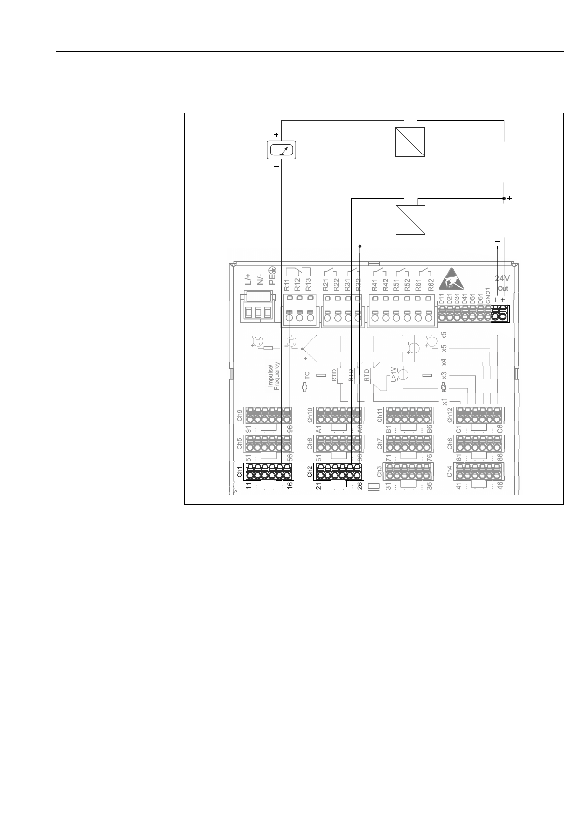
6.3.1 Terminal assignment on the rear of the device
A0019304
3 Terminals on the rear of the device
14 Endress+Hauser
Page 15

Ecograph T, RSG35 Electrical connection
6.3.2 Supply voltage
Power unit type Terminal
A0019103
100-230 VAC L+ N- PE
Phase L Zero conductor N Ground
24 V AC/DC L+ N- PE
Phase L or + Zero conductor N or - Ground
6.3.3 Relays
Type Terminal (max. 250 V, 3 A)
Alarm relay 1 R11 R12 R13
Changeover
contact
Normally
closed contact
1)
(NC)
Normally open
contact (NO)
2)
Relay 2 to 6 Rx1 Rx2
Switching contact Normally open
1) NC = normally closed (breaker)
2) NO = normally open (maker)
6.3.4 Digital inputs; auxiliary voltage output
Type Terminal
Digital input
1 to 6
Auxiliary
voltage
output, not
stabilized,
max. 250
mA
D11 to D61 GND1
Digital input 1 to 6
(+)
Ground (-) for digital
inputs 1 to 6
24V Out - 24V Out +
- Ground + 24V (±15%)
contact (NO
2)
A0019103
)
A0019103
Endress+Hauser 15
Page 16
Electrical connection Ecograph T, RSG35
Chx
x1
x2
x3
x4
x5
x6
6.3.5 Analog inputs
The first digit (x) of the two-digit terminal number corresponds to the associated channel:
Type Terminal
A0019303
x1 x2 x3 x4 x5 x6
Current/pulse/frequency
1)
input
Voltage > 1V (+) (-)
Voltage ≤1V (+) (-)
Resistance thermometer
RTD (2-wire)
Resistance thermometer
RTD (3-wire)
Resistance thermometer
RTD (4-wire)
Thermocouples TC (+) (-)
(A) (B)
(A) b (sense) (B)
(A) a (sense) b (sense) (B)
(+) (-)
1) If a universal input is used as a frequency or pulse input and the voltage is >2.5 V, a series resistor must be
used in series connection with the voltage source. Example: 1.2 kΩ series resistor at 24 V
16 Endress+Hauser
Page 17
Ecograph T, RSG35 Electrical connection
Frequency
Out: max. 250 mA
_
+
+
-
Y
+
_
+
-
Y
I
I
1
2
3
6.3.6 Connection example: Auxiliary voltage output as transmitter power supply for 2-wire sensors
4 Connecting auxiliary voltage output when using as a transmitter power supply for 2-wire sensors in the
current measuring range. (When connecting channel CH3-12, see pin assignment CH1-2.)
1 Sensor 1 (e.g. Cerabar from Endress+Hauser)
2 Sensor 2
3 External indicator (optional) (e.g. RIA16 from Endress+Hauser)
A0020259
Endress+Hauser 17
Page 18

Electrical connection Ecograph T, RSG35
Frequency
_
+
+
_
Out: max. 250 mA
+
-
Y
+
-
I
24V
+
-
Y
+
-
I
24V
1
2
3
6.3.7 Connection example: Auxiliary voltage output as transmitter power supply for 4-wire sensors
5 Connecting auxiliary voltage output when using as a transmitter power supply for 4-wire sensors in the
1 Sensor 1 (e.g. temperature switch TTR31 from Endress+Hauser)
2 Sensor 2
3 External indicator (optional) (e.g. RIA16 from Endress+Hauser)
6.3.8 Option: RS232/RS485 interface (rear of device)
current measuring range. (When connecting channel CH3-12, see pin assignment CH1-2.)
A0020260
Use shielded signal lines for serial interfaces!
A combined RS232/RS485 connection is available on a shielded SUB D9 socket at the rear
of the device. This can be used for data transfer and to connect a modem. For
communication via modem, we recommend an industrial modem with a watchdog
function.
18 Endress+Hauser
Page 19

Ecograph T, RSG35 Electrical connection
Further units
Termination
resistor
(typical 120 )Ω
To PC: Cable with
9 pol. Sub-D plug
RxD - 3 GND - 5
TxD - 2
To PC: Cable with
25 pol. Sub-D
plug
To modem: Cable with
9 pol. Sub-D socket
To modem: Cable with
25 pol. Sub-D socket
A0019305-EN
Type Pin of the SUB-D9 socket
1 2 3 4 5 6 7 8 9
RS232
assignment
RS485
assignment
TxD (data
output)
RxD (data
input)
GND
GND RxD/TxD – RxD/TxD +
Unoccupied connections should be left empty.
Maximum cable length:
RS232: 2 m (6.6 ft)
RS485: 1000 m (3280 ft)
Only one interface can be used at any one time (RS232 or RS485).
6.3.9 Ethernet connection (rear of device)
The Ethernet interface can be used to integrate the device via a hub or switch into a PC
network (TCP/ IP Ethernet). A standard patch cable (e.g. CAT5E) can be used for the
connection. Using DHCP, the device can be fully integrated into an existing network
without the need for additional configuration. The device can be accessed from every PC in
the network.
• Standard: 10/100 Base T/TX (IEEE 802.3)
• Socket: RJ-45
• Max. cable length: 100 m
• Galvanic isolation; testing voltage: 500 V
Endress+Hauser 19
Page 20
Electrical connection Ecograph T, RSG35
6 4
3
2
1
5
7
8
9
10
11
12
Meaning of the LEDs
Beneath the Ethernet connection (see rear of device) there are two light emitting diodes
which indicate the status of the Ethernet interface.
• Yellow LED: link signal; is lit when the device is connected to a network. If this LED is not
illuminated then communication is impossible.
• Green LED: Tx/Rx; flashes irregularly if the device is transmitting or receiving data.
6.3.10 Option: Ethernet Modbus TCP slave
The Modbus TCP interface is used to connect to higher-ranking SCADA systems (Modbus
master) to transmit all measured values and process values. Up to 12 analog inputs and 6
digital inputs can be transmitted via Modbus and stored in the device. Form a physical
point of view, the Modbus TCP interface is identical to the Ethernet interface.
6.3.11 Option: Modbus RTU slave
The Modbus RTU (RS485) interface is galvanically isolated (testing voltage: 500 V) and is
used to connect to higher-ranking systems to transmit all measured values and process
values. Up to 12 analog inputs and 6 digital inputs can be transmitted via Modbus and
stored in the device. Connection is via the combined RS232/RS485 interface.
Modbus TCP and Modbus RTU cannot be used at the same time.
6.3.12 Connections at front of device
6 Front of device with open flap
1 Navigator
2 LED at SD slot. Orange LED lights up or flashes when the device writes to or reads from the SD card.
3 Slot for SD card
4 USB B socket "Function" e.g. to connect to PC or laptop
5 Green LED lit: power supply present
6 USB A socket "Host" e.g. for USB memory stick or external keyboard
7-12 For a description of the displays, see the "Operability" section
20 Endress+Hauser
A0019501
Page 21

Ecograph T, RSG35 Electrical connection
USB connection type A (host)
A USB 2.0 port is available on a shielded USB A socket at the front of the device. A USB
stick, for example, can be connected to this interface as a storage medium. An external
keyboard or USB hub may also be connected.
USB connection type B (function)
A USB 2.0 port is available on a shielded USB B socket at the front of the device. This can
be used to connect the device for communication with a laptop, for example.
USB-2.0 is compatible with USB-1.1 or USB-3.0, i.e. communication is possible.
Information on USB devices
The USB devices are detected by the "plug-and-play" function. If several devices of the same
type are connected, only the USB device that was connected first is available. Settings for
the USB devices are made in the setup. A maximum of 8 external USB devices (incl. USB
hub) can be connected if they do not exceed the maximum load of 500 mA. If overloaded,
the corresponding USB devices are automatically disabled.
Requirements with regard to an external USB hub
The USB devices are detected by the "plug-and-play" function. If several devices of the same
type are connected, only the USB device that was connected first is available. Settings for
the USB devices are made in the setup. A maximum of 8 external USB devices (incl. USB
hub) can be connected if they do not exceed the maximum load of 500 mA. If overloaded,
the corresponding USB devices are automatically disabled.
Requirements with regard to the USB stick
There is no guarantee that all manufacturers' USB sticks will function faultlessly. That is
why an industrial grade SD card is recommended to ensure the reliable recording of data.
→ 61
The USB stick must be formatted to FAT or FAT32. NTFS format is not readable. The
system supports only USB sticks with max. 32 GB.
The USB stick must not be connected to the device via a USB hub. Interference from
other USB devices may result in data loss.
Requirements with regard to an external USB keyboard
The system only supports keyboards which can be addressed using generic drivers (HID
keyboard - Human Interface Device). Special keys are not supported (e.g. Windows keys).
Users can only enter characters that are available in the entry character set of the device.
All unsupported characters are rejected. It is not possible to connect a wireless keyboard.
The following keyboard layouts are supported: DE, CH, FR, USA, USA International, UK, IT.
See setting under "Setup -> Advanced setup -> System -> Keyboard layout".
Requirements for the SD card
Industrial grade SD-HC cards with max. 32 GB are supported.
Use only the industrial grade SD cards described in the "Accessories" section of the
Operating Instructions. These have been tested by the manufacturer and guaranteed
to function faultlessly in the device. → 61
The SD card must be formatted to FAT or FAT32. NTFS format is not readable.
Endress+Hauser 21
Page 22

Electrical connection Ecograph T, RSG35
6.4 Post-connection check
Device condition and specifications Notes
Are cables or the device damaged? Visual inspection
Electrical connection Notes
Does the supply voltage match the specifications on the nameplate? -
Are all terminals firmly engaged in their correct slot? -
Are the mounted cables strain-relieved? -
Are the power supply and signal cables correctly connected? See connection diagram and
rear of device.
22 Endress+Hauser
Page 23
Ecograph T, RSG35 Operation options
System
Communication
Operation
Setup
Advanced setup
Diagnostics
Measured Values
Operator
Maintenance
Diagnostics list
Outputs
Output
Event logbook
Device information
Simulation
Change group
SD card/USB stick
History
Change date/time
Date/time setup
Change display mode
Adjust brightness
Security
External memory
Messages
Screen saver
Device options,...
Inputs
Universal inputs
Digital inputs
Relaiy 1 - 6
Ethernet
Serial interface
Modbus Slave
Application
Maths
Signal analysis
Limits
Signal groups
E-mail
Initialize modem
Signal analysis
WebDAV Client
Lock operation
Search in trace
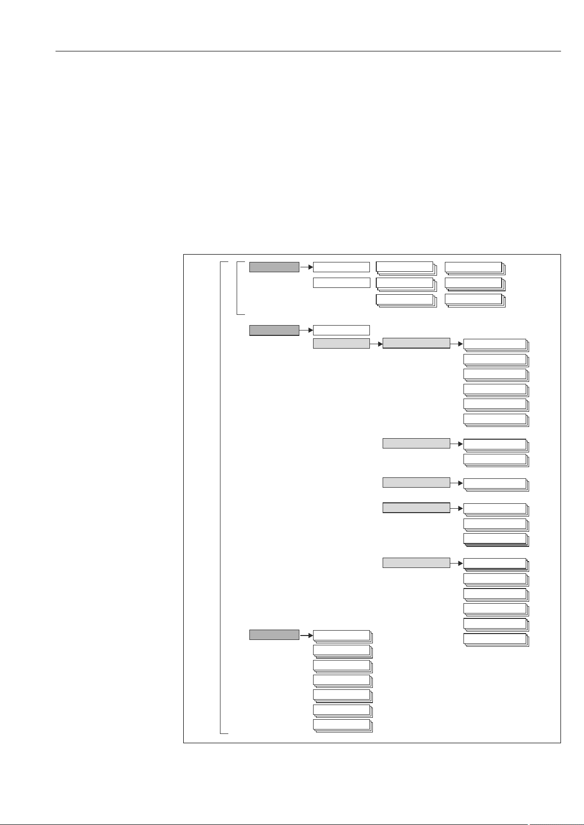
7 Operation options
7.1 Overview of operation options
The device can be operated directly onsite with the Navigator and USB keyboard/mouse or
via interfaces (serial, USB, Ethernet) and operating tools (Web server, FieldCare/
DeviceCare configuration software).
7.2 Structure and function of the operating menu
7.2.1 Operating menu for operators and maintenance personnel
Endress+Hauser 23
A0019594-EN
Page 24
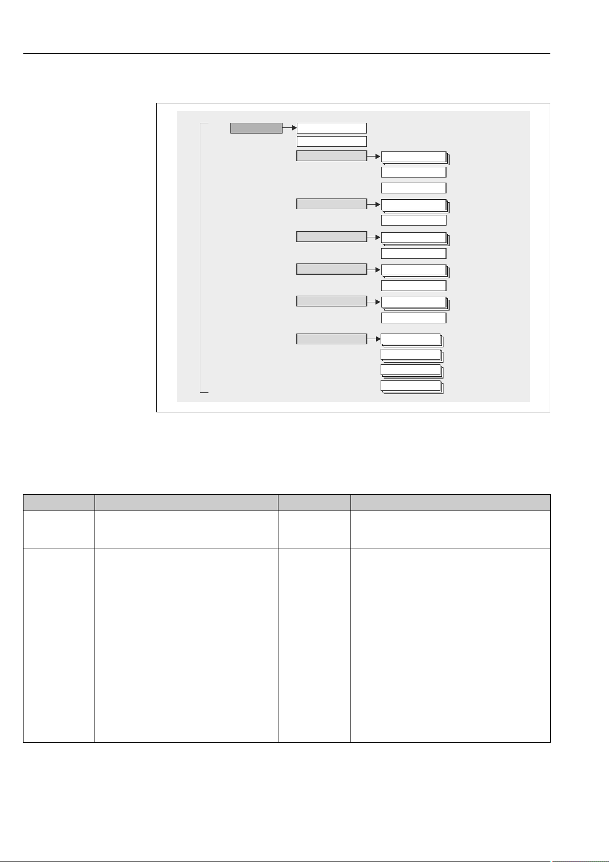
Operation options Ecograph T, RSG35
Expert
Diagnostics
Expert
Outputs
Enter Access code
System
Diagnosis list
(see before)
+Clear memory
+Expert functions
Inputs
Communication
Application
Event logbook
Device information
Simulation
(see before)
(see before)
(see before)
Direct Access
+Expert functions
+Expert functions
+Expert functions
+Expert functions
(see before)
7.2.2 Operating menu for experts
7.2.3 Submenus and users
Certain parts of the menu are assigned to certain user roles. Each user role corresponds to
typical tasks within the lifecycle of the device.
User role Typical tasks Menu Content/meaning
Operator Tasks during operation:
• Configuration of the display.
• Reading measured values.
Maintenance Commissioning:
• Configuration of the measurement.
• Configuration of data processing.
"Operation" Contains all the parameters that are required in
ongoing operation: configuration of the measured value
display (displayed values, display format, etc.).
"Setup" Contains all parameters for commissioning:
• Change date/time
• "Advanced setup" submenu
Contains additional submenus and parameters:
– System: Basic settings required for operating the
device.
– Inputs: Settings for analog and digital inputs.
– Outputs: Setup required only if outputs (e.g.
relays) are to be used.
– Communication: Settings required if you are
using the USB, RS232, RS485 or Ethernet
interface of the device (PC operation, serial data
export, modem operation, etc.).
– Application: Define different application-specific
settings (e.g. group settings, limit values, etc.).
Once values have been set for these parameters, the
measurement should generally be completely
configured.
A0019596-EN
24 Endress+Hauser
Page 25

Ecograph T, RSG35 Operation options
User role Typical tasks Menu Content/meaning
Fault elimination:
• Diagnosing and eliminating process errors.
• Interpretation of device error messages and
correcting associated errors.
Expert Tasks that require detailed knowledge of the
function of the device:
• Commissioning measurements under difficult
conditions.
• Optimal adaptation of the measurement to
difficult conditions.
• Detailed configuration of the communication
interface.
• Error diagnostics in difficult cases.
"Diagnostics" Contains all parameters for detecting and analyzing
errors:
• Diagnosis list
All diagnosis messages are listed in chronological
order.
• Event logbook
Events such as limit value violations and power
failures are listed in chronological order.
• Device information
Displays important device information (e.g. serial
number, firmware version, device options for
hardware and software, memory information, etc.).
• Measured values
Display of current measured values of device.
• Outputs
Displays the current status of the outputs e.g. switch
status of relay outputs.
• Simulation
Various functions/signals can be simulated for test
purposes here.
Note: In Simulation mode, normal recording of the
measured values is interrupted and the intervention
is logged in the event log.
• Initialize modem
Initializes the modem connected to the serial
interface (for automatic call answering).
"Expert" Contains all parameters of the device (including those
that are already in one of the other menus). The expert
menu is protected by a code. Factory setting: 0000. This
menu is structured according to the function blocks of
the device:
• "System" submenu
Contains all higher-order device parameters that do
not concern the measurement or measured value
communication.
• "Inputs" submenu
Contains all parameters for configuring the analog
and digital inputs.
• "Output" submenu
Contains all parameters for configuring the outputs
(e.g. relays).
• "Communication" submenu
Contains all parameters for configuring the
communication interfaces.
• "Application" submenu
Contains all parameters for configuring applicationspecific settings (e.g. group settings, limit values
etc.).
• "Diagnostics" submenu
Contains all parameters needed to detect and
analyze operational errors.
Endress+Hauser 25
Page 26
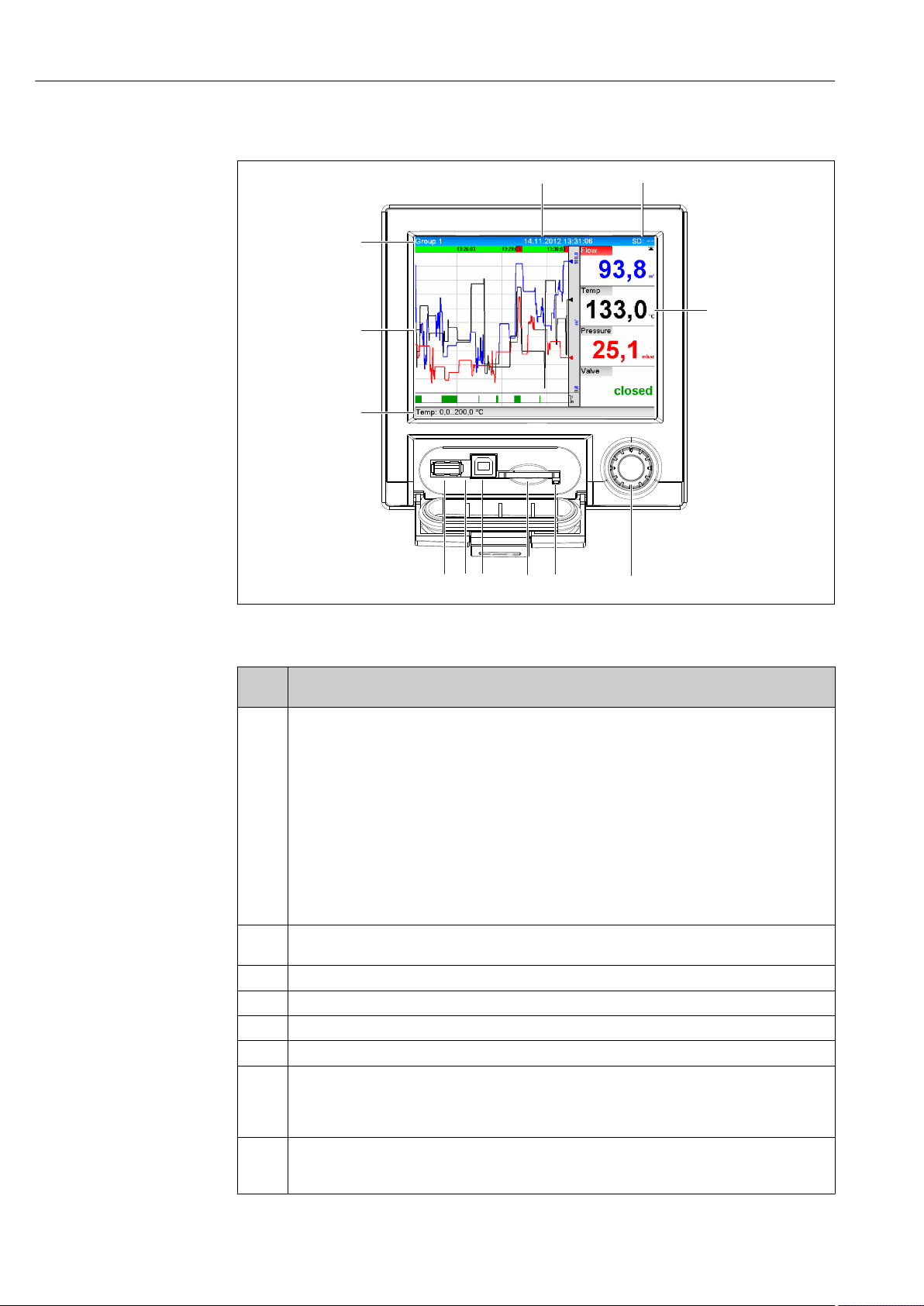
Operation options Ecograph T, RSG35
6 4
3
2
1
5
7
8
9
10
11
12
7.3 Measured value display and operating elements
A0020602-EN
7 Front of device with open flap
Item
No.
1 "Navigator": jog/shuttle dial for operating with additional press/hold function.
2 LED at SD slot. Orange LED lit when the device writes to the SD card or reads it.
3 Slot for SD card
4 USB B socket "Function" e.g. to connect to PC or laptop
5 Green LED lit: power supply present
6 USB A socket "Host" e.g. for USB memory stick or external keyboard
7 In display mode: alternating status display (e.g. set zoom range) of the analog or digital inputs in the
8 In display mode: window for measured value display (e.g. curve display).
Operating function (display mode = display of measured values)
(Setup mode = operating in the Setup menu)
'
In display mode: turn the dial to switch between the various signal groups. Press the dial to display the
main menu.
'
In setup mode or in a selection menu: turn the dial anticlockwise to move the bar or the cursor
upwards or counterclockwise, changes the parameter. Turning clockwise moves the bar or cursor
down or clockwise, changes parameter.
Press briefly (<2 sec.) = Select highlighted function, parameter change starts (ENTER key).
Access online help: Press and hold Navigator (>3 sec.) to show information on the selected
function.
To quit the menu immediately, press and hold "Back" (>3 sec.) in the Navigator. The devices
switches to display mode.
Do not remove the SD card if the LED is lit! Risk of data loss!
appropriate color of the channel.
'
In setup mode: different information can be displayed here depending on the display type.
'
In setup mode: display of operating menu
26 Endress+Hauser
Page 27

Ecograph T, RSG35 Operation options
Item
No.
9 In display mode: current group name, type of evaluation
10 In display mode: displays current date/time
11 In display mode: alternating display indicating the percentage space on the SD card or USB stick that
12 In display mode: display of current measured values and the status in the event of an error/alarm
Operating function (display mode = display of measured values)
(Setup mode = operating in the Setup menu)
'
In setup mode: name of the current operating item (dialog title)
In setup mode: --
has already been used.
Status symbols are also displayed in alternation with the memory information (see the following
table).
'
In setup mode: the current "direct access" operating code is displayed
condition. In the case of counters, the type of counter is displayed as a symbol (see the following
table).
If a measuring point has limit value status, the corresponding channel identifier is highlighted
in red (quick detection of limit value violations). During a limit value violation and device
operation, the acquisition of measured values continues uninterrupted.
7.4 Display representation of symbols used in operation
Item
No.
8,12 Symbols for counters:
8, 12 Channel-related symbols:
11 Symbol for status signals:
Function Description
å1
åD
åM
åY
å
Interim analysis/ external analysis
Daily analysis
Monthly analysis
Annual analysis
Totalizer
Violation of lower limit value
Violation of upper limit value or limit value on counter
Violation of upper and lower limit values at the same time
"Out of specification"
e.g. input signal too high/low
Error message "Failure detected"
An operating error has occurred. The measured value is no longer valid (e.g.
a channel not displayed in the current group is defective).
"Maintenance required"
Maintenance is required. The measured value is still valid.
Error, measured value not displayed.
Possible causes: Sensor / input error, line break, invalid value, input signal
too high/low
"Device locked"
Setup is locked via a control input. Disable setup lock via a control input.
"Out of specification"
The device is being operated outside its technical specifications (e.g. during
startup or cleaning).
"Function check"
The device is in Service mode.
Endress+Hauser 27
Page 28

Operation options Ecograph T, RSG35
Item
No.
7 "Historical data"
Function Description
"Maintenance required"
Maintenance is required. The measured value is still valid.
Error message "Failure detected"
An operating error has occurred. The measured value is no longer valid (e.g.
a channel not displayed in the current group is defective).
"External communication"
The device is communicating externally (e.g. via Modbus).
SIM "Simulation"
Simulation is active.
Historical data are currently shown on screen.
7.4.1 Symbols in operating menus
Symbol for setup
Symbol for diagnostics
Symbol for expert setup
Back
Use the "Back" function, which can be found at the bottom of each menu/submenu, to move up
a level in the menu structure.
To quit the menu immediately, press and hold "Back" (>3 sec.) in the Navigator. The
devices switches to display mode.
7.4.2 Symbols in the event logbook
Setup changes
Power on
Power off
Limit value on
Limit value off
1 Digital on (on/off message)
0 Digital off (on/off message)
Service
Texts saved / comments added
Acknowledging message
Back
Continue searching
7.5 Entering text and numbers (virtual keyboard)
A virtual keyboard is available for entering text and numbers. This is opened automatically
if needed. Here, turn the navigator to select the corresponding character and press the
navigator to accept it.
The following characters are available for entering free text:
28 Endress+Hauser
Page 29

Ecograph T, RSG35 Operation options
0-9 a-z A-Z = + - * / \ 2 3 ¼ ½ ¾ ( ) [ ] < > { } I ? ! ` " ' ^ % ° . , : _ µ & # $ € @ § £ ¥ ~
← Jump one position to the left.
If this symbol is selected, the cursor jumps one position to the left.
→ Jump one position to the right.
If this symbol is selected, the cursor jumps one position to the right.
←x Delete backwards.
If this symbol is selected, the character to the left of the cursor position is deleted.
x→ Delete forwards.
If this symbol is selected, the character to the right of the cursor position is deleted.
Delete all.
if this symbol is selected, the entire entry is deleted.
Reject entry.
If this symbol is selected, the entry is rejected and you quit editing mode. The previously set text
remains.
Accept entry.
If this symbol is selected, the entry is applied at the position specified by the user, and you quit
editing mode.
7.6 Channel color assignment
Channel color assignment is performed in the main menu under "Setup -> Advanced
setup -> Application -> Signal groups -> Group x". 8 predefined colors are available per
group and can be assigned to the desired channels.
7.7 Access to the operating menu via the local display
Using the "Navigator" (jog/shuttle dial with additional press function), all settings can be
made directly onsite at the device.
7.8 Device access via operating tools
7.8.1 Field Data Manager (FDM) analysis software (SQL database support)
The PC analysis software offers external, centralized data management with visualization
for recorded data. The analysis software enables the complete archiving of all measuring
point data e.g. measured values, diagnostic events and protocols. The analysis software
stores data in an SQL database. The database can be operated locally or in a network
(client / server). Access is via RS232/RS485, USB or Ethernet interface (network).
Function scope:
• Export of saved data (measured values, analyses, event log)
• Visualization and processing of saved data (measured values, analyses, event log)
• Safe archiving of exported data in a SQL database
The following versions of the software are available:
• Essential version (free, with limited functionalities)
• Professional version (see accessories → 61)
• Demo version (time-limited Professional version)
An "Essential" version of the analysis software is supplied with the device.
For details, see the Operating Instructions on the analysis software DVD provided.
Endress+Hauser 29
Page 30

Operation options Ecograph T, RSG35
7.8.2 Web server
A web server is integrated into the device. This makes the current measured values of the
device available in real time. Access is via an Ethernet interface from a PC in the network
via the standard browser. The installation of additional software is not required.
The Web server offers the following range of functions:
• Display of current and historical data and measured value curves via a standard Web
browser → 38
• Easy configuration without additional installed software → 32
• Remote access to device and diagnostic information
7.8.3 OPC server (optional)
The OPC server makes it possible to access data on the device. These data are made
available to OPC clients in real time. The OPC server meets the requirements of the OPC
specifications regarding the supply of data to an OPC client. Access is via RS232/RS485,
USB or Ethernet interface (network). Communication takes place using automatic device
detection; the operator does not need to make any additional settings. The OPC server
enables the flexible and powerful exchange of data and is easy and convenient to use.
The following momentary values can be provided:
• Analog channels
• Digital channels
• Mathematics
• Totalizer
For details, see Operating Instructions BA00223R/09/xx
7.8.4 FieldCare/DeviceCare configuration software (included in the
delivery)
Function scope
The configuration software is an FDT/DTM-based system asset management tool. It can
configure all smart field devices in a system and helps you manage them. By using the
status information, it is also a simple but effective way of checking their status and
condition. Access is via USB or Ethernet interface (network).
Typical functions:
• Device configuration
• Loading and saving device data (upload/download)
• Documentation of the measuring point
For details, see the Operating Instructions on the configuration software DVD
provided
Overview of device description files (DTM)
Information and files are available free of charge at:
See online at: www.de.endress.com/fieldcare
30 Endress+Hauser
Page 31
Ecograph T, RSG35 System integration
8 System integration
8.1 Integrating the measuring device in the system
8.1.1 General notes
The device has (optional) fieldbus interfaces for exporting process values. Measured values
and statuses can also be transmitted to the device via fieldbus. Note: Counters cannot be
transferred.
Alarms or errors in the context of data transmission are displayed depending on the bus
system (e.g. status byte).
The process values are transferred in the same devices that are used for display at the
device.
8.1.2 Ethernet
Setup → Advanced setup → Communication → Ethernet
The IP address can be entered manually (fixed IP address) or assigned automatically using
DHCP.
The port for data communication is preset to 8000. The port can be changed in the Expert
→ Communication → Ethernet menu.
The following functions are implemented:
• Data communication with PC software (analysis software, configuration software, OPC
server)
• Web server
The following connections are possible at the same time:
• 1x Port 8000 (configuration software, OPC server or analysis software)
• 1x Port 8002 (OPC server only)
• 4x Modbus slave TCP
• 5x Web server
Ports can be changed!
As soon as the maximum number of connections has been reached, new connection
attempts are blocked until an existing connection has been terminated.
8.1.3 Modbus RTU/TCP slave
The device can be connected to a Modbus system via RS485 or Ethernet interface. The
general settings for the Ethernet connection are made in the Setup → Advanced setup →
Communication → Ethernet menu. Configuration for Modbus communication is done in
the Setup → Advanced setup → Communication → Modbus slave menu. Up to 12 analog
inputs and 6 digital inputs can be transmitted via Modbus and stored in the device.
Menu position RTU (RS485) Ethernet
Device address: 1 to 247 IP address manual or automatic
Baud rate: 9600/19200/38400/57600/115200 -
Parity: Even/Odd/None -
Stop bits: 1/2 -
Port: - 502
Endress+Hauser 31
Page 32

Commissioning Ecograph T, RSG35
Transfer of values
The actual Modbus TCP protocol is located between layer 5 to 6 in the ISO/OSI model.
To transfer a value, 3 registers of 2 bytes each (2-byte status + 4-byte float) or 5 registers
of 2 bytes each (2-byte status + 8-byte double) are used.
More detailed information about Modbus is provided in the supplementary
documentation.
9 Commissioning
9.1 Function check
Make sure that all post-connection checks have been carried out before putting your device
into operation:
• "Post-installation check" checklist .→ 12
• "Post-connection check" checklist .→ 22
9.2 Switching on the measuring device
Once the operating voltage is applied, the display lights up and the device is ready for
operation.
If you are commissioning the device for the first time, program the setup as described in
the following sections of the Operating Instructions.
If you are commissioning a device that is already configured or preset, the device starts
measuring immediately as defined in the settings. The values of the channels currently
activated are shown on the display.
Remove the protective film from the display as this would otherwise affect the
readability of the display.
9.3 Setting the operating language
Factory setting: English or ordered local language.
Calling the main menu, configuring the operating language:
1. Press the navigator
2. The main menu appears on the display with the "Sprache/Language" option
3. Change the default language setting: press the navigator, turn it to select the
preferred language and press the navigator again to accept the setting
4. Use "Back" or "ESC" to quit the main menu
The operating language has been changed.
Use the "Back" function, which can be found at the bottom of each menu/submenu,
to move up a level in the menu structure.
To quit the menu immediately and return to the measured value display, press and
hold "Back" (>3 sec.). The changes made are accepted and saved.
9.4 Configuring the measuring device (Setup menu)
Access to the setup is enabled when the device leaves the factory and can be locked in
various ways e.g. by entering a 4-digit access code or via role-based password protection.
32 Endress+Hauser
Page 33

Ecograph T, RSG35 Commissioning
When locked, basic settings can be checked but not changed. You can also use a PC to
commission or configure your device.
Device configuration options:
• Setup directly at the device
• Setup via SD card or USB stick by transferring the parameters stored on it
• Setup via Web server using Ethernet
• Setup via FieldCare/DeviceCare configuration software using USB interface or Ethernet
9.4.1 Step-by-step: to the first measured value
Procedure and necessary settings:
1. Check the date/time in the main menu under "Setup" and set it if necessary
2. Make settings for the interfaces and communication in the main menu under "Setup
-> Advanced setup -> Communication"
3. Create universal or digital inputs in the main menu under "Setup -> Advanced setup
-> Inputs -> Universal inputs/Digital inputs": Add input: select "Universal input
x" or "Digital input x" with which the input signal should be detected. Then select the
newly created input and configure it
4. Activate relays or analog outputs (optional) in the main menu under "Setup ->
Advanced setup -> Outputs"
5. Assign activated inputs to a group in the main menu under "Setup -> Advanced
setup -> Application -> Signal groups -> Group x"
6. Use "Back" or "ESC" to quit the main menu. The changes made are accepted and saved
The device is in the measured value display mode and displays the measured values.
9.4.2 Step-by-step: set or delete the limit values
Procedure for setting limit values:
1. Open the limit values in the main menu under "Setup -> Advanced setup ->
Application -> Limits"
2. Add a limit value: select "Yes"
3. Select and configure "Limit value x"
4. Use "Back" or "ESC" to quit the main menu. The changes made are accepted and saved
The device is in the measured value display mode and displays the measured values.
Procedure for deleting limit values:
1. Open the limit values in the main menu under "Setup -> Advanced setup ->
Application -> Limits"
2. Delete a limit value: select "Yes"
3. Select the limit value to be deleted from the list
4. Use "Back" or "ESC" to quit the main menu. The changes made are accepted and saved
The device is in the measured value display mode and displays the measured values.
9.4.3 Setup directly at the device
You can access the main menu by pressing the Navigator during operation. Turn the
Navigator to navigate through the available menus. When the desired menu is displayed,
press the Navigator to open the menu.
Endress+Hauser 33
Page 34

Commissioning Ecograph T, RSG35
In the "Setup" menu and in the "Advanced setup" submenu, you will find the most
important settings for the device:
Parameters Possible settings Description
Change date/time UTC time zone
dd.mm.yyyy hh:mm:ss
Advanced setup Advanced settings for the device e.g. system settings,
System Basic settings that are needed to operate the device,
Inputs Settings for analog and digital inputs
Outputs Settings only required if outputs (e.g. relays or
Communicati
on
Application Configure various application-specific settings (e.g.
Change the date and time
inputs, outputs, communication, application etc.
(e.g. date/ time, security, memory management,
messages, etc.)
analog outputs) are to be used
Settings required if the USB, RS232/RS485 or
Ethernet interface of the device is to be used (PC
operation, serial data export, modem operation, etc.)
The different interfaces (USB, RS232/RS485,
Ethernet) can be operated in parallel. However,
simultaneous use of the RS232 and RS485
interface is not possible.
group settings, limit values, etc.)
A detailed overview of all the operating parameters is provided in the appendix at the
end of the Operating Instructions. → 78
9.4.4 Setup via SD card or USB stick
An existing device configuration ("Setup data" *.DEH) from another Ecograph T RSG35 or
from FieldCare/DeviceCare can be uploaded directly to the device.
Import new setup directly at the device: The function used to load the setup data can be
found in the main menu under "Operation -> SD card (or USB stick) -> Load setup" ->
Select directory -> Next".
9.4.5 Setup via Web server
To configure the device via the Web server, connect the device via Ethernet to your PC.
Please observe the information and communication settings for Ethernet and the Web
server under .→ 31
To configure the device via a Web server, you must have Administrator or Service
access. ID and password administration is performed in the main menu under "Setup
-> Advanced setup -> Communication -> Ethernet -> Configuration Web server ->
Authentication".
Default value for ID: admin; Password: admin
Note: The password should be changed during commissioning!
Establishing a connection and setup
Procedure for setting up a connection:
1. Connect the device to the PC via Ethernet
2. Start the browser at the PC; open the Web server for the device by entering the IP
address: http://<ip-address> Note: Leading zeros in IP addresses must not be entered
(e.g. enter 192.168.1.11 instead of 192.168.001.011)
34 Endress+Hauser
Page 35

Ecograph T, RSG35 Commissioning
3. Enter ID and password, and confirm each by clicking "OK"
4. The Web server shows the instantaneous value display of the device. Click "Menu ->
Setup -> Advanced setup" in the Web server function bar
5. Starting configuration
Continue with device configuration in accordance with the Operating Instructions for the
device. The complete Setup menu i.e. all of the parameters listed in the Operating
Instructions, can also be found on the Web server. After configuration, accept the setup
with "Save settings".
Procedure to establish a direct connection via Ethernet (point-to-point connection):
→ 38
NOTICE
Undefined switching of outputs and relays
During configuration using a Web server, the device may assume undefined statuses!
‣
This may result in the undefined switching of outputs and relays.
An existing device configuration ("Setup data" *.DEH) from another Ecograph T RSG35
or from FieldCare/DeviceCare can be uploaded directly to the device via the Web
server.
Procedure for uploading a new setup via the Web server:
1. Make the connection to the device with the Web server → 34
2. Click "Data management -> Import device settings" in the Web server function bar
3. Select the setup file and press "OK" to confirm
4. The file is transferred, checked and accepted
5. Once the device settings have been accepted, information to this effect is displayed in
the Web server
9.4.6 Setup via FieldCare/DeviceCare configuration software (included in the delivery)
To configure the device using the configuration software, connect the device to your PC via
USB or Ethernet.
Establishing a connection and setup
For details, see the Operating Instructions on the configuration software DVD
provided.
Continue with device configuration in accordance with the Operating Instructions for the
device.
The complete Setup menu, i.e. all the parameters listed in the Operating Instructions, can
also be found in the configuration software.
NOTICE
Undefined switching of outputs and relays
During configuration using the configuration software, the device may assume
‣
undefined statuses! This may result in the undefined switching of outputs and relays.
Endress+Hauser 35
Page 36

Commissioning Ecograph T, RSG35
9.5 Advanced settings (Expert menu)
You can access the main menu by pressing the Navigator during operation. Turn the
Navigator to navigate to the "Expert" menu. Press the Navigator to open the menu.
The Expert menu is protected by the code "0000". If an access code is set up under
"Setup -> Advanced setup -> System -> Security -> Protected by -> Access code",
this must be entered here.
The "Expert" menu contains all of the device settings:
Parameters Possible settings Description
Direct access 000000-000 Direct access to parameters (fast access)
System Basic settings that are needed to operate the device,
(e.g. date/ time, security, memory management,
messages, etc.)
Inputs Settings for analog and digital inputs
Outputs Settings only required if outputs (e.g. relays or
analog outputs) are to be used
Communication Settings required if the USB, RS232/RS485 or
Ethernet interface of the device is to be used (PC
operation, serial data export, modem operation, etc.)
The different interfaces (USB, RS232/RS485,
Ethernet) can be operated in parallel. However,
simultaneous use of the RS232 and RS485
interface is not possible.
Application Configure various application-specific settings (e.g.
group settings, limit values, etc.)
Diagnosis Device information and service functions for a swift
device check
A detailed overview of all the operating parameters is provided in the appendix at the
end of the Operating Instructions. → 78
9.6 Configuration management
You can save the setup data ("Configuration") to an SD card or a USB stick, to a PC
drive via the Web server, or store them in a database using the configuration
software. This allows additional devices to be configured very easily using the same
settings.
Save setup: The function used to save the setup files can be found in the main menu under
"Operation -> SD card (or USB stick) -> Save setup".
CAUTION
L
If the SD card or USB stick are removed directly:
Risk of data loss on SD card or USB stick.
To remove the SD card or the USB stick, always select "Operation -> SD card (or USB
‣
stick) -> Remove safely" in the main menu!
Procedure for saving a setup via the Web server:
1. Make the connection to the device with the Web server → 34
2. Click "Data management -> Save device settings" in the Web server function bar
3. Select the setup file
4. Transfer the file
5. Verify and accept
36 Endress+Hauser
Page 37

Ecograph T, RSG35 Commissioning
6. Once the device settings have been accepted, information to this effect is displayed in
the Web server
The function for saving the setup data must be enabled at the device for the Web
server under "Setup -> Advanced setup -> Communication-> Ethernet -> Web
server settings; Setup -> Yes".
9.7 Simulation
Various functions/signals can be simulated for test purposes here.
NOTICE
Selecting simulation: Simulation of the relays and the WebDAV client can be found in
the main menu under "Diagnostics -> Simulation". The simulation of the measured
values can be found in the main menu under "Expert -> Diagnostics -> Simulation".
Only the simulated values are recorded during simulation. The simulation is recorded in
the event logbook.
Do not start simulation if measured value recording must not be interrupted!
‣
9.8 Protecting settings from unauthorized access
After configuration, the setup should be protected against unauthorized access. The
following options are available:
• Protection per control input
• Protection via release code
• Protection via user roles
In order to change any parameter, the correct code must first be entered or the device must
be unlocked using the control input.
Setup lock via control input: The settings for the control input can be found in the main
menu under "Setup -> Advanced setup -> Inputs -> Digital inputs -> Digital input X ->
Function: Control input; Action: Lock setup".
It is preferable to lock the setup using a control input.
Setting up an access code: The settings for the access code can be found in the main
menu under "Setup -> Advanced setup -> System -> Security -> Protected by -> Access
code". Factory setting: "open access", i.e. modifications can always be made.
Make a note of the code and store in a safe place.
Setting up user roles: The settings for the user roles (operator, admin and service) are
provided in the main menu under "Setup -> Advanced setup -> System -> Security ->
Protected by -> User roles" . Factory setting: "open access", i.e. modifications can always
be made.
The passwords should be changed during commissioning.
Make a note of the code and store in a safe place.
Endress+Hauser 37
Page 38

Operation Ecograph T, RSG35
10 Operation
The "Operation" menu is geared towards the tasks and activities of the operator. It contains
all the parameters that are needed in ongoing operation. Historical values and analyses,
for example, can be displayed in the "Operation" menu and display settings can be made.
Any settings made for the onsite display have no effect on the measurement section or the
configured device parameters.
The unit's simple control system and the integrated help function enables you to perform
operation for many applications without the need for hard copy operating instructions.
10.1 Displaying and modifying current Ethernet settings
To establish communication with the device via Ethernet, the following settings must be
known or modified where necessary:
Display IP/MAC address (only if DHCP is enabled): The device's IP or MAC address can be
found in the main menu under "Diagnostics -> Device information -> Ethernet".
Display/change Ethernet settings: The device's Ethernet settings can be found in the
main menu under "Setup -> Advanced setup -> Communication -> Ethernet".
Procedure to establish a direct connection via Ethernet (point-to-point connection):
1. Configure the PC (depends on operating system): e.g. IP address: 192.168.1.1; subnet
mask: 255.255.255.0; gateway: 192.168.1.1
2. Disable DHCP on the device
3. Make communication settings on the device: e.g. IP address: 192.168.1.2; subnet
mask: 255.255.255.0; gateway: 192.168.1.1
A crossover cable is not required.
10.2 Reading the device locking status
If setup is locked via a control input, a padlock symbol appears on the top right of the
screen. The setup must first be unlocked via the control input before device parameters can
be edited.
Setup lock via control input: The settings for the control input can be found in the main
menu under "Setup -> Advanced setup -> Inputs -> Digital inputs -> Digital input X ->
Function: Control input; Action: Lock setup".
If setup is locked via the access code, all the operating parameters can be displayed, and
can also be edited as soon as the access code is entered.
38 Endress+Hauser
Page 39

Ecograph T, RSG35 Operation
6 4
3
2
1
5
7
8
9
10
11
12
10.3 Reading measured values
A0020602-EN
8 Front of device with open flap
1 Navigator: press briefly to open the main menu and confirm messages (=Enter); press for longer to open the
online help
2 Orange LED for read/write access to the SD card
3 Slot for SD card
4 USB-B socket "Function"
5 Green LED lit: power supply present
6 USB-A socket "Host"
7 Status bar
8 Area for measured value display (e.g. curve display)
9 Header: group name, analysis type
10 Header: current date/time
11 Header: alternating display indicating the percentage space on the SD card or USB stick that has already been
used. Status symbols are also displayed in alternation with the memory information
12 Display of current measured values and the status in the event of an error/alarm condition. In the case of
counters, the type of counter is displayed as a symbol
An overview of all the symbols and icons is provided in the operating options section.
→ 27
If a measuring point has limit value status, the corresponding channel identifier is
highlighted in red (quick detection of limit value violations). During a limit value
violation and device operation, the acquisition of measured values continues
uninterrupted.
Information on how to rectify a problem in the event of an error is provided in the
"Troubleshooting" section. → 50
10.4 Reading measured values via the Web server
A Web server is integrated into the device. If the device is connected via Ethernet, it is
possible to display the measured values via the Internet using a Web server.
Endress+Hauser 39
Page 40

Operation Ecograph T, RSG35
Activation of Web server in the menu Setup → Advanced setup → Communication →
Ethernet → Web server → Yes or the menu Expert → Communication → Ethernet →
Web server → Yes.
The Web server port is preset to 80. The port can be changed in the Expert →
Communication → Ethernet menu.
If the network is protected by a firewall, the port may need to be activated.
The following web browsers are supported:
• MS Internet Explorer 11 and higher
• Mozilla Firefox 15 and higher
• Opera 12.x and higher
• Google Chrome 23.x and higher
In order to use the full functionality of the Web server, it is recommended that the
latest version of the browser is used.
To configure the device via a Web server, you must have Administrator or Service
access. Prior to accessing the Web server, create an ID and password in the main
menu under "Setup -> Advanced setup -> Communication -> Ethernet ->
Configuration Web server -> Authentication".
Default value for ID: admin; Password: admin
Note: The password should be changed during commissioning!
Data can be exported via the Web server in HTML or XML format.
10.4.1 Access to the Web server via HTTP (HTML)
When using an Internet browser, you just need to enter the address http://<ip-address>
to have the HTML view displayed in the browser.
Note: Leading zeros in IP addresses must not be entered (e.g. enter 192.168.1.11
instead of 192.168.001.011).
As on the display, you can alternate between the display groups in the Web server. The
measured values are automatically updated. In addition to the measured values, status and
limit value flags are displayed.
10.4.2 Access to the Web server via XML
XML format is available in addition to HTML format and contains all measured values of a
group. This can be integrated into additional systems as the user wishes.
The XML file is available in ISO-8859-1 (Latin-1) coding at http://<ip-address>/
values.xml (alternative: http://<ip-address>/xml). However, some special characters,
such as the Euro symbol, cannot be displayed in this file. Texts such as digital statuses are
not transmitted.
Note: Leading zeros in IP addresses must not be entered (e.g. enter 192.168.1.11
instead of 192.168.001.011).
The decimal separator is always displayed as a point in the XML file. Also, all times
are given in UTC. The time difference in minutes is noted in the following entry.
40 Endress+Hauser
Page 41
Ecograph T, RSG35 Operation
The structure of the channel values for the XML file is explained as follows:
<device id="AI01IV" tag="Channel 1" type="INTRN">
<v1>50.0</v1>
<u1>%</u1>
<vtime>20130506-140903</vtime>
<vstslvl1>0</vstslvl1>
<hlsts1>L</hlsts1>
<param><min>0.0</min><max>100.0</max><hh></hh><hi></hi><lo></lo><ll></ll></
param>
<tag>Channel 1</tag>
<man>Manufacturer</man>
</device>
Day Description
device id Unique ID of measuring point
tag Channel ident.
type Data type (INTRN, MODBUS)
v1 Measured value of channel as a decimal value
u1 Unit of measured value
vtime Date and time
vstslvl1 Error level
0 = OK, 1 = warning, 2 = error
hlsts1 Limit value status
H = upper limit value, L = lower limit value, LH = upper and lower limit value violation
param
min
max
hh
hi
lo
ll
MAN Manufacturer
Parameter (optional)
Lower zoom
Upper zoom
Upper alarm limit
Upper warning limit
Lower warning limit
Lower alarm limit
10.4.3 Remote control via the Web server
Remote control of the device is possible via Web server. In the Web server, remote control
can be found under "Measured values -> Remote control". Here the display shown
corresponds directly to the device display. The device is operated using buttons below this
display. The interval for refreshing the display can be set in the "Refresh" menu.
Enabling remote control on the device:
1. In the menu Setup -> Advanced setup -> Communication -> Ethernet ->
Configuration Web server -> Remote control, select "Yes" or under
2. Expert -> Communication -> Ethernet -> Configuration Web server -> Remote
control, select "Yes".
10.5 Data analysis and visualization with the Field Data Manager software (FDM) provided
The analysis software offers centralized data management with visualization for recorded
data.
Endress+Hauser 41
Page 42
Operation Ecograph T, RSG35
This enables all measuring point data to be completely archived, e.g.:
• Measured values
• Diagnostic events
• Protocols
The analysis software stores data in an SQL database. The database can be operated locally
or in a network (client/server). You can install and use the free PostgreTMSQL database
provided on the DVD.
For details, see the Operating Instructions on the analysis software DVD provided.
10.5.1 Structure/layout of a CSV file
The CSV files are comprised as follows:
File name (=serial number +
file number + configuration
number + date and start
time + data type)
H4000504428 0000000279
0000000185 2013-11-07
11-18-00 GROUP01.csv
H4000504428 0000000279
0000000185 2013-11-07
11-30-00 ANALYSIS01.csv
H4000504428 0000000279
2013-11-07 11-18-34
EVENTS.csv
Description Coding
Contains all the measured values of the group from the
starting time indicated in the file name. An individual CSV
file is created for each group.
Contains the signal analyses of the active channels from
the starting time indicated in the file name. An individual
CSV file is created for every analysis (01 - 04).
Contains the event log from the starting time indicated in
the file name.
Meaning of the values under "Status" and "Limit" when analyzing a group:
Status of the channel:
0: OK
1: Open circuit
2: Input signal too high
3: Input signal too low
4: Invalid measured value
6: Error value, i.e. not the calculated value (for mathematics if an input variable is invalid)
7: Sensor/input error
Bit 8: Not assigned
Bit 9: Alarm storage
Bit 10..13: Not assigned
Bit 14: Use error value
Bit 15: Not assigned
ANSI
ANSI
Unicode UTF-8
(see the notes in
the following
section)
General status:
1: High speed storage is active
2: Additional hour for summer/normal time changeover
Note: A combination of 1 and 2 is also possible.
42 Endress+Hauser
Page 43
Ecograph T, RSG35 Operation
Status of the limit value ("Limit"):
0: OK, no limit value has been violated
Bit 0: Lower limit value
Bit 1: Upper limit value
Bit 2: Increasing gradient
Bit 4: Decreasing gradient
Note: A combination is also possible.
10.5.2 Importing UTF-8-encoded CSV files into spreadsheets
You might encounter problems displaying information if importing UTF-8-encoded CSV
files directly into more recent versions of MS ExcelTM (2007 and higher).
Importing CSV data from the event logbook ("Events") into MS ExcelTM (version 2007
and higher):
1. Select the menu "Data -> Get external data - From text"
2. Select the CSV file
3. Follow the instructions in the wizard
4. Select file origin "Unicode UTF-8"
10.6 Change group
The group to be displayed can be changed in the main menu under "Operation -> Change
group". Alternatively, the group can also be changed by turning the navigator.
Only the active groups are displayed here. The settings for this can be made in the
main menu under "Setup -> Advanced setup -> Application -> Signal groups ->
Group x".
10.7 Block keyboard/navigator
Local operation can be blocked in the main menu under "Operation -> Lock operation" to
prevent unintended or incorrect operation (e.g. when cleaning the device).
The device is unlocked by pressing the navigator or the OK operating key for 3 s.
When using an external keyboard, the device is unlocked with the key combination
"Ctrl-Alt-Del".
10.8 Log on/log out
Log onto the device, or log out the user currently logged on.
Only in the case of role-based access protection.
10.9 SD card/USB stick
10.9.1 Function of SD card or USB stick
Without affecting the internal memory, data packets are copied block by block (min. 1 x
daily, midnight) to the SD card. Tests are also made to determine whether the data have
been written without any errors. Once a new SD card is inserted, the device starts saving
the data automatically after 5 minutes. The use of a USB stick is only recommended if
Endress+Hauser 43
Page 44

Operation Ecograph T, RSG35
certain data ranges should be copied. The USB stick is not used for storing the measured
values continuously, i.e. this is not automatically updated.
Data are saved in two different folders on the storage media depending on the storage
method:
• All data are copied cyclically to the rec_data_<Device name> folder if a data packet is
complete or the function "Update" is activated under "Operation -> SD card/USB stick -
> Update".
• The data for the time range selected under "Operation -> SD card/USB stick -> Save
measured value" is copied to the rng_data_<Device name> folder. The copying of this
data has no effect on the saving of data in the rec_data_<Device name> folder.
• Only use new, formatted SD cards recommended by the manufacturer (see
"Accessories" ).→ 61
• During normal operation, the used memory space on the SD card or USB stick is
displayed on the top right of the display ("SD: xx%" or "USB: xx%").
Dashes "–" on this display mean that no SD card is inserted.
• The SD card must not be write-protected.
• Prior to removing the external data carrier, select "Operation -> SD card/USB stick
-> Update". The current data block is closed and saved to the external data carrier.
This ensures that all current data (until the last save) is included on it.
• Depending on the configuration of the unit (see "Setup –> Advanced setup –>
System –> Ext. memory –> Warning at"), an acknowledgeable message on the
display informs you that the external data carrier has to be changed before the data
carrier is 100 % full.
• The device keeps track of which data have already been copied onto the SD card or
USB stick. Should you ever forget to change the data carrier in time (or if no SD card
has been inserted), the new external data carrier is filled with the missing data from
the internal memory - as long as the data are still available there. As measured
value acquisition/recording is assigned the highest priority, it may take several
minutes in this case for the data to be copied from the internal memory to the SD
card or USB stick.
10.9.2 Functions relating to the SD card or USB stick
You can find functions to save measured data and device settings on a removable medium
in the main menu under "Operation -> SD card/USB stick" (only if an SD card or USB stick
is provided).
Remove safely:
All internal access is terminated to ensure safe removal of the storage medium from the
device. You are notified when it is safe to remove the data storage medium. If the SD card
is not removed, the device automatically starts to save data to the storage medium again
after 5 minutes.
Only remove the data storage medium using this function; otherwise data may be
lost!
Update:
Measurement data not yet saved on the storage medium are now saved. Please be patient!
Measured value acquisition is running in parallel and has top priority.
Data from several devices can be saved onto one storage medium.
• Save measured values:
A user-definable time range can be saved on the data storage medium.
• Load setup:
Loads device settings (setup) from the storage medium onto the device.
• Save setup:
All device settings (setup) are saved onto the storage medium. They can be archived or
used for other devices.
44 Endress+Hauser
Page 45

Ecograph T, RSG35 Operation
• Save setup as RTF:
Saves the setup on the storage medium in a readable format as an RTF file (rich text
format).
The RTF file can be opened and formatted using suitable word processing software (e.g.
MS Word), allowing printouts to be easily made.
• Screenshot:
Save the current measured value display as a bitmap on the SD card or USB stick.
• Update firmware:
Loads new firmware onto the device. Only visible if a firmware file is provided on the SD
card or USB stick.
Caution: The device will restart. Save the setup and measured values beforehand on
the SD card or USB stick.
Import SSL certificate:
Uploads an SSL certificate (X.509) to the device. Certificates are needed so that an SSL
connection can be established in order to send encrypted e-mails, for instance. The
following are supported: DER, CER and CRT (binary or Base64-encoded).
Visible only if there is an SSL certificate on the SD card or USB stick.
10.9.3 Notes on e-mail encryption
In addition to sending unencrypted e-mails, it is also possible to send encrypted e-mails via
SSL (TLS). To do so, you can choose either of two ways:
• By SMTPS: fully encrypted via port 465.
The complete connection runs over TLS. The port is 465 by default but this value can be
changed in the Setup.
• Via port 25 or 587 using STARTTLS.
With this method the device first establishes a plain SMTP connection via port 25 and
continues this connection following agreement and switchover to encryption.
The required process can be selected as follows: "Setup -> Advanced setup -> Application
-> E-mail -> Server requires SSL" or under "Expert -> Application -> E-mail -> Server
requires SSL".
Only TLS V1.0 (= SSL 3.1) or TLS V1.1 is supported. Older standards are not supported.
The encryption method is automatically agreed with the counterparty.
A certificate must be installed in order to be able to send encrypted e-mails. These
certificates can be obtained from your e-mail service provider. The following file formats
are supported:
• *.CER: DER- or Base64-encoded certificate
• *.CRT: DER- or Base64-encoded certificate
• *.DER: DER-encoded certificate
The file name of the certificate may only contain the following characters: a..z, A..Z,
0..9, +, -, _, #, (, ), !
To establish an SSL connection, the device automatically selects the certificate that best
suits the counterparty from all the installed certificates. An error message is displayed if
the device does not have any of the required certificates.
When e-mail encryption is enabled, no e-mails can be sent if a valid certificate is not
available or if the certificate has expired.
10.9.4 Notes on WebDAV encryption
In addition to sending unencrypted data to the WebDAV server, it is also possible to send
encrypted data via SSL (TLS). All data are sent in encrypted format via the SSL port of the
external WebDAV server.
The complete connection runs over TLS. The port is 80 by default but this value can be
changed in the Setup. The procedure to be used can be selected as follows: "Setup ->
Endress+Hauser 45
Page 46

Operation Ecograph T, RSG35
Advanced setup -> Application -> WebDAV Client -> Enable -> Yes (SSL)" or under
"Expert -> Application -> WebDAV Client -> Enable -> Yes (SSL)".
Only TLS V1.0 (= SSL 3.1) or TLS V1.1 is supported. Older standards are not supported.
The encryption method is automatically agreed with the counterparty.
A certificate must be installed in order to be able to send encrypted data. These certificates
can be obtained from your WebDAV server service provider. The following file formats are
supported:
• *.CER: DER- or Base64-encoded certificate
• *.CRT: DER- or Base64-encoded certificate
• *.DER: DER-encoded certificate
The file name of the certificate may only contain the following characters: a..z, A..Z,
0..9, +, -, _, #, (, ), !
To establish an SSL connection, the device automatically selects the certificate that best
suits the counterparty from all the installed certificates. An error message is displayed if
the device does not have any of the required certificates.
When WebDAV Client encryption is enabled, no data can be sent if a valid certificate
is not available or if the certificate has expired.
10.9.5 SSL certificates
Importing an SSL certificate
Installing a certificate via SD card or USB stick:
1. Copy a certificate on a PC to an SD card or USB stick
2. Insert the SD card or USB stick into the device
3. In the main menu, select "Operation -> SD card (or USB stick) -> Import SSL
certificate"
4. Select the required certificate from the list and follow the dialog on the display
Up to 3 certificates can be installed simultaneously.
Verifying the installed SSL certificates
The installed certificates can be verified in the main menu under "Diagnostics -> Device
information -> SSL certificates". The most important certificate information, e.g. subject
key ID, organization and validity period, are displayed in the parameter list.
Not all fields are completed on all the certificates. This is because the parties issuing
the certificates do not make all the information available.
Deleting an SSL certificate
In the main menu select the certificate to be deleted under "Diagnostics -> Device
information -> SSL certificate -> Certificate" and select "Yes" under "Delete certificate".
Period of validity of certificates
Certificates are valid for a defined period (valid from ... to …). The device checks the
certificate validity once a day or each time the device is rebooted. 14 days before the
certificate expires the device notifies the user daily (by e-mail, screen display, entry in
event log) that the certificate will expire shortly.
If the certificate has expired the alarm relay switches (if activated) and a message is
displayed on the screen. An entry is also made in the event log. If a certificate is deleted all
errors related to this certificate are reset.
46 Endress+Hauser
Page 47

Ecograph T, RSG35 Operation
10.10 Showing measured values history
You can scroll through the saved measured values in the main menu under "Operation ->
History". Turn the navigator clockwise or counterclockwise to scroll back and forth
between the measured value curves. Press the navigator to make other settings for the
historical data display (e.g. scroll speed, time scaling or change display mode) or to quit the
historical data function.
The gray header in the display and the symbol in the status bar indicate that
historical values are being displayed. In the instantaneous value display the color of
the header is blue.
10.10.1 Historical data: changing a group
It is possible to change the group to be displayed in the historical data under "Operation ->
Change group" in the data history.
10.10.2 Historical data: Scroll speed
Specify how fast the display should scroll when the navigator is turned.
It is possible to change the scroll speed in the historical data under "Operation -> Scroll
speed" in the data history.
The scroll speed can also be set via the soft key with the arrow symbol < or >. The speed
can be changed from < (slow) to <<<< (fast) by pressing the soft key repeatedly.
10.10.3 Historical data: Time scaling
It is possible to scale the displayed time range in the historical data under "Operation ->
Time scaling" in the data history.
Notes:
• "1:1" option: Every measured value is displayed.
• "1:n" option: Only every nth measured value is displayed (increases the displayed
time range).
• No interpolation is performed, nor is the mean value determined.
• If the value for "n" is large, this can result in extended loading times.
• Time scaling does not affect the process for storing the measured value.
• The time range displayed per screen for the currently set time scaling is also
displayed in the menu.
10.10.4 Historical data: Time range displayed
The displayed time range is shown in the historical data under "Operation -> Time range
displayed" in the data history. This tells the user which time range is displayed per screen
in the standard memory cycle.
If the alarm cycle differs from the standard memory cycle, this is not taken into
consideration.
10.10.5 Historical data: Screenshot
The current measured value display can be saved as a bitmap to an SD card or USB stick in
the historical data under "Operation -> Screenshot".
10.10.6 Historical data: Change the display mode
It is possible to change the display mode of the active group in the historical data under
"Operation -> Change display mode" in the data history.
Endress+Hauser 47
Page 48

Operation Ecograph T, RSG35
The following display modes are possible: Curve, Curve in ranges, Waterfall, Waterfall in
ranges.
The various display modes have no influence on the signal recording.
10.11 Signal analysis
The analyses saved in the device are displayed in the main menu under "Operation ->
Signal analysis".
• Actual intermediate analysis:
Here, you can have the current (i.e. not yet completed) intermediate analysis displayed.
• Actual day:
Here, you can have the current (i.e. not yet completed) daily analysis displayed.
• Actual month:
Here, you can have the current (i.e. not yet completed) monthly analysis displayed.
• Actual year:
Here, you can have the current (i.e. not yet completed) annual analysis displayed.
• Search:
Search and display of analyses. Select which analyses should be searched for/displayed:
Intermediate analysis, Daily analysis, Monthly analysis, Annual analysis.
10.12 Search in trace
In the main menu, the internal memory can be searched for events or times under
"Operation -> Search in trace".
Search for events: The event logbook forms the basis for searches for events. To search
more easily for certain events (e.g. setup changes), the search filter can be used to select
and search for the desired events. In the standard all events are shown. In the event list
displayed, it is possible to select an event and go directly to this point in the history (if still
in the memory).
Search for time: When searching for a time in the past, the user can enter a date and a
time to specify when the system should start displaying historical data. Once the date/time
have been entered and confirmed, the display goes to the selected time in the active group.
10.13 Changing the display mode
The display mode of the active group can be changed in the main menu under "Operation
-> Change display mode".
The following display modes are possible: Curve, Curve in ranges, Waterfall, Waterfall in
ranges, Bargraph and Digital display.
The various display modes have no influence on the signal recording.
10.14 Adjusting the brightness of the display
You can adjust the brightness of the display in the main menu under "Operation -> Adjust
brightness":
Parameters Possible settings Description
Adjust brightness 0-100
Default: 80
48 Endress+Hauser
Sets the brightness of the display
Page 49

Ecograph T, RSG35 Operation
10.15 Limit values
It is possible to change the limit values during operation in the main menu under
"Operation -> Limits".
This function must be enabled beforehand in the main menu under "Expert ->
Application -> Limits-> Change set points: Outside of setup also".
Detailed description of the limit values: → 148
10.16 WebDAV Client
The function of the WebDAV client is to transmit recorded data automatically to a
connected WebDAV server (e.g. NAS drive). The recorded data are sent to the connected
WebDAV server cyclically every 15 minutes. The generated files correspond to the files
that are automatically saved to the SD card.
The client is configured via "Setup -> Advanced setup -> Application -> WebDAV
Client". The settings under "Setup -> Advanced setup -> System -> External memory"
are also used for this, with the exception of the SD card settings (memory build-up,
warning, and relay). The memory is regarded as a stack memory.
Detailed description of the parameters: → 164
Note: With the WebDAV client, the data are transmitted to the WebDAV server in
accordance with the selection made in the .CSV or "protected format".
10.16.1 Access to the WebDAV server via HTTP (HTML)
Address entry in browser: http://<ip-address>/webdav
The data are updated cyclically every 15 minutes. The data are automatically updated each
time a user logs in.
Note: Leading zeros in IP addresses must not be entered (e.g. enter 192.168.1.11
instead of 192.168.001.011).
Administrator or service authentication is required. ID and password administration is
performed in the main menu under "Setup -> Advanced setup -> Communication ->
Ethernet -> Configuration Web server -> Authentication".
Default value for ID: admin; Password: admin
Note: The password should be changed during commissioning!
Note: For devices with a stainless steel front and touchscreen, the data are always
made available in "protected format" via the WebDAV server.
Endress+Hauser 49
Page 50

Diagnostics and troubleshooting Ecograph T, RSG35
11 Diagnostics and troubleshooting
To help you troubleshoot, the following section is designed to provide an overview of
possible causes of errors and initial remedial measures.
11.1 General troubleshooting
WARNING
L
Danger! Electric voltage!
Do not operate the device in an open condition for error diagnosis!
‣
Display Cause Solution
No measured value display; no
LED lit
Diagnostic message is
displayed
Dead pixels: Dead pixels refer to pixels on LCD and TFT displays that are defective
due to the technology or manufacturing techniques used. The TFT display used can
have up to 10 dead pixels (Class III as per ISO 13406-2). These dead pixels do not
entitle the user to a warranty claim.
No supply voltage connected Check the supply voltage of the device
Supply voltage is applied; device or
power unit is defective
The list of diagnostic messages is provided in the following section
The power unit or the device must be
replaced
11.2 Troubleshooting
The Diagnostics menu is used for the analysis of the device functions and offers
comprehensive assistance during troubleshooting. Always proceed as follows to locate the
cause of the device errors or alarms.
General troubleshooting procedure
1. Open diagnosis list: lists the 30 most recent diagnostic messages. This can be used to
determine which errors are currently present and whether an error has repeatedly
occurred.
2. Diagnosis of current measured values: Verify the input signals by displaying the
current measured values or the scaled measuring ranges. To verify calculations, call
up calculated auxiliary variables if necessary.
3. Most errors can be rectified by performing steps 1 and 2. If the error persists follow
the troubleshooting instructions in the following sections.
4. If this does not rectify the problem, contact the Service Department. Any time you
contact the Service Department please always have the error number and the
information in the main menu under "Diagnostics -> Device information" (program
name, serial number etc.) ready.
The contact details of your Endress+Hauser representative can be found on the Internet at
www.endress.com/worldwide.
11.2.1 Device error/alarm relay
One relay can be used as an alarm relay. If the device detects a system error (e.g. hardware
defect) or a malfunction (e.g. cable open circuit), the selected output/relay switches. The
alarm relay is assigned in the main menu under "Setup -> Advanced setup -> System ->
Fault switching -> Relay x". Factory setting: Relay 1.
This "alarm relay" switches if "F"-type or "S"-type errors occur, i.e. "M"-type or "C"-type errors
do not switch the alarm relay.
50 Endress+Hauser
Page 51

Ecograph T, RSG35 Diagnostics and troubleshooting
11.3 Diagnostic information on the local display
The diagnostic message consists of a diagnostic code and a message text.
The diagnostic code consists of the error category as per Namur NE 107 and the message
number.
Error category (letter in front of the message number)
• F = Failure. A malfunction has been detected.
The measured value of the affected channel is no longer reliable. The cause of the
malfunction is to be found in the measuring point. Any control system connected should
be set to manual mode. An alarm relay can be assigned to this error category in the
Advanced setup.
• M = Maintenance required. Action must be taken as soon as possible.
The device still measures correctly. Immediate measures are not necessary. However,
proper maintenance efforts would prevent a possible malfunction in the future.
• S = Out of specification. The measuring point is being operated outside specifications.
Operation is still possible. However, you run the risk of increased wear, shorter operating
life or lower measurement accuracy. The cause of the problem is to be found outside the
measuring point.
• C = Function check. The device is in Service mode.
Diagnostic
code
F100 Sensor/input error Sensor/input error Check connections and parameters
F101 Open circuit Cable open circuit Check connections
F105 Invalid value! Measured value is invalid (when calculating -->
F201 Device fault Device error Contact the Service Department
F261 Error: RAM No access to RAM Contact the Service Department
F261 Error: Flash No access to flash Contact the Service Department
F261 Error: SRAM No access to SRAM Contact the Service Department
F261 Analog card x out of order! Hardware defect detected Contact the Service Department, replace card
F261 Power supply out of order! Hardware defect detected Contact the Service Department, replace power unit
M284 Firmware update Firmware has been updated No action required. Message can be acknowledged
F301 Error: Cannot load setup Setup defective Switch the device off and then on again, re-configure,
M302 Setup restored from backup Setup has been loaded from backup Check setup
F303 Error: Device data Device data defective Contact the Service Department
M304 Backup: Device data Device data defective. However it was possible
F307 Error: Customer preset
F309 Error: Date/time is not set Invalid date/time (e.g. internal battery is empty) Device was switched off too long. The date/time must
F310 Error: Cannot save setup The setup could not be saved Contact the Service Department
F311 Error: Device data The device data could not be saved Contact the Service Department
F312 Error: Calibration data
F312 Analog card x is not
Message text Description Remedy
Check connections and process variables
NAN)
contact the Service Department if necessary
Check settings (e.g. serial number)
to continue working with the backup data
Customer preset value defective
value defective
be set again. Battery might need to be replaced
(contact the Service Department)
The calibration data could not be saved Contact the Service Department
defective
calibrated!
Analog card x is not calibrated! The device
works with default values, i.e. the measured
values could possibly be inaccurate under
certain circumstances
Contact the Service Department
Endress+Hauser 51
Page 52

Diagnostics and troubleshooting Ecograph T, RSG35
Diagnostic
code
M313 SRAM has been
F314 Error: Option code Activation code is no longer correct (incorrect
M315 No IP address could be
M316 Invalid MAC address! No or incorrect MAC address Contact the Service Department
M317 Battery voltage < 2 V.
F348 Firmware cannot be
M350 Measured value acquisition
M351 The device will restart The device is rebooting.
F431 Error:Calibration Calibration data missing Contact the Service Department
M502 Device is locked! Device is locked! The message appears when an
F510 Setup was corrected. The device detected that the configuration was
M520 SMTP: Name could not be
M528 Setup is not compatible with
M530 Cannot copy setup An error occurred when a setup was loaded
S901 Input signal too low Input signal too low Check Connections and parameters. Check connected
S902 Input signal too high Input signal too high Check Connections and parameters. Check connected
Message text Description Remedy
SRAM was defragmented after firmware update No action required. Message can be acknowledged
defragmented
Enter new code
serial number/program name). Option has been
switched off and setup preset has been
performed
obtained from the DHCP
server!
Please replace battery!
updated:
• Checksum incorrect
• Firmware incompatible!
interrupted for calibration/
service work
Measured value acquisition
restarted
resolved (DNS)!
SNTP: Name could not be
resolved (DNS)!
this firmware!
No IP address could be obtained from the DHCP
server!
Firmware update has been aborted because the
firmware file is damaged or is not compatible
with this device
Measured value acquisition was interrupted/
reactivated for service/maintenance purposes.
Causes include:
• Calibration of inputs/outputs
• Firmware update
Causes include:
• Following a firmware update
• Change of device options
attempt is made to update the firmware, for
example
no longer correct. All the parameters affected
have been reset to the factory default settings.
Possible causes:
• Input cards have been removed or replaced by
another type
• An input card is no longer working correctly
A firmware update has caused compatibility
problems
Note: This error message appears each time the
device is restarted until at least one change has
been made to the configuration
Problem with name resolution (DNS).
SMTP: e-mail
SNTP: time synchronization
An attempt was made to load a setup which is
not compatible with this firmware (e.g. another
device type)
from an SD card or USB stick
An error occurred when a setup was saved to an
SD card or USB stick
Check the network cable
Battery needs to be replaced (contact the Service
Department)
Contact the Service Department
No action required. Message can be acknowledged
No action required. Message can be acknowledged
Check lock per digital channel
Please check the configuration of the device. If
hardware has been replaced, no other action is needed
(recommendation: change the operating language so
that the error message no longer appears after the
next restart)
Check the corresponding settings
Check whether the correct file has been selected
Replace the SD card or USB stick
Setup file defective?
sensor/transmitter
sensor/transmitter
52 Endress+Hauser
Page 53

Ecograph T, RSG35 Diagnostics and troubleshooting
Diagnostic
code
M905 Set point x Set point x has been violated Note: Error number only occurs if e-mails are sent
M906 End limit value x Set point x no longer violated Note: Error number only occurs if e-mails are sent
F910 This software is not enabled
M920 Too many messages that
M921 SD card x% full. External memory is full Replace SD card
M922 No cyclic measurement
M922 No cyclic transfer The device was not read out via fieldbus for a
M924 Error accessing SD card!
M925 SD card is write-protected! SD card is write-protected! Remove write protection
M927 Insufficient space free on
M927 Insufficient space free on
F929 File is damaged! The file that should be loaded is damaged/
M940 E-mail could not be sent! (x) E-mail could not be sent!
M941 No connection to the e-mail
M942 SMTP: fault occurred (x). An error occurred when sending an e-mail.
Message text Description Remedy
for this device
need to be acknowledged!
transfer
Error accessing USB stick!
SD card is not or wrong
formatted!
USB stick is not or wrong
formatted!
data storage medium!
data storage medium!
server!
The current firmware is not enabled for this
hardware
There are too many messages that need to be
acknowledged. Another message could not be
added
The instantaneous values were not read out for
a set time
configurable time
Impossible to access the removable data
medium. Causes include:
Memory is larger than 32 GB
Invalid format (only FAT or FAT32 are
permitted)
An attempt was made to save to the SD card or
USB stick (setup, screenshot, etc.), but not
enough free memory space is available
An attempt was made to save the data onto the
WebDAV server, but there was not sufficient
memory available
invalid (e.g. wrong checksum).
This message can occur in connection with the
following actions, for instance:
Loading setup from SD card/USB stick
Firmware update
Loading process-related graphics
Optional: Error code (x) from server: e.g.:
• 451: Requested action aborted: local
processing error
• 554: Transaction failed. Possible reason: email was not sent as suspected of being
SPAM
• 1: No free buffer
• 2: No receiver specified
A connection to the e-mail server could not be
established because:
• The entered connection data are incorrect
• The connection has been disconnected
x= error code:
0: SMTP was switched off when the mail was
being sent
3: TCP/IP connection was denied
4: TCP/IP connection error
5: SMTP server denied
6: Error during authentication
7: Connection unexpectedly lost
8: Server responded with error code
9: Timeout
10: Internal protocol error
Contact the Service Department
Acknowledge messages
Check the communication of the fieldbus. Check PLC
Check/replace removable data medium
Use other SD card/USB stick. Delete files that are no
longer needed from the SD card/USB stick
Use other WebDAV server. Delete files no longer
required from the WebDAV server
Create file again, use other storage medium
Check settings/network connection
• 451: Try again
• 554: Use other e-mail provider
Check settings/network connection
Check settings/network connection
Endress+Hauser 53
Page 54

Diagnostics and troubleshooting Ecograph T, RSG35
Diagnostic
code
M944 SMTP: authentication
M945 SNTP: Time was not
M945 SNTP server 1 not
M946 Screenshot could not be
M947 Modem could not be
M950 Unable to load SSL
F951 SSL certificate '…' has
M952 SSL certificate '…' expires
M953 x certificates have already
M954 SSL certificate not found:
M955 SSL connection denied!
M980 No connection to the
M981 WebDAV: Authentication
M982 WebDAV: Directory or file
M983 WebDAV: Fault An unassigned error has occurred. The error is
Message text Description Remedy
failed!
Time could not be synchronized via SNTP.
synchronized!
responding. Try server 2
saved (x)!
initialized! Please check the
cable and modem
certificate
expired!
on ...!
been installed. First of all,
please delete certificates
that are no longer required
key ID = …
WebDAV server
failed
could not be created
Possible reasons:
• SNTP server temporarily unavailable
• Settings not correct
Time could not be synchronized via SNTP.
Possible reasons:
• SNTP server temporarily unavailable
• Settings not correct
Screenshot could not be created.
Possible causes (x):
0: Error when writing
1: Insufficient free space
2: Bitmap could not be created
3: SD card/USB stick not available or ready
The connected modem could not be initialized
by the device
Unable to load SSL certificate. Cause:
• Invalid file format
• File is damaged
Certificates have an expiry date, i.e. they must
be renewed from time to time
The device warns the user shortly before the
certificate expires
The device can manage max. 3 X.509
certificates
Unable to establish SSL connection as a suitable
certificate is not installed
A connection to the WebDAV server could not
be established because the entered connection
data are incorrect or the connection has been
disconnected
Set directory path does not exist Create a directory manually in the WebDAV server
displayed in English
Check settings/network connection
• Check settings
• Check whether the error occurs often. If it does,
choose another time server
• Check settings
• Check whether the error occurs often. If it does,
choose another time server
Check/replace the SD card or USB stick
Please check the cable and modem
• Use a certificate with a valid file format
• Import certificate to device again
Install a new certificate
Install a new certificate
Delete a certificate that is already installed and no
longer required
Install a suitable certificate
Check settings/network connection
Check settings
11.4 Pending, current diagnostic messages
The diagnostic message that is currently pending, the last diagnostic message and the last
device restart are displayed in the main menu under "Diagnostics -> Actual diagnostics",
"Diagnostics -> Last diagnostics" or under "Diagnostics -> Last restart".
11.5 Diagnosis list
The last 30 diagnostic messages are displayed in the main menu under "Diagnostics ->
Diagnosis list" (messages with Fxxx, Sxxx or Mxxx-type error numbers).
54 Endress+Hauser
Page 55

Ecograph T, RSG35 Diagnostics and troubleshooting
The diagnosis list is designed as a ring memory, i.e. when the memory is full the oldest
messages are automatically overwritten (no message).
The following information is saved:
• Error number
• Error text
• Date/time
11.6 Event logbook
Events such as limit value violations and power failures are displayed in chronological
order in the event logbook. It can be found in the main menu under "Diagnostics -> Event
logbook". Individual events can be selected and details displayed.
11.7 Device information
Important device information, e.g. serial number, firmware version, device name, device
options, memory information, SSL certificates etc. are displayed in the main menu under
"Diagnostics -> Device information" .
For further information open the online help on the device.
11.8 Diagnostics of measured values
Displays the current measured values in the main menu under "Diagnostics -> Measured
values". The input signals can be verified here by displaying the scaled and calculated
values. To verify calculations, call up calculated auxiliary variables if necessary.
11.9 Diagnostics of outputs
Displays the current states of the outputs (relays 1-6) in the main menu under
"Diagnostics -> Outputs".
11.10 Simulation
Various functions/signals can be simulated for test purposes here.
NOTICE
Selecting simulation: Simulation of the relays can be found in the main menu under
"Diagnostics -> Simulation". The simulation of the measured values can be found in
the main menu under "Expert -> Diagnostics -> Simulation".
Only the simulated values are recorded during simulation. The simulation is recorded in
the event logbook.
Do not start simulation if measured value recording must not be interrupted!
‣
11.10.1 E-mail test
A test mail can be sent to the selected recipient in the main menu under "Diagnostics ->
Simulation -> E-mail".
At least one e-mail address must be set beforehand. A message is provided on the
device to confirm if the email was sent or not.
Endress+Hauser 55
Page 56

Diagnostics and troubleshooting Ecograph T, RSG35
11.10.2 Test WebDAV Client
A test file can be sent to the selected WebDAV server in the main menu under
"Diagnostics -> Simulation -> WebDAV Client".
The settings for the WebDAV server to be addressed must be set beforehand under
"Setup -> Advanced setup -> Application -> WebDAV Client".
11.10.3 Test time synchronization/SNTP
Time synchronization (SNTP setting) can be tested in the main menu under "Diagnostics > Simulation -> SNTP".
SNTP must be enabled beforehand in the main menu under "Setup -> Advanced
setup -> System -> Date/time set-up -> SNTP".
Note: The test can take some time. A message is provided on the device once the test
has finished.
11.10.4 Relay test
The relay selected under "Diagnostics -> Simulation -> Relay x" can be switched
manually in the main menu.
11.11 Initialize modem
Initializes the modem connected (to automatically answer calls). The modem must support
the complete AT command syntax.
• Set the baud rate in the main menu under "Setup -> Advanced setup ->
Communication -> Serial interface" and select "RS232" as the interface type.
• Connect the modem to the RS232 interface of the device. For this purpose only use
the modem cable, which is available as an accessory.
A GSM modem can only be initialized if a SIM card is inserted and the PIN is entered
or the prompt to enter the PIN has been disabled.
11.12 Resetting the measuring device
The device can be reset to the as-delivered state with a PRESET. This function should only
be performed by a service technician.
The function can be found in the main menu under "Expert -> System -> PRESET".
PRESET is only visible under "Expert" once the service code has been entered.
Procedure for resetting the measuring device
The PRESET returns all parameters to the factory default setup! The internal memory
content is deleted!
Save the setup and measured values on the USB stick or SD card. Then perform a
‣
PRESET.
The device is reset to the factory default settings.
56 Endress+Hauser
Page 57

Ecograph T, RSG35 Maintenance
11.13 Firmware history
Overview of unit software history:
Unit software
version/date
V01.00.00/07.2013Original software V01.01.02.10 and
V01.01.00/02.2014E-mail via SSL;
V02.00.00/08.2015Added
V2.01.00/04.2016 Extended
V2.01.05/11.2016 Extended
Software
modification
added functionality
functionality
functionality/bug
fixes
functionality/bug
fixes
FDM analysis
software version
higher
V01.02.00.08 and
higher
V01.03.00.00 and
higher
V01.03.01.00 and
higher
V01.03.01.01 and
higher
Version of OPC server Operating
V5.00.02.04 and higher BA01146R/
V5.00.02.04 and higher BA01146R/
V5.00.03.00 and higher BA01146R/
V5.00.03.00 and higher BA01146R/
V5.00.03.00 and higher BA01146R/
12 Maintenance
No special maintenance work is required for the device.
12.1 Updating the device software ("firmware")
Instructions
09/01.13
09/02.14
09/03.15
09/04.16
09/05.16
Updating the device software ("firmware") via USB stick, SD card or Web server.
You can access this function in the main menu under "Operation -> SD card or USB stick -
> Update firmware".
It is advisable to save the setup and measured values beforehand on the SD card or
USB stick.
The device software ("firmware") should only be updated by a service technician.
The device will restart following the firmware update.
12.2 Instructions for enabling a software option
Various device options can be enabled via an activation code. Available device options can
be ordered as an accessory . → 61Once you place your order, you receive instructions
on how to activate the option and a code which you must enter under "Main menu ->
Expert -> System -> Device options -> Activation code".
12.3 Cleaning
The front of the housing can be cleaned with a clean dry or damp cloth.
Endress+Hauser 57
Page 58
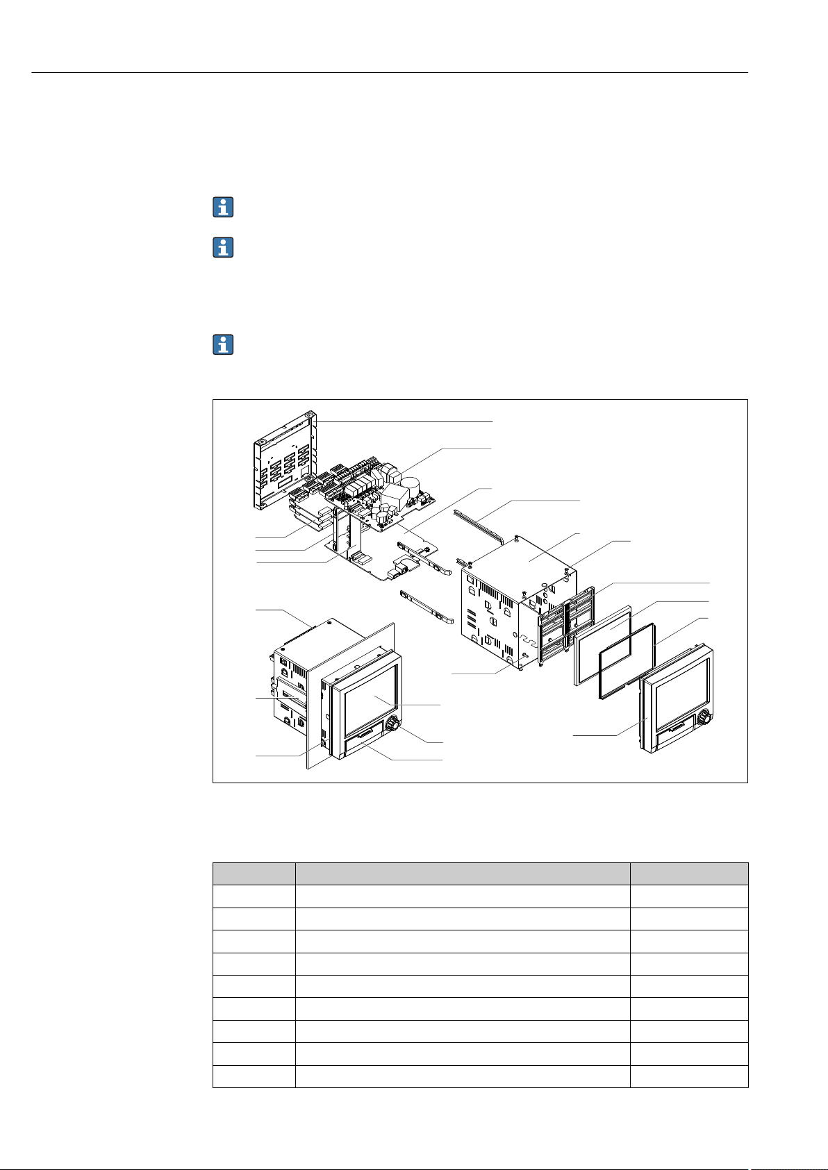
Repairs Ecograph T, RSG35
1
2
3
4
5
6
10
7
8
11
12
13
16
17
18
19
20
14
15
9
13 Repairs
13.1 General notes
Repairs that are not described in these Operating Instructions must only be carried out
directly by the manufacturer or by the service department.
If ordering spare parts, please specify the serial number of the unit! Installation
instructions are included with the spare part.
13.2 Spare parts
Accessories and spare parts currently available for your product can be found online
at: www.endress.com/spareparts_consumables → access to specific device
information → enter serial number.
9 Spare parts diagram
Spare parts list:
Item No. Description Order No.
1 Casing 71155332
12 Jack screw short (1 piece) 71035184
11 Seal housing 71155329
16 Analog card (4 channels) XPR0007-A1
4 Display TFT 5.7" VGA + flat ribbon connector XPR0007-A2
3, 5, 10 Spare parts kit, display XPR0007-A3
6, 7, 8 Front + navigator + flat ribbon connector XPR0007-A4
6, 7, 8 Front neutral + Navigator + flat ribbon connector XPR0007-A5
15, 20 Spare parts kit, card holder XPR0007-A6
58 Endress+Hauser
A0019863
Page 59
Ecograph T, RSG35 Repairs
Item No. Description Order No.
14 Motherboard XPR0007-B1
18 Power supply 24 V AC/DC XPR0007-B2
18 Power supply 100-230 V AC (+/-10%) XPR0007-B3
17 Rear panel analog inputs 71165643
13 Terminals:
Terminal plug-in 3-pole for mains connection "N L PE" RM5.08 –
orange color
Terminal plug-in 3-pole FKC2.5/3-ST-5.08 for relay 1 (changeover) 71037408
Terminal plug-in 4-pole FKC2.5/4-ST-5.08 for relay 2+3 71037410
Terminal plug-in 6-pole FKC2.5/6-ST-5.08 for relay 4+5+6 71037411
Terminal plug-in 9-pole FMC1.5/9-ST-3.5 for digital inputs 71037363
Terminal plug-in 6-pole FMC1.5/6-ST-3.5 for analog input 51009211
71123475
Product structure for CPU with software
Item No. Description Order code
19 CPU + software XPR0008-_ _ _ _
Operating language:
Universal
Software:
Standard
Mathematics
Communication
Ethernet RJ45 + USB
RS232/485 + Ethernet RJ45 + USB
Modbus TCP slave + Ethernet RJ45 + USB
Modbus RTU/TCP slave + RS232/485 + Ethernet RJ45 + USB
Option:
Standard
Neutral
XPR0008-A1
XPR0008-A1A
XPR0008-A1B
XPR0008-A1_ A
XPR0008-A1_ B
XPR0008-A1_ C
XPR0008-A1_ D
XPR0008-A1_ _ A
XPR0008-
Product structure for option retrofit
Item No. Description Order code
Option retrofit (please enter the serial number) XPR0009-_ _
Software:
Standard
Mathematics
Option:
Standard
Neutral
Standard
Modbus TCP slave (Modbus RTU only with RS485)
An RS485 interface is required for Modbus RTU. If there is no
RS485 in the device, a new CPU board must be ordered.
XPR0009-A
XPR0009-B
XPR0009-_ A
XPR0009-_ B
XPR0009-_ _ A
XPR0009-_ _ C
The software option can be enabled directly on the device. After ordering you will
receive instructions and a code that you must enter.
Endress+Hauser 59
Page 60

Repairs Ecograph T, RSG35
13.3 Return
The measuring device must be returned if it is need of repair or a factory calibration, or if
the wrong measuring device has been delivered or ordered. Legal specifications require
Endress+Hauser, as an ISO-certified company, to follow certain procedures when handling
products that are in contact with the medium.
To ensure safe, swift and professional device returns, please refer to the procedure and
conditions for returning devices provided on the Endress+Hauser website at
http://www.endress.com/support/return-material
13.4 Disposal
The device contains electronic components and must therefore be disposed of as electronic
waste. Please pay particular attention to the national disposal regulations in your country.
60 Endress+Hauser
Page 61
Ecograph T, RSG35 Accessories
320 (12.6)
320 (12.6)
254 (10)
14 Accessories
Always quote the serial number of the device when ordering accessories! Installation
instructions are provided with the accessory!
Various accessories, which can be ordered with the device or subsequently from Endress
+Hauser, are available for the device. Detailed information on the order code in question is
available from your local Endress+Hauser sales center or on the product page of the
Endress+Hauser website: www.endress.com.
14.1 Device-specific accessories
Description Order No.
"Industrial Grade" SD card, industry standard, 1GB 71213190
Field Data Manager analysis software with SQL database support (1 x workstation
license, Professional version)
OPC server software (full version on CD) RXO20-11
Description Order No.
Accessories for RXU10 data manager RXU10- _ _
Designation:
Cable set RS232 for connection to PC or modem
USB - RS232 converter
Cable USB-A - USB-B, 1.8 m (5.9 ft)
Configuration software "FieldCare Device Setup" + USB cable
Field housing IP65
MS20-A1
RXU10-B _
RXU10-E _
RXU10-F _
RXU10-G _
RXU10-H _
A0021773
10 Dimensions in mm (in)
Endress+Hauser 61
Page 62
Accessories Ecograph T, RSG35
293.4 (11.55)
236 (9.29)
173 (6.81)
188 (7.4)
184 (7,24)
207.57 (8.17)
Description Order No.
Desktop housing, cable with Schuko plug
Desktop housing, cable with US plug
Desktop housing, cable with Swiss plug
RXU10-I _
RXU10-J _
RXU10-K _
11 Dimensions in mm (in)
Version:
Standard
Neutral
A0021772
RXU10- _ 1
RXU10- _ 2
62 Endress+Hauser
Page 63

Ecograph T, RSG35 Technical data
15 Technical data
15.1 Function and system design
Measuring principle Electronic acquisition, display, recording, analysis, remote transmission and archiving of
analog and digital input signals.
The device is intended for installation in a panel or cabinet. There is also the option of
operating it in a desktop housing or field housing.
Measuring system Multichannel data recording system with multicolored TFT display (145 mm / 5.7" screen
size), galvanically isolated universal inputs (U, I, TC, RTD, pulse, frequency), digital inputs,
transmitter power supply, limit relay, communication interfaces (USB, Ethernet, optional
RS232/485), optionally available with Modbus protocol, 128 MB internal memory,
external SD card and USB stick. An Essential Version of the reporting software is included
for SQL-supported data analysis at the PC.
The number of inputs available in the basic device can be individually increased using
a maximum of 3 plug-in cards. The device supplies power directly to connected twowire transmitters. The device is configured and operated via the navigator (jog/shuttle
dial), via the integrated web server and a PC, or via an external keyboard. Online help
facilitates local operation.
Reliability Dependability
Depending on the device version, the MTBF is between 52 years and 24 years (calculated
based on SN29500 standard at 40°C)
Serviceability
Battery-backed time and data memory. It is advisable to have the backup battery replaced
by a service technician after 10 years.
Real time clock (RTC)
• Configurable summer/normal time changeover
• Battery buffer. It is advisable to have the backup battery replaced by a service technician
after 10 years.
• Drift: <10 min./year
• Time synchronization possible via SNTP or via digital input.
Standard diagnostic functions as per Namur NE 107
The diagnostic code is made up of the error category as per Namur NE 107 and the
message number.
• Cable open circuit, short-circuit
• Incorrect wiring
• Internal device errors
• Overrange/underrange detection
• Ambient temperature out-of-range detection
Device error/alarm relay
One relay can be used as an alarm relay. If the device detects a system error (e.g. hardware
defect) or a malfunction (e.g. cable open circuit), the selected output/relay switches.
This "alarm relay" switches if "F"-type errors occur (F = failure), i.e. "M"-type errors (M=
Maintenance required) do not switch the alarm relay.
Endress+Hauser 63
Page 64

Technical data Ecograph T, RSG35
Safety
The tamper-proof recorded data are saved and can be transferred to an external SQL
database for archiving in a way that prevents subsequent manipulation.
15.2 Input
Measured values Number of analog universal inputs
Standard version without universal inputs. Optional input cards (slot 1-3) with 4 universal
inputs (4/8/12) each.
Number of digital inputs
6 digital inputs
Number of mathematics channels
4 mathematics channels (optional). Mathematics functions can be freely edited via a
formula editor.
Integration of calculated values e.g. for totalization.
Number of limit values
30 limit values (individual channel assignment)
Function of analog universal inputs
You are free to choose between the following measured variables for each universal input:
U, I, RTD, TC, pulse input or frequency input.
Integration of input variable for totalization e.g. flow rate (m3/h) in quantity (m3).
Calculated values
The values of the universal inputs can be used to perform calculations in the mathematics
channels.
Measuring range of analog universal inputs
According to IEC 60873-1: An additional display error of ±1 digit is permitted for every
measured value.
User-definable measuring ranges per universal input of the multifunction card:
Measured
variable
Current (I) 0 to 20 mA; 0 to 20 mA quadratic
Voltage (U)
>1 V
Voltage (U)
≤1 V
Measuring range Maximum measured error of
0 to 5 mA
4 to 20 mA; 4 to 20 mA quadratic
±20 mA
Overrange: up to 22 mA or -22 mA
0 to 10 V; 0 to 10 V quadratic
0 to 5 V
1 to 5 V; 1 to 5 V quadratic
±10 V
±30 V
0 to 1 V; 0 to 1 V quadratic
±1 V
±150 mV
measuring range (oMR),
temperature drift
±0.1% oMR
Temperature drift: ±0.01%/K oMR
±0.1% oMR
Temperature drift: ±0.01%/K oMR
±0.1% oMR
Temperature drift: ±0.01%/K oMR
Input
resistance
Load: 50 Ω
±1 Ω
≥1 MΩ
≥2.5 MΩ
64 Endress+Hauser
Page 65

Ecograph T, RSG35 Technical data
Measured
variable
Resistance
thermometer
(RTD)
Thermocoupl
es (TC)
Pulse input
1)
(I)
Frequency
1)
input (I)
Measuring range Maximum measured error of
measuring range (oMR),
temperature drift
Pt100: -200 to 850 °C (-328 to 1562 °F) (IEC 60751:2008, α=0.00385)
Pt100: -200 to 510 °C (-328 to 950 °F) (JIS C 1604:1984, α=0.003916)
Pt100: -200 to 850 °C (-328 to 1562 °F) (GOST 6651-94, α=0.00391)
Pt500: -200 to 850 °C (-328 to 1562 °F) (IEC 60751:2008, α=0.00385)
Pt500: -200 to 510 °C (-328 to 950 °F) (JIS C 1604:1984, α=0.003916)
Pt1000: -200 to 600 °C (-328 to 1112 °F) (IEC 60751:2008, α=0.00385)
Pt1000: -200 to 510 °C (-328 to 950 °F) (JIS C 1604:1984, α=0.003916)
Cu50: -50 to 200 °C (-58 to 392 °F) (GOST 6651-94, α=4260)
Cu50: -200 to 200 °C (-328 to 392 °F) (GOST 6651-94, α=4280)
Pt50: -200 to 1100 °C (-328 to 2012 °F) (GOST 6651-94, α=0.00391)
Cu100: -200 to 200 °C (-328 to 392 °F) (GOST 6651-94, α=4280)
Pt46: -200 to 1100 °C (-328 to 2012 °F) (GOST 6651-94, α=0.00391)
Cu53: -200 to 200 °C (-328 to 392 °F) (GOST 6651-94, α=4280)
Type J (Fe-CuNi): -210 to 1200 °C (-346 to 2192 °F) (IEC 60584:2013)
Type K (NiCr-Ni): -270 to 1300 °C (-454 to 2372 °F) (IEC 60584:2013)
Type L (NiCr-CuNi): -200 to 800 °C (-328 to 1472 °F) (GOST R8.585:2001)
Type L (Fe-CuNi): -200 to 900 °C (-328 to 1652 °F) (DIN 43710-1985)
Type N (NiCrSi-NiSi): -270 to 1300 °C (-454 to 2372 °F) (IEC 60584:2013)
Type T (Cu-CuNi): -270 to 400 °C (-454 to 752 °F) (IEC 60584:2013)
Type A (W5Re-W20Re): 0 to 2500 °C (32 to 4532 °F) (ASTME 988-96)
Type B (Pt30Rh-Pt6Rh): 42 to 1820 °C (107.6 to 3308 °F) (IEC 60584:2013)
Type C (W5Re-W26Re): 0 to 2315 °C (32 to 4199 °F) (ASTME 988-96)
Type D (W3Re-W25Re): 0 to 2315 °C (32 to 4199 °F) (ASTME 988-96)
Type R (Pt13Rh-Pt): -50 to 1768 °C (-58 to 3214 °F) (IEC 60584:2013)
Type S (Pt10Rh-Pt): -50 to 1768 °C (-58 to 3214 °F) (IEC 60584:2013)
Min. Pulse length 40 μs, max. 12.5 kHz; 0 to 7 mA = LOW; 13 to 20 mA = HIGH Load: 50 Ω
0 to 10 kHz, overrange: up to 12.5 kHz; 0 to 7 mA = LOW; 13 to 20 mA = HIGH ±0.02% @ f <100 Hz of reading
4-wire: ±0.1% oMR
3-wire: ±(0.1% oMR + 0.8 K)
2-wire: ±(0.1% oMR + 1.5 K)
Temperature drift: ±0.01%/K oMR
4-wire: ±0.2% oMR
3-wire: ±(0.2% oMR + 0.8 K)
2-wire: ±(0.2% oMR + 1.5 K)
Temperature drift: ±0.02%/K oMR
4-wire: ±0.3% oMR
3-wire: ±(0.3% oMR + 0.8 K)
2-wire: ±(0.3% oMR + 1.5 K)
Temperature drift: ±0.02%/K oMR
±0.1% oMR from -100 °C (-148 °F)
±0.1% oMR from -130 °C (-202 °F)
±0.1% oMR from -100 °C (-148 °F)
±0.1% oMR from -100 °C (-148 °F)
±0.1% oMR from -100 °C (-148 °F)
±0.1% oMR from -200 °C (-328 °F)
Temperature drift: ±0.01%/K oMR
±0.15% oMR from 500 °C (932 °F)
±0.15% oMR from 600 °C (1112 °F)
±0.15% oMR from 500 °C (932 °F)
±0.15% oMR from 500 °C (932 °F)
±0.15% oMR from 100 °C (212 °F)
±0.15% oMR from 100 °C (212 °F)
Temperature drift: ±0.01%/K oMR
±0.01% @ f ≥100 Hz of reading
Temperature drift: 0.01% of
measured value over the entire
temperature range
Input
resistance
≥1 MΩ
≥1 MΩ
±1 Ω
1) If a universal input is used as a frequency or pulse input, a series resistor must be used in series connection with the voltage source. Example: 1.2
kΩ series resistor at 24 V
Maximum load of inputs
Limit values for input voltage and current as well as cable open circuit detection/line influence/temperature compensation:
Measured variable Limit values (steady-state, without
destroying input)
Current (I) Maximum permitted input voltage: 2.5 V
Maximum permitted input current: 50 mA
Pulse, frequency (I) Maximum permitted input voltage: 2.5 V
Maximum permitted input current: 50 mA
Voltage (U) >1 V Maximum permitted input voltage: 35 V 1 to 5 V range with disengageable cable open circuit monitoring:
Voltage (U) ≤1 V Maximum permitted input voltage: 24 V
Cable open circuit detection/line influence/temperature compensation
4 to 20 mA range with disengageable cable open circuit monitoring to NAMUR
NE43. The following error ranges apply when NE43 is switched on:
≤3.8 mA: underrange
≥20.5 mA: overrange
≤ 3.6 mA or ≥ 21.0 mA: open circuit (display shows: – – – –)
No cable open circuit monitoring
<0.8 V or >5.2 V: cable open circuit (display shows: - - - -)
Endress+Hauser 65
Page 66

Technical data Ecograph T, RSG35
Measured variable Limit values (steady-state, without
destroying input)
Resistance
thermometer (RTD)
Thermocouples (TC) Maximum permitted input voltage: 24 V Influence of line resistance: <0.001%/Ω
Measuring current: ≤1 mA Maximum barrier resistance (or line resistance):
Cable open circuit detection/line influence/temperature compensation
4-wire: max. 200 Ω; 3-wire: max. 40 Ω
Maximum influence of barrier resistance (or line resistance) for Pt100, Pt500
and Pt1000: 4-wire: 2 ppm/Ω, 3-wire: 20 ppm/Ω
Maximum influence of barrier resistance (or line resistance) for Pt46, Pt50,
Cu50, Cu53, Cu100 and Cu500: 4-wire: 6 ppm/Ω, 3-wire: 60 ppm/Ω
Cable open circuit monitoring if any connection is interrupted.
Error, internal temperature compensation: ≤ 2 K
Scan rate
Current/voltage/pulse/frequency input: 100 ms per channel
Thermocouples and resistance temperature detector: 1 s per channel
Data storage/save cycle
Selectable save cycle. Choose from: 1s / 2s / 3s / 4s / 5s / 10s / 15s / 20s / 30s / 1min /
2min / 3min / 4min / 5min / 10min / 15min / 30min / 1h
Typical recording duration
Prerequisites for following tables:
• No limit value violation / integration
• Digital input not used
• Signal analysis 1: off, 2: day, 3: month, 4: year
• No active mathematics channels
Frequent entries in the event log reduce the memory availability!
128 MB internal memory:
Analog inputs Channels in groups Storage cycle (weeks, days, hours)
5 min 1 min 30 s 10 s 1 s
1 1/0/0/0 668, 4, 14 135, 0, 5 67, 4, 4 22, 3, 20 2, 1, 18
4 4/0/0/0 491, 0, 10 99, 4, 17 49, 6, 12 16, 4, 15 1, 4, 16
8 4/4/0/0 246, 1, 14 49, 6, 1 24, 6, 19 8, 2, 7 0, 5, 20
12 4/4/4/0 164, 2, 4 33, 1, 18 16, 4, 13 5, 3, 21 0, 3, 21
External memory, 1 GB SD card:
Analog inputs Channels in groups Storage cycle (weeks, days, hours)
5 min 1 min 30 s 10 s 1 s
1 1/0/0/0 12825, 5, 20 2580, 4, 18 1291, 2, 5 430, 4, 14 43, 0, 12
4 4/0/0/0 8672, 5, 12 1749, 6, 13 875, 6, 13 292, 1, 8 29, 1, 14
8 4/4/0/0 4343, 1, 1 875, 1, 17 438, 0, 6 146, 0, 17 14, 4, 7
12 4/4/4/0 2896, 6, 13 583, 3, 21 292, 0, 6 97, 2, 20 9, 5, 4
The available storage capacity of the internal and external memory can be displayed
in the main menu under "Diagnostics → Device information → Memory
information". The storage capacity depends on the specific device set-up.
66 Endress+Hauser
Page 67

Ecograph T, RSG35 Technical data
Converter resolution
24 bit
Totalization
The interim, daily, monthly and yearly value and the total value can be determined (13digit, 64 bit).
Analysis
Recording of quantity/operating time (standard function), also a min/max/median
analysis within the set time frame.
Digital inputs
Input level To IEC 61131-2: logical “0" (corresponds to -3 to +5 V), activation with logical "1"
(corresponds to +12 to +30 V)
Input frequency max. 25 Hz
Pulse length Min. 20 ms (pulse counter)
Pulse length Min. 100 ms (control input, messages, operating time)
Input current max. 2 mA
Input voltage Max. 30 V
Selectable functions
• Functions of the digital input: control input, ON/OFF message, pulse counter (13-digit,
64 bit), operating time, message+operating time, quantity from time, Modbus slave.
• Functions of the control input: start recording, screen saver on, lock setup, time
synchronization, limit monitoring on/off, lock keyboard/navigator, start/stop analysis.
15.3 Output
Auxiliary voltage output The auxiliary voltage output can be used for loop power supply or to control the digital
inputs. The auxiliary voltage is short-circuit proof and galvanically isolated.
Output voltage 24 VDC ±15%
Output current Max. 250 mA
Galvanic isolation All inputs and outputs are galvanically isolated from each other and designed for the
following testing voltages:
Relay DigitalinAnaloginEthernet RS232/RS485 USB Auxiliary
voltage output
Relay 500
V
Digital in 2 kVDCGalvanic
Analog in 2 kVDC500 VDC500 VDC500 VDC500 V
Ethernet 2 kVDC500 VDC500 VDC- 500 V
RS232/RS485 2 kVDC500 VDC500 VDC500 VDC- 500 V
2 kV
DC
ally
connecte
d
2 kV
DC
500 VDC500 VDC500 V
2 kV
DC
2 kV
DC
DC
DC
DC
DC
2 kV
500 V
500 V
500 V
DC
DC
DC
DC
DC
2 kV
500 V
500 V
500 V
500 V
DC
DC
DC
DC
DC
Endress+Hauser 67
Page 68

Technical data Ecograph T, RSG35
Relay DigitalinAnaloginEthernet RS232/RS485 USB Auxiliary
voltage output
USB 2 kVDC500 VDC500 VDC500 VDC500 V
Auxiliary
voltage output
2 kVDC500 VDC500 VDC500 VDC500 V
DC
DC
Galvanically
connected
500 V
DC
500 V
-
DC
Relay outputs A mix of low voltage (230 V) and safety extra low voltage (SELV circuits) is not permitted
at the connections of the relay contacts.
Alarm relay
1 alarm relay with changeover contact.
Standard relay
5 relays with NO contact, e.g. for limit value messages (can be configured as NC contact).
Relay switching capacity
• Max. switching capacity: 3 A @ 30 V DC
• Max. switching capacity: 3 A @ 250 V AC
• Min. switching load: 300 mW
Switching cycles
5
>10
Cable specification Cable specification, spring terminals
All connections on the rear of the device are designed as pluggable screw or spring
terminal blocks with reverse polarity protection. This makes the connection very quick and
easy. The spring terminals are unlocked with a slotted screwdriver (size 0).
Please note the following when connecting:
• Wire cross-section, auxiliary voltage output, digital I/O and analog I/O: max. 1.5 mm
(14 AWG) (spring terminals)
• Wire cross-section, mains: max. 2.5 mm2 (13 AWG) (screw terminals)
• Wire cross-section, relays: max. 2.5 mm2 (13 AWG) (spring terminals)
• Stripping length: 10 mm (0.39 in)
No ferrules must be used when connecting flexible wires to spring terminals.
Shielding and grounding
Optimum electromagnetic compatibility (EMC) can only be guaranteed if the system
components and, in particular, the lines - both sensor lines and communication lines - are
shielded and the shield forms as complete a cover as possible. A shielded line must be used
for sensor lines that are longer than 30 m. A shield coverage of 90% is ideal. In addition,
make sure not to cross sensor lines and communication lines when routing them. Connect
the shield as often as possible to the reference ground to ensure optimum EMC protection
for the different communication protocols and the connected sensors.
To comply with requirements, three different types of shielding are possible:
• Shielding at both ends
• Shielding at one end on the supply side with capacitance termination at the device
• Shielding at one end on the supply side
2
Experience shows that the best results with regard to EMC are achieved in most cases in
installations with one-sided shielding on the supply side (without capacitance termination
68 Endress+Hauser
Page 69

Ecograph T, RSG35 Technical data
5
6
9
1
Frequency
at the device). Appropriate internal device wiring measures must be taken to allow
unrestricted operation when EMC interference is present. These measures have been
taken into account for this device. Operation in the event of disturbance variables as per
NAMUR NE21 is thus guaranteed.
Where applicable, national installation regulations and guidelines must be observed
during the installation! Where there are large differences in potential between the
individual grounding points, only one point of the shielding is connected directly with the
reference ground.
If the shielding of the cable is grounded at more than one point in systems without
potential matching, mains frequency equalizing currents can occur. These can damage
the signal cable or significantly impact signal transmission. In such cases the shielding
of the signal cable is to be grounded on one side only, i.e. it may not be connected to
the ground terminal of the housing. The shield that is not connected should be
insulated!
15.4 Power supply
Terminal assignment
12 Terminals on back of device
Supply voltage • Extra-low voltage power supply unit ±24 V AC/DC (-10% / +15%) 50/60Hz
• Low voltage power supply unit 100 to 230 V AC (±10%) 50/60Hz
An overload protection element (rated current ≤ 10 A) is required for the power cable.
Power consumption • 100 to 230 V: max. 35 VA
• 24 V: max. 24 VA
The power actually consumed depends on the individual operating state and the device
version (LPS, USB, brightness of screen, number of channels, etc). The active power here is
approx. 3 W to 20 W.
Power supply failure Battery-backed time and data memory. The device starts automatically following a power
failure.
Endress+Hauser 69
A0019304
Page 70

Technical data Ecograph T, RSG35
Electrical connection Details about the electrical connection: → 13
Connector • Panel-mounted device: connected to mains via plug-in screw terminals with reverse
polarity protection
• Desktop version (option): connected to mains via IEC connector
Overvoltage protection To avoid high-energy transients on long signal cables, connect a suitable surge arrester
upstream (e.g. E+H HAW562) in series upstream.
Connection data interface, communication
USB ports (standard):
1 x USB port type A (host)
A USB 2.0 port is available on a shielded USB A socket at the front of the device. A USB
stick, for example, can be connected to this interface as a storage medium. An external
keyboard or USB hub may also be connected.
1 x USB port type B (function)
A USB 2.0 port is available on a shielded USB B socket at the front of the device. This can
be used to connect the device for communication with a laptop, for example.
Ethernet interface (standard):
Ethernet interface on back, 10/100 Base-T, plug type RJ45. The Ethernet interface can be
used to integrate the device via a hub or switch into a PC network (TCP/ IP Ethernet). A
standard patch cable (e.g. CAT5E) can be used for the connection. Using DHCP, the device
can be fully integrated into an existing network without the need for additional
configuration. The device can be accessed from every PC in the network. Normally only the
automatic assignment of the IP address must be configured at the client. When the device
is started, it can automatically retrieve the IP address, subnet mask and gateway from a
DHCP server. If a DHCP is not used, these settings must be made directly in the device
(depends on the network to which the device is to be connected). Two Ethernet function
LEDs are located on the rear of the device.
The following functions are implemented:
• Data communication with PC software (analysis software, configuration software, OPC
server)
• Web server
• WebDAV (Web-based Distributed Authoring and Versioning) is an open standard for
the provisioning of files via the HTTP protocol. The data saved on the device's SD card
can be read out using a PC. A web browser or dedicated WebDAV client can be selected
as network drive on the PC for this purpose.
Serial RS232/RS485 interface (option):
A combined RS232/RS485 connection is available on a shielded SUB D9 socket at the rear
of the device. This can be used for data transfer and to connect a modem. For
communication via modem, we recommend an industrial modem with a watchdog
function.
• The following baud rates are supported: 9600, 19200, 38400, 57600, 115200
• Max. cable length with a shielded cable: 2 m (6.6 ft) (RS232), or 1000 m (3281 ft)
(RS485)
Only one interface can be used at any one time (RS232 or RS485).
70 Endress+Hauser
Page 71

Ecograph T, RSG35 Technical data
15.5 Performance characteristics
Response time
Reference operating conditions
Input Output Time [ms]
Current, voltage, pulse Relay ≤ 550
RTD Relay ≤ 1150
1)
TC
Cable open circuit detection, current input Relay ≤ 1150
Sensor error RTD, TC Relay ≤ 5000
Digital input Relay ≤ 350
1) If internal measuring point temperature compensation is used, otherwise values as for voltage
Reference temperature 25 °C (77 °F) ±5 K
Warm-up period 120 min.
Humidity 20 to 60 % rel. humidity
Hysteresis Can be configured for limit values in the setup
Long-term drift As per IEC 61298-2: max. ±0.1%/year (of measuring range)
Relay ≤ 1550
Mounting location and installation dimensions
15.6 Installation
The device is designed for use in a panel in non-hazardous areas.
Endress+Hauser 71
Page 72

Technical data Ecograph T, RSG35
144 (5.67)
144 (5.67)
141 (5.55)
17 (0.67)
34
(1.34)
X
Y
Field housing assembly and design (optional)
Desktop housing assembly and design (optional)
A0019301
13 Panel mounting and dimensions in mm (in)
Please observe the installation depth of approx. 158 mm (6.22 in) for the device incl.
terminals and fastening clips.
• Panel cutout: 138 to 139 mm (5.43 to 5.47 in) x 138 to 139 mm (5.43 to 5.47 in)
• Panel strength: 2 to 40 mm (0.08 to 1.58 in)
• Angle of vision: from the midpoint axis of the display, 75° to the left and right, 65° above
and below.
• A minimum distance of 15 mm (0.59 in) mm (inch) between the devices must be
observed if aligning the devices in the Y-direction (vertically above one another). A
minimum distance of 10 mm (0.39 in) mm (inch) between the devices must be observed
if aligning the devices in the X-direction (horizontally beside one another).
• Securing to DIN 43 834
As an option, the device can be ordered ready-mounted in a field housing with IP65.
Dimensions (B x H x D) approx.: 320 mm (12.6 in) x 320 mm (12.6 in) x 254 mm (10 in)
As an option, the device can be ordered ready-mounted in a desktop housing.
Dimensions (B x H x D) approx.: 293 mm (11.5 in) x 188 mm (7.4 in) x 211 mm (8.3 in)
(dimensions with bracket, feet and installed device)
72 Endress+Hauser
Page 73

Ecograph T, RSG35 Technical data
15.7 Environment
Ambient temperature
–10 to +50 °C (14 to 122 °F)
range
Storage temperature –20 to +60 °C (–4 to +140 °F)
Humidity 5 to 85 %, not condensating
Climate class To IEC 60654-1: Class B2
Electrical safety Class I equipment, overvoltage category II
Pollution level 2
Altitude < 2 000 m (6 561 ft) above MSL
Degree of protection
Electromagnetic compatibility
Front IP65 / NEMA 4 (not assessed by UL)
Rear IP20
EMC to all relevant requirements of the IEC/EN 61326- series and NAMUR NE21. For
details see declaration of conformity.
• Interference immunity: as per IEC/EN 61326 series (industrial environment) / NAMUR
NE21
Maximum measured error <1% of measuring range
• Interference emissions: as per IEC 61326-1 Class A
15.8 Mechanical construction
Design, dimensions Information about design and dimensions → 71
Weight • Panel-mounted device with maximum configuration: approx. 2.2 kg (4.85 lbs)
• Desktop housing (excluding device): approx. 2.3 kg (5 lbs)
• Field housing (excluding device): approx. 4 kg (8.8 lbs)
Materials
Front frame Zinc die cast GD-Z410, powder-coated
Sight glass Transparent Makrolon plastic (FR clear 099) UL94-V2
Flap; jog/shuttle dial Plastic ABS UL94-V2
Mounting guide rail for PCBs; motherboard fixing unit;
display retainer plate
Seal to panel wall; seal to display; seal in flap; seal to
navigator
Casing; rear panel Galvanized sheet steel St 12 ZE
Plastic PA6-GF15 UL94-V2
Rubber EPDM 70 Shore A
All materials are silicone-free.
Endress+Hauser 73
Page 74

Technical data Ecograph T, RSG35
Materials of desktop housing
• Housing half-panels: sheet steel, electrolytically plated (powder-coated)
• Side sections: aluminum extruded section (powder-coated)
• Section ends: colored polyamide
15.9 Display and operating elements
Operating concept The device can be operated directly onsite, or via remote configuration with the PC via
interfaces and operating tools (Web server, configuration software).
Integrated operating instructions
The device's simple control system enables you to perform commissioning for many
applications without the need for hard copy operating instructions. The device has an
integrated help function and displays operating instructions directly on screen if the
navigator (jog/shuttle dial) is pressed for longer than 3 seconds.
Local operation Display elements
Type
TFT color display
Size (diagonal screen measurement)
145 mm (5.7")
Resolution
VGA 307,200 pixels (640 x 480 pixels)
Backlight
70,000 h half value time (= half brightness)
Number of colors
262,000 viewable colors, 256 colors used
Viewing angle
Viewing angle: 130° vertical, 150° horizontal
Screen display
• Background color white
• Active channels can be assigned to up to 4 groups. These groups can be given a name
e.g. "Temp. boiler 1" or "Daily averages" so that they can be uniquely identified.
• Linear scaling
• Measured value history: quick retrieval of historical data with zoom function
• Preformatted screen displays such as horizontal or vertical curve presentation, bar graph
display or digital display.
74 Endress+Hauser
Page 75
Ecograph T, RSG35 Technical data
6 4
3
2
1
5
7
8
9
10
11
12
Operating elements
A0020602-EN
14 Front of device with open flap
Item
No.
1 "Navigator": jog/shuttle dial for operating with additional press/hold function.
2 LED at SD slot. Orange LED lights up or flashes when the device writes to or reads from the SD card.
3 Slot for SD card
4 USB B socket "Function" e.g. to connect to PC or laptop
5 Green LED lit: power supply present
6 USB A socket "Host" e.g. for USB memory stick or external keyboard
7 In display mode: alternating status display (e.g. set zoom range) of the analog or digital inputs in the
8 In display mode: window for measured value display (e.g. curve display).
9 In display mode: current group name, type of evaluation
10 In display mode: displays current date/time
Operating function (display mode = display of measured values)
(Setup mode = operating in the Setup menu)
In display mode: turn the dial to switch between the various signal groups. Press the dial to display the
main menu.
In setup mode or in a selection menu: turn the dial counterclockwise to move the bar or the cursor
upwards or to the left, changes the parameter. Turning clockwise moves the bar or cursor down or
clockwise, changes parameter.
Do not remove the SD card if the LED is lit or flashing! Risk of data loss!
appropriate color of the channel.
In setup mode: different information can be displayed here depending on the display type.
In setup mode: display of operating menu
In setup mode: name of the current operating item (dialog title)
In setup mode: --
Endress+Hauser 75
Page 76

Technical data Ecograph T, RSG35
Item
No.
11 In display mode: alternating display indicating the percentage space on the SD card or USB stick that
12 In display mode: display of current measured values and the status in the event of an error/alarm
Operating function (display mode = display of measured values)
(Setup mode = operating in the Setup menu)
has already been used.
Status symbols are also displayed in alternation with the memory information.
In setup mode: the current "direct access" operating code is displayed
condition. In the case of counters, the type of counter is displayed as a symbol.
If a measuring point has limit value status, the corresponding channel identifier is highlighted
in red (quick detection of limit value violations). During a limit value violation and device
operation, the acquisition of measured values continues uninterrupted.
Languages The following languages can be selected in the operating menu: German, English, Spanish,
French, Italian, Dutch, Swedish, Polish, Portuguese, Czech, Russian, Japanese, Chinese
(Traditional), Chinese (Simplified)
Remote operation Device access via operating tools
Device configuration and measured value retrieval can also be done via interfaces. The
following operating tools are available for this purpose:
Operating tool Functions Access via
"Field Data Manager
(FDM)" analysis
software, SQL
database support
(included in the
delivery)
Web server
(integrated into the
device; access via
browser)
OPC server
(optional)
"FieldCare/
DeviceCare"
configuration
software (included
in delivery)
• Export of saved data (measured values, analyses, event log)
• Visualization and processing of saved data (measured
values, analyses, event log)
• Safe archiving of exported data in a SQL database
• Display of current and historical data and measured value
curves via the web browser
• Easy configuration without additional installed software
• Remote access to device and diagnostic information
The following instantaneous values can be provided:
• Analog channels
• Digital channels
• Mathematics
• Totalizer
• Device configuration
• Loading and saving device data (upload/download)
• Documentation of the measuring point
RS232/RS485, USB,
Ethernet
Ethernet
RS232/RS485, USB,
Ethernet
USB, Ethernet
System integration The device has (optional) fieldbus interfaces for exporting process values. Measured values
and statuses can also be transmitted to the device via fieldbus. Alarms or errors in the
context of data transmission are displayed depending on the bus system (e.g. status byte).
The process values are transferred in the same devices that are used for display at the
device.
Ethernet
The following functions are implemented:
• Data communication with PC software (analysis software, configuration software, OPC
server)
• Web server
76 Endress+Hauser
Page 77
Ecograph T, RSG35 Technical data
Modbus RTU/TCP slave
The device can be connected to a Modbus system via RS485 or Ethernet interface. Up to 12
analog inputs and 6 digital inputs can be transmitted via Modbus and stored in the device.
15.10 Certificates and approvals
CE mark The measuring system meets the legal requirements of the applicable EC guidelines. These
are listed in the corresponding EC Declaration of Conformity together with the standards
applied. Endress+Hauser confirms successful testing of the device by affixing to it the CE
mark.
UL approval UL recognized component (see www.ul.com/database, search for Keyword "E225237")
CSA The product meets the requirements as per "CLASS 2252 05 - Process Control Equipment"
Other standards and guidelines
• IEC 60529:
Degree of protection provided by housing (IP code)
• IEC/EN 61010-1:
Safety requirements for electrical equipment for measurement, control and laboratory
use
• IEC/EN 61326 Series:
Electromagnetic compatibility (EMC requirements)
15.11 Ordering information
Ordering information Detailed ordering information is available from the following sources:
• In the Product Configurator on the Endress+Hauser website: www.endress.com -> Click
"Corporate" -> Select your country -> Click "Products" -> Select the product using the
filters and search field -> Open product page -> The "Configure" button to the right of the
product image opens the Product Configurator.
• From your Endress+Hauser Sales Center: www.addresses.endress.com
Product Configurator - the tool for individual product configuration
• Up-to-the-minute configuration data
• Depending on the device: Direct input of measuring point-specific information such
as measuring range or operating language
• Automatic verification of exclusion criteria
• Automatic creation of the order code and its breakdown in PDF or Excel output
format
• Ability to order directly in the Endress+Hauser Online Shop
Scope of delivery The scope of delivery of the device comprises:
• Device (with terminals, as per order)
• 2 fastening clips
• USB cable
• Optional: Industrial grade SD card (card is located in the SD slot behind the flap on the
front of the housing)
• "Field Data Manager (FDM)" analysis software on DVD (Essential, Demo or Professional
version, depending on order)
• "FieldCare Device Setup / DeviceCare" configuration software on DVD
• Delivery note
• Multilanguage Brief Operating Instructions, hard copy
Endress+Hauser 77
Page 78
Appendix Ecograph T, RSG35
16 Appendix
16.1 Operating items in the "Expert" menu
The parameter groups for the Expert setup contain all the parameters of the operating
menus: System, Input and Output Setup, Communication, Application, Diagnostics as well
as other parameters that are reserved for experts only.
For most settings, the "Setup" or "Expert" menu must be quit before the settings are
adopted. However settings such as the date/time are accepted immediately.
Direct access
Navigation Expert → Direct access
Description Direct access to active operating items (rapid access). Entering the direct access code takes
you directly to the desired operating parameter. The direct access code is displayed in the
Setup menu on the top right of the display (e.g. 00000-000).
Text entry (e.g. 00000-000)
16.1.1 "System" submenu
Basic settings that are needed to operate the device (e.g. date, time, etc.).
Language
Navigation Expert → System → Language
Direct access code: 010000-000
Description Select unit operating language.
Options German, English, Spanish, French, Italian, Dutch, Polish, Portuguese, Russian, Swedish,
Czech, Japanese, Chinese (Simplified), Chinese (Traditional)
Factory setting English; or preset to customer's preferred language
Device tag
Navigation Expert → System → Device tag
Direct access code: 000031-000
Description Individual device tag.
User entry Text entry (max. 32 characters)
Factory setting Unit 1
78 Endress+Hauser
Page 79

Ecograph T, RSG35 Appendix
Temp. unit
Navigation Expert → System → Temp. unit
Direct access code: 100001-000
Description Selection of temperature unit. All directly connected thermocouples or resistance
thermometers (RTD) are displayed in the preset engineering units.
Options °C, °F, K
Factory setting °C
Decimal separator
Navigation Expert → System → Decimal separator
Direct access code: 100003-000
Description Select in which form the decimal separator character is to be displayed.
Options Comma, point
Factory setting Comma
Fault switching
Navigation Expert → System → Fault switching
Direct access code: 100002-000
Description If the device detects a system error (e.g. hardware defect) or a fault (e.g. cable open
circuit), the selected output switches.
Options Not used, Relay x
All the available relays are displayed
Factory setting Relay 1
Keyboard layout
Navigation Expert → System → Keyboard layout
Direct access code: 100020/000
Description Please select the keyboard layout. Only relevant if external keyboard is used.
Endress+Hauser 79
Page 80

Appendix Ecograph T, RSG35
Options Germany, Switzerland, France, USA, USA International, UK, Italy
Factory setting Germany
Swap mouse buttons
Navigation Expert → System → Swap mouse buttons
Direct access code: 100050/000
Description Swap function of left and right mouse button.
Options No, Yes
Factory setting No
Paper size
Navigation Expert → System → Paper size
Direct access code: 540004/000
Description Please select the paper size of the printer connected to the PC.
Options DIN A4, US Letter
Factory setting DIN A4
Lock operation
Navigation Expert → System → Lock operation
Direct access code: 100060/000
Description Local operation is locked in cases of inactivity once the set time has elapsed to prevent
inadvertent operation (e.g. when cleaning the device). The device is unlocked by pressing
the navigator or the OK operating key for 3 s. When using an external keyboard, the
device is unlocked with the key combination "Ctrl-Alt-Del".
Options Never, After 2 (5, 10, 15) minutes
Factory setting After 5 minutes
PRESET
80 Endress+Hauser
Page 81

Ecograph T, RSG35 Appendix
Navigation Expert → System → PRESET
Direct access code: 000044-000
Description Caution: Resets all the parameters to the factory settings!
Only visible/editable if the service code has been entered.
Options No, Factory reset, Customer setting
Clear memory
Navigation Expert → System → Clear memory
Direct access code: 059000-000
Description Delete internal memory.
Options No, Yes
"Date/time setup" submenu
Navigation Expert → System → Date/time setup
Description Contains settings for date/time.
Date format
Navigation Expert → System → Date/time setup → Date format
Direct access code: 110000-000
Description Select in which format the date is to be set and displayed.
Options DD.MM.YYYY, MM/DD/YYYY, YYYY-MM-DD
Factory setting DD.MM.YYYY
Time format
Navigation Expert → System → Date/time setup → Time format
Direct access code: 110001-000
Description Select in which format the time is to be set and displayed.
Options 24 hour, 12 hour AM/PM
Endress+Hauser 81
Page 82

Appendix Ecograph T, RSG35
Factory setting 24 hour
"Date/time" submenu
Navigation Expert → System → Date/time setup → Date/time
Description Contains parameters for setting the date/time.
UTC time zone
Navigation Expert → System → Date/time setup → Date/time → UTC time zone
Direct access code: 120000-000
Description Display of the current UTC time zone is on (UTC = universal time coordinated).
Current date/time
Navigation Expert → System → Date/time setup → Date/time → Current date/time
Direct access code: 120003-000
Description Displays the current date and the current time.
"Change date/time" submenu
Description Contains parameters for changing the date/time.
Navigation Expert → System → Date/time setup → Change date/time
UTC time zone
Navigation Expert → System → Date/time setup → Date/time → Change date/time → UTC time
zone
Direct access code: 120010-000
Description Set your UTC time zone (UTC = universal time coordinated).
82 Endress+Hauser
Page 83

Ecograph T, RSG35 Appendix
Options -12:00, -11:00: Samoa, -10:00: Hawaii, -09:30: Marquesas, -09:00: Alaska, -08:00: LA,
-07:00: Denver, -06:00: Chicago, -05:00: New York, -04:00: Caracas, -03:30: St.John’s,
-03:00: Brasilia, -02:00: Atlantic, -01:00: Azores, +00:00: London, +01:00: Berlin,
+02:00: Cairo, +03:00: Moscow, +03:30: Tehran, +04:00: Abu Dhabi, +04:30: Kabul,
+05:00: Islamabad, +05:30: New Delhi, +05:45: Kathmandu, +06:00: Dhaka, +06:30:
Pyinmana, +07:00: Bangkok, +08:00: Peking, +08:45, +09:00: Tokyo, +09:30: Adelaide,
+10:00: Canberra, +10:30: Lord-Howe, +11:00:Solom.Isl., +11:30: Norfolk, +12:00:
Auckland, +12:45: Chatham, +13:00, +14:00
Date/time
Navigation Expert → System → Date/time setup → Date/time → Change date/time → Date/time
Direct access code: 120013-000
Description Set the current date and time for the unit here.
User entry Date/time in set format
"NT/ST changeover" submenu
Navigation Expert → System → Date/time setup → NT/ST changeover
Description Contains settings for normal time/summer time changeover.
NT/ST changeover
Navigation Expert → System → Date/time setup → NT/ST changeover → NT/ST changeover
Direct access code: 110002-000
Description Function for summer/normal time changeover.
Automatic: Changeover according to applicable directives for the selected region;
Manual: Set changeover times in the next items;
Off: No time changeover.
Options Off, Manual, Automatic
Factory setting Automatic
NT/ST region
Navigation Expert → System → Date/time setup → NT/ST changeover → NT/ST region
Direct access code: 110003-000
Description Selects the regional settings for summer/normal time changeover.
Only visible if NT/ST changeover = automatic.
Endress+Hauser 83
Page 84

Appendix Ecograph T, RSG35
Options Europe, USA
Factory setting Europe
Begin summer time
Occurrence
Navigation Expert → System → Date/time setup → NT/ST changeover → Occurrence
Direct access code: 110005-000
Description Day, when in the spring a change from normal to summer time occurs.
Visible for NT/ST changeover = Automatic or Manual. Only editable if NT/ST changeover =
Manual.
Options 1st, 2nd, 3rd, 4th, Last
Factory setting Last
Day
Navigation Expert → System → Date/time setup → NT/ST changeover → Day
Direct access code: 110006-000
Description Day, when in the spring a change from normal to summer time occurs.
Visible for NT/ST changeover = Automatic or Manual. Only editable if NT/ST changeover =
Manual.
Options Sunday, Monday, Tuesday, Wednesday, Thursday, Friday, Saturday
Factory setting Sunday
Month
Navigation Expert → System → Date/time setup → NT/ST changeover → Month
Direct access code: 110007-000
Description Month, when in the spring a change from normal to summer time occurs.
Visible for NT/ST changeover = Automatic or Manual. Only editable if NT/ST changeover =
Manual.
Options January, February, March, April, May, June, July, August, September, October, November,
December
84 Endress+Hauser
Page 85

Ecograph T, RSG35 Appendix
Factory setting March
Date
Navigation Expert → System → Date/time setup → NT/ST changeover → Date
Direct access code: 110008-000
Description Date next spring when a change from normal to summer time occurs.
Only visible if NT/ST changeover = Automatic or Manual. Cannot be edited.
Time
Navigation Expert → System →Date/time setup → NT/ST changeover → Time
Direct access code: 110009-000
Description Point of time when the time is moved forward by 1 hour on the day of the changeover
from normal time to summer time (in the set time format).
Visible for NT/ST changeover = Automatic or Manual. Only editable if NT/ST changeover =
Manual.
User entry Time in set time format
Factory setting 02:00
End summer time
Occurrence
Navigation Expert → System → Date/time setup → NT/ST changeover → Occurrence
Direct access code: 110011-000
Description Day, when in the autumn a change from summer to normal time occurs.
Visible for NT/ST changeover = Automatic or Manual. Only editable if NT/ST changeover =
Manual.
Options 1st, 2nd, 3rd, 4th, Last
Factory setting Last
Day
Endress+Hauser 85
Page 86

Appendix Ecograph T, RSG35
Navigation Expert → System → Date/time setup → NT/ST changeover → Day
Direct access code: 110012-000
Description Day, when in the autumn a change from summer to normal time occurs.
Visible for NT/ST changeover = Automatic or Manual. Only editable if NT/ST changeover =
Manual.
Options Sunday, Monday, Tuesday, Wednesday, Thursday, Friday, Saturday
Factory setting Sunday
Month
Navigation Expert → System → Date/time setup → NT/ST changeover → Month
Direct access code: 110013-000
Description Month, when in the autumn a change from summer to normal time occurs.
Visible for NT/ST changeover = Automatic or Manual. Only editable if NT/ST changeover =
Manual.
Options January, February, March, April, May, June, July, August, September, October, November,
December
Factory setting October
Date
Navigation Expert → System → Date/time setup → NT/ST changeover → Date
Direct access code: 110014-000
Description Date next autumn when summer time changes back to normal time.
Only visible if NT/ST changeover = Automatic or Manual. Cannot be edited.
Time
Navigation Expert → System →Date/time setup → NT/ST changeover → Time
Direct access code: 110015-000
Description Point of time when the time is moved back by 1 hour on the day of the changeover from
summer time to normal time (in the set time format).
Visible for NT/ST changeover = Automatic or Manual. Only editable if NT/ST changeover =
Manual.
User entry Time in set time format
Factory setting 02:00
86 Endress+Hauser
Page 87

Ecograph T, RSG35 Appendix
"SNTP" submenu
Navigation Expert → System → Date/time setup → SNTP
Description Contains settings for time synchronization using the Simple Network Time Protocol
(SNTP).
SNTP
Navigation Expert → System → Date/time setup → SNTP
Direct access code: 110020-000
Description If switched on, time synchronization is carried out via SNTP once a day.
Note: Only possible via Ethernet.
Port 123 must be open in the firewall. The user/network administrator is responsible for
the accuracy of the time server.
Options No, Yes
Factory setting No
SNTP server 1
Navigation Expert → System → Date/time setup → SNTP server → SNTP server 1
Direct access code: 110021-000
Description Please specify the address of the time server (or the IP address).
Note: The DNS server must be configured (see Communication/Ethernet).
Your administrator can provide the address where necessary.
User entry Text field
SNTP server 2
Navigation Expert → System → Date/time setup → SNTP Server → SNTP server 2
Direct access code: 110025-000
Description Shows the IP address of the time server if it was automatically allocated via DHCP. Non-
editable display text.
An attempt is always made to synchronize the time via SNTP server 1 first (provided
it is configured).
DHCP must be switched on (see Communication/Ethernet).
DHCP server: Option 42.
Endress+Hauser 87
Page 88

Appendix Ecograph T, RSG35
"Security" submenu
Navigation Expert → System → Security
Description Contains settings that protect the unit against unauthorized operation and configuration.
Protected by
Navigation Expert → System → Security → Protected by
Direct access code: 100006-000
Description Configure how the device should be protected.
Options Open access, access code, user roles
Factory setting Open access
Access code
Navigation Expert → System → Security → Access code
Direct access code: 100000-000
Description Using this code, setup access can be protected from unauthorized persons. In order to
change any parameter the correct code must be entered. Factory setting: "0", i.e. changes
can be made at any time.
Hint: Make a note of the code and store in a safe place.
Only visible if "Protected by" = "Access code".
User entry 4-digit number
Factory setting 0
Set point code
Navigation Expert → System → Security → Set point code
Direct access code: 100030-000
Description If the unit is protected by an access code a set point code can also be defined. The user can
change the set points once the set point code is entered. All other operating positions
remain locked, however.
Only visible if an access code has been defined.
Factory default: "0" means that alarm set points can only be changed by entering the access
code.
Alarm set point code and access code should not be identical!
88 Endress+Hauser
Page 89

Ecograph T, RSG35 Appendix
User entry 4-digit number
Factory setting 0
Lock hardware
Navigation Expert → System → Security → Lock hardware
Direct access code: 100099-000
Description Device functions/interfaces that are not used can be switched off for security reasons.
Fieldbuses may also be affected in the case of Ethernet or the serial interface.
Please follow the operating instructions.
Options Ethernet (all ports/services), USB A socket front, USB A socket back, USB B socket front,
Serial interface, SD card
Factory setting No lock
"Authentication" submenu
Navigation Expert → System → Security → Authentication
Description Define the passwords for the various user roles to allow device access.
Visible only if "Protected by" = "User roles".
Operator
ID: operator
Password
Navigation Expert → System → Security → Authentication → Password
Direct access code: 470105/000
Description Enter a password for this user account.
Options Text entry max. 12 characters
Factory setting operator
Administrator
ID: admin
Password
Endress+Hauser 89
Page 90
Appendix Ecograph T, RSG35
Navigation Expert → System → Security → Authentication → Password
Direct access code: 470102/000
Description Enter a password for this user account.
Options Text entry max. 12 characters
Factory setting admin
Service
ID: service
Password
Navigation Expert → System → Security → Authentication → Password
Direct access code: 470101/000
Description Enter a password for this user account.
Options Text entry max. 12 characters
Factory setting service
"External memory" submenu
Navigation Expert → System → External memory
Description Contains settings for the external data carrier, amongst other things which data are to be
stored in which format on the external data carrier.
Save as
Navigation Expert → System → External memory → Save as
Direct access code: 140000-000
Description "Protected format": All data are stored in a manipulation protected encrypted format. They
can be interpreted only by the PC analysis software provided.
"Open format": data are stored in a CSV format, this can be opened by a number of different
programs (e.g. MS Excel) (Attention: no manipulation security).
Options Protected format, Open format (*.csv)
Factory setting Protected format
SD card
90 Endress+Hauser
Page 91
Ecograph T, RSG35 Appendix
Memory build-up
Navigation Expert → System → External memory → Memory build-up
Direct access code: 140001-000
Description "Stack memory": no more data can be stored once the data carrier is full.
"Ring memory": once the data carrier is full the oldest data are deleted so that new data can
be stored (First in first out (FIFO).
The "Ring memory" setting refers only to the automatic storage of measured values.
Manual save functions ("Operation -> SD card -> Update/Save measured values") are
not affected.
Options Stack memory, Ring memory (FIFO)
"Ring memory" can be selected only if "Save as" is set to "protected format" (and not
"CSV").
Factory setting Stack memory
Warning at
Navigation Expert → System → External memory → Warning at
Direct access code: 140005-000
Description Issues a warning before the data carrier is x% full.
A warning is indicated on the device and this is also stored in the event buffer.
A relay can also be switched.
Only for external SD card (does not apply to USB stick)!
User entry 0 to 99%
Factory setting 90
Switches relay
Navigation Expert → System → External memory → Switches relay
Direct access code: 140006-000
Description When the warning "Data carrier full" is displayed a relay can also be switched on.
Options Not used, Relay x
All the available relays are displayed
Factory setting Not used
Endress+Hauser 91
Page 92

Appendix Ecograph T, RSG35
CSV settings
Also configurable if "Protected format" is set.
Separator for CSV
Navigation Expert → System → External memory → Separator for CSV
Direct access code: 140002-000
Description Configure which separator is used by your application (e.g. in Excel = semicolon).
Options Comma, Semicolon
Factory setting Semicolon
Date/time
Navigation Expert → System → External memory → Date/time
Direct access code: 140003-000
Description Please select if the date and time should be stored in one column or separate columns
when data are saved in CSV format files.
Options One column, Separate columns
Factory setting Separate columns
Operating time
Navigation Expert → System → External memory → Operating time
Direct access code: 140004-000
Description Please select in which format operation times will be stored/displayed.
Options 0 seconds, 0.0000 hours, 0.00000 days, 0000h00:00
Factory setting 0000h00:00
"Messages" submenu
Navigation Expert → System → Messages
92 Endress+Hauser
Page 93

Ecograph T, RSG35 Appendix
Description Contains settings for displaying/acknowledging messages. Examples of messages include:
messages triggered by set-points; messages triggered by a digital input; error messages;
etc.
Acknowledging messages
Navigation Expert → System → Messages → Acknowledging messages
Direct access code: 100040-000
Description The time the message is acknowledged can be saved in the events list.
Options Do not save, Save
Factory setting Do not save
Switches relay
Navigation Expert → System → Messages → Switches relay
Direct access code: 100042-000
Description A relay can be switched as soon as a message that has to be confirmed is displayed (e.g.
on/off message, device errors etc.).
The relay assumes the initial status as soon as all messages have been confirmed.
Options Not used, Relay x
All the available relays are displayed
Factory setting Not used
"Screen saver" submenu
Navigation Expert → System → Screensaver
Description To increase the life span of the LCDs the backlight can be switched off (= screen saver).
Screen saver
Navigation Expert → System → Screen saver → Screen saver
Direct access code: 160000-000
Description "Switched off": LCD is always switched on.
“Switch on for x min.”: display goes dark after x minutes. All other functions remain in
operation. Press an operating key: Illumination is switched back on.
"Switch daily": Enter time span.
Endress+Hauser 93
Page 94
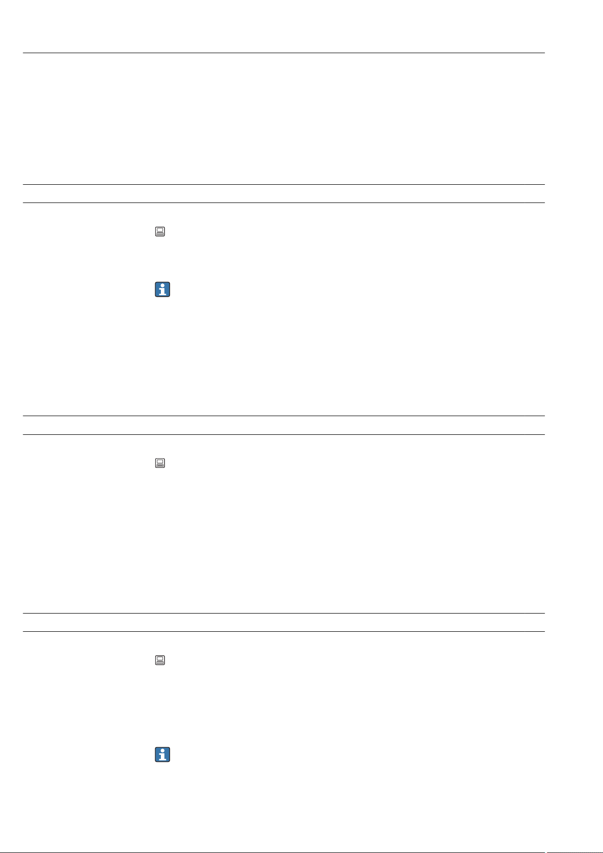
Appendix Ecograph T, RSG35
Options Switched off, On after 10 min, On after 30 min, On after 60 min, Switched daily, Control
input
Factory setting Switched off
This setting has no effect if the screen saver is controlled by a digital input→ 115
ON daily from
Navigation Expert → System → Screen saver → ON daily from
Direct access code: 160001-000
Description Set time (hh:mm) as of when the screensaver should be switched on (e.g. shift end time).
The screen saver is switched off as soon as the device is operated via onsite
operation. After 1 min of inactivity it switches back on automatically.
Only visible if screen saver = switched daily
User entry Time (hh:mm)
Factory setting 20:00
OFF daily from
Navigation Expert → System → Screen saver → OFF daily from
Direct access code: 160002-000
Description Set time (hh:mm) as of when the screensaver should be switched off (e.g. shift start time).
Only visible if screen saver = switched daily.
User entry Time (hh:mm)
Factory setting 07:00
Alarm response
Navigation Expert → System → Screen saver → Alarm response
Direct access code: 160003-000
Description "Off on alarm": If limit value violations occur or status signal "Maintenance required (Mxxx)"
or "Check function (Cxxx)" is active, the screensaver will be automatically deactivated.
"Always on": If limit value violations occur or status signal "Maintenance required (Mxxx)"
or "Check function (Cxxx)" is active, the screensaver will not be deactivated.
Active messages that require acknowledgment or an active status signal "Failure
(Fxxx)" or "Out of specification (Sxxx)" deactivate the screensaver always.
Options Off on alarm, Always on
94 Endress+Hauser
Page 95
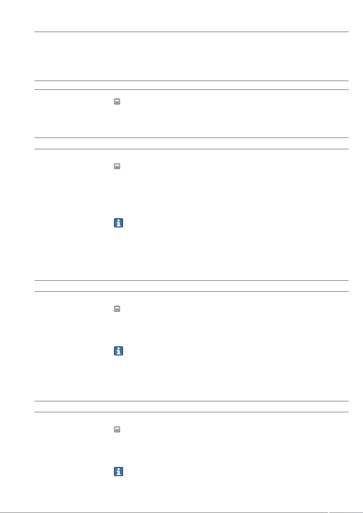
Ecograph T, RSG35 Appendix
Factory setting Off on alarm
"Device options" submenu
Navigation Expert → System → Device options
Description Hardware and software options of the device.
Activation code
Navigation Expert → System → Device options → Activation code
Direct access code: 000057-000
Description Here, you can enter a code to enable the device options.
Options that can be upgraded can be found under "Spare parts" → 59.
Note: When an activation code is entered, the device is restarted in order to enable the
new option.
• The activation code entered is not displayed, i.e. this parameter is always empty
following a restart.
• Pay attention to case-sensitivity.
User entry Text
Slot 1
Navigation Expert → System → Device options → Slot 1
Direct access code: 990000-000
Description Shows hardware or software options.
Cannot be edited.
The assignment can be specified in the PC operating software for offline
configuration.
Options Not assigned, Universal inputs
Slot 2
Navigation Expert → System → Device options → Slot 2
Direct access code: 990001-000
Description Shows hardware or software options.
Cannot be edited.
The assignment can be specified in the PC operating software for offline
configuration.
Endress+Hauser 95
Page 96

Appendix Ecograph T, RSG35
Options Not assigned, Universal inputs
Slot 3
Navigation Expert → System → Device options → Slot 3
Direct access code: 990002-000
Description Shows hardware or software options.
Cannot be edited.
The assignment can be specified in the PC operating software for offline
configuration.
Options Not assigned, Universal inputs
Communication
Navigation Expert → System → Device options → Communication
Direct access code: 990006-000
Description Shows hardware or software options.
Cannot be edited.
Options USB + Ethernet, USB + Ethernet + RS232/485
Fieldbus
Navigation Expert → System → Device options → Fieldbus
Direct access code: 990005-000
Description Shows hardware or software options.
Cannot be edited.
Options Not available, Modbus Slave
Application
Navigation Expert → System → Device options → Application
Direct access code: 990007-000
Description Shows hardware or software options.
Cannot be edited.
96 Endress+Hauser
Page 97

Ecograph T, RSG35 Appendix
Options Standard, Maths
16.1.2 "Inputs" submenu
Settings for analog and digital inputs.
"Universal inputs" submenu
Navigation Expert → System → Inputs → Universal inputs
Description Settings for the connected measuring points.
Add input
Navigation Expert → System → Inputs → Universal inputs → Add input
Direct access code: 222000/000
Description Addition of an input that must be switched on and configured according to the input
signal.
Options No, universal input x
Factory setting No
Delete input
Navigation Expert → System → Inputs → Universal inputs → Delete input
Direct access code: 222001/000
Description Delete an input configuration.
Options No, universal input x
Factory setting No
"Universal input x" submenu
Navigation Expert → System → Inputs → Universal inputs→ Universal input x
Description View or change settings for the selected channel.
x = place holder for selected universal input.
Signal
Endress+Hauser 97
Page 98

Appendix Ecograph T, RSG35
Navigation Expert → Inputs → Universal inputs → Universal input x → Signal
Direct access code: 220000-0xx
Examples: Universal input 1: 220000-000; Universal input 12: 220000-011
Description Select the type of signal connected (current, voltage, etc.). The channel is switched off if no
signal type is selected (factory default).
Options Switched off, Current, Voltage, Resistance temperature detector, Thermocouple, Pulse
counter, Frequency input, Modbus Slave (option)
Factory setting Switched off
Range
Navigation Expert → Inputs → Universal inputs → Universal input x → Range
Direct access code: 220001-0xx
Examples: Universal input 1: 220001-000; Universal input 12: 220001-011
Description Select the input range or which resistance thermometer/thermocouple is connected. The
respective terminal layout can be found in the Operating Instructions or on the rear of the
unit.
Only visible if signal ≠ switched off.
Options Switched off
Current: 4-20 mA, 0-20 mA, 0-5 mA, 0-20 mA squared, 4-20 mA squared, ±20 mA
Voltage: 0-1 V, 0-10 V, 0-5 V, 1-5 V, ±150 mV, ±1 V, ±10 V, ±30 V, 0-1 V squared, 0-10
V squared, 1-5 V squared
Resistance thermometer: Pt100 (IEC), Pt100 (JIS), Pt100 (GOST), Pt500 (IEC), Pt500 (JIS),
Pt1000 (IEC), Pt1000 (JIS), Pt46 (GOST), Pt50 (GOST), Cu50 (GOST, a=4260), Cu50
(GOST, a=4280), Cu53 (GOST, a=4280), Cu100 (GOST, a=4280)
Thermocouple: Type A (W5Re-W20Re), type B (Pt30Rh-Pt6Rh), type C (W5Re-W26Re),
type D (W3Re-W25Re), type J (Fe-CuNi), type K (NiCr-Ni), type L (Fe-CuNi), type L (NiCrCuNi, GOST), type N (NiCrSi-NiSi), type R (Pt13Rh-Pt), type S (Pt10Rh-Pt), type T (CuCuNi)
Pulse counter
Frequency input
Modbus (option)
Factory setting Switched off
Connection
Navigation Expert → Inputs → Universal inputs → Universal input x → Connection
Direct access code: 220002-0xx
Examples: Universal input 1: 220002-000; Universal input 12: 220002-011
Description Specify whether RTDs are connected as 2-, 3- or 4-wire systems.
Only visible if signal = resistance thermometer.
Options 2-wire, 3-wire, 4-wire
98 Endress+Hauser
Page 99

Ecograph T, RSG35 Appendix
Factory setting 4-wire
Channel ident.
Navigation Expert → Inputs → Universal inputs → Universal input x → Channel ident.
Direct access code: 220003-0xx
Examples: Universal input 1: 220003-000; Universal input 12: 220003-011
Description Name of the measuring point connected to this input.
Only visible if signal ≠ switched off.
User entry Text (16 characters)
Factory setting Channel x
Plot type
Navigation Expert → Inputs → Universal inputs → Universal input x → Plot type
Direct access code: 220016-0xx
Examples: Universal input 1: 220016-000; Universal input 12: 220016-011
Description The analog inputs are scanned in a 100ms cycle. Depending on the memory cycle, the
selected data are determined, saved, and displayed based on the scanned values.
Options Instantaneous value, Average, Minimum value, Maximum value, Minimum + Maximum,
Counter, Current value + Counter
Factory setting Average
Time base
Navigation Expert → Inputs → Universal inputs → Universal input x → Time base
Direct access code: 220025-0xx
Examples: Universal input 1: 220025-000; Universal input 12: 220025-011
Description A current value can be determined from the counter reading with the aid of the time base
e.g. input liters, time base = second → current value = liters/second.
Only visible if signal = "Pulse counter" and plot type = "Current value + counter".
Options Second (s), Minute (min), Hour (h), Day (d)
Factory setting Second (s)
Endress+Hauser 99
Page 100

Appendix Ecograph T, RSG35
Engineering unit
Navigation Expert → Inputs → Universal inputs → Universal input x → Engineering unit
Direct access code: 220004-0xx
Examples: Universal input 1: 220004-000; Universal input 12: 220004-011
Description Specify the technical (physical) unit for the measuring point connected to this input.
Only visible if signal ≠ switched off.
User entry Text (6 characters)
Unit/dimension counter
Navigation Expert → Inputs → Universal inputs → Universal input x → Unit/dimension counter
Direct access code: 220024-00x
Examples: Universal input 1: 220024-000; Universal input 12: 220024-011
Description Technical units of the count input, e.g. gal, cf.
Only visible if signal = "Pulse counter" and plot type = "Current value + counter".
User entry Text (max. 6 characters)
Pulse counter
Navigation Expert → Inputs → Universal inputs → Universal input x → Pulse counter
Direct access code: 220017-0xx
Examples: Universal input 1: 220017-000; Universal input 12: 220017-011
Description Please check if the pulse counter used is a fast or slow (up to a max. 25 Hz) counter. For
example if the number of state changes from a relay are to be monitored then you must
set up "up to 25Hz".
Only visible if signal = pulse counter.
Options Up to 13kHz, Up to 25Hz
Factory setting Up to 13kHz
Pulse value
Navigation Expert → Inputs → Universal inputs → Universal input x → Pulse value
Direct access code: 220010-0xx
Examples: Universal input 1: 220010-000; Universal input 12: 220010-011
100 Endress+Hauser
 Loading...