


 Loading...


 Monitoring


 For Business-Critical Continuity™


 Liebert ®SiteLink-E™


 Installation Manual - Liebert SiteLink-2E, Liebert SiteLink-4E and Liebert SiteLink-12E


TABLE OF CONTENTS
1.0 PRODUCT OVERVIEW . . . . . . . . . . . . . . . . . . . . . . . . . . . . . . . . . . . . . . . . . . . . . . . . . . . . .1 2.0 INSTALLING THE LIEBERT SITELINK-E MODULE . . . . . . . . . . . . . . . . . . . . . . . . . . . . . . . . . .2
2.1 Preparations for Mounting the Module. . . . . . . . . . . . . . . . . . . . . . . . . . . . . . . . . . . . . . . . . . . 2
2.1.1 Choose a Location to Install the Liebert SiteLink-E . . . . . . . . . . . . . . . . . . . . . . . . . . . . . . . . . 2
2.2 Enclosure Diagrams . . . . . . . . . . . . . . . . . . . . . . . . . . . . . . . . . . . . . . . . . . . . . . . . . . . . . . . . . . 2
3.0 CONNECT INPUT POWER WIRING . . . . . . . . . . . . . . . . . . . . . . . . . . . . . . . . . . . . . . . . . . . .5
3.1 Power Wiring . . . . . . . . . . . . . . . . . . . . . . . . . . . . . . . . . . . . . . . . . . . . . . . . . . . . . . . . . . . . . . . 5
3.1.1 Input Power Requirements . . . . . . . . . . . . . . . . . . . . . . . . . . . . . . . . . . . . . . . . . . . . . . . . . . . . . 5
3.2 Connect Input Power—AC or DC . . . . . . . . . . . . . . . . . . . . . . . . . . . . . . . . . . . . . . . . . . . . . . . 6
4.0 COMMUNICATION AND CONTROL WIRING. . . . . . . . . . . . . . . . . . . . . . . . . . . . . . . . . . . . . . .7
4.1 IGM Communication . . . . . . . . . . . . . . . . . . . . . . . . . . . . . . . . . . . . . . . . . . . . . . . . . . . . . . . . . 7
4.1.1 Wiring IGM Ports . . . . . . . . . . . . . . . . . . . . . . . . . . . . . . . . . . . . . . . . . . . . . . . . . . . . . . . . . . . . . 8
4.2 RS-485 and ARC156 Wiring Considerations . . . . . . . . . . . . . . . . . . . . . . . . . . . . . . . . . . . . . . 9 4.3 Wiring for BACnet/ARC156 Network . . . . . . . . . . . . . . . . . . . . . . . . . . . . . . . . . . . . . . . . . . . . 9 4.4 Wiring Port S1 . . . . . . . . . . . . . . . . . . . . . . . . . . . . . . . . . . . . . . . . . . . . . . . . . . . . . . . . . . . . . 10
4.4.1 Wiring Port S1 for RS-485 Network—Four-Wire . . . . . . . . . . . . . . . . . . . . . . . . . . . . . . . . . . . 10 4.4.2 Wiring Port S1 for RS-485—Two-Wire . . . . . . . . . . . . . . . . . . . . . . . . . . . . . . . . . . . . . . . . . . . 11 4.4.3 Wiring Port S1 for RS-232 . . . . . . . . . . . . . . . . . . . . . . . . . . . . . . . . . . . . . . . . . . . . . . . . . . . . . 12
4.5 Wiring a Modem for Half-Router Communication—Port S1 . . . . . . . . . . . . . . . . . . . . . . . . . 12
5.0 SPECIFICATIONS . . . . . . . . . . . . . . . . . . . . . . . . . . . . . . . . . . . . . . . . . . . . . . . . . . . . . . . .13
APPENDIX A - COMMUNICATION PROTOCOL AND WIRING CONSIDERATIONS . . . . . . . . . . . . . . . . .15
A.1 Differences Between RS-485 and RS-422 . . . . . . . . . . . . . . . . . . . . . . . . . . . . . . . . . . . . . . . . 15
A.2 Termination . . . . . . . . . . . . . . . . . . . . . . . . . . . . . . . . . . . . . . . . . . . . . . . . . . . . . . . . . . . . . . . 15
A.3 Bias . . . . . . . . . . . . . . . . . . . . . . . . . . . . . . . . . . . . . . . . . . . . . . . . . . . . . . . . . . . . . . . . . . . . . . 16
i

FIGURES
Figure 1 Liebert SiteLink-E layout—power and communication connections, ports and switches . . . . . . . 1 Figure 2 Module dimensions, without enclosure . . . . . . . . . . . . . . . . . . . . . . . . . . . . . . . . . . . . . . . . . . . . . . . 2 Figure 3 Enclosure dimensions—overall . . . . . . . . . . . . . . . . . . . . . . . . . . . . . . . . . . . . . . . . . . . . . . . . . . . . . 3 Figure 4 Enclosure dimensions—Wall mount . . . . . . . . . . . . . . . . . . . . . . . . . . . . . . . . . . . . . . . . . . . . . . . . . 3 Figure 5 Enclosure dimensions—Floor mount . . . . . . . . . . . . . . . . . . . . . . . . . . . . . . . . . . . . . . . . . . . . . . . . . 4 Figure 6 Power connections. . . . . . . . . . . . . . . . . . . . . . . . . . . . . . . . . . . . . . . . . . . . . . . . . . . . . . . . . . . . . . . . 6 Figure 7 IGM connections . . . . . . . . . . . . . . . . . . . . . . . . . . . . . . . . . . . . . . . . . . . . . . . . . . . . . . . . . . . . . . . . . 8 Figure 8 Liebert precision cooling units networked with Liebert SiteLink-E modules . . . . . . . . . . . . . . . . . 8 Figure 9 BACnet/ARC156 Network port . . . . . . . . . . . . . . . . . . . . . . . . . . . . . . . . . . . . . . . . . . . . . . . . . . . . . 9 Figure 10 Liebert SiteLink-E modules in ARCnet network . . . . . . . . . . . . . . . . . . . . . . . . . . . . . . . . . . . . . . 10 Figure 11 Port S1 jumpers and DIP switches . . . . . . . . . . . . . . . . . . . . . . . . . . . . . . . . . . . . . . . . . . . . . . . . . 11 Figure 12 RS-232 connection to Port S1 . . . . . . . . . . . . . . . . . . . . . . . . . . . . . . . . . . . . . . . . . . . . . . . . . . . . . . 12 Figure 13 Fabricated cable for modem in half-router communication . . . . . . . . . . . . . . . . . . . . . . . . . . . . . . 12
TABLES
Table 1 Specifications. . . . . . . . . . . . . . . . . . . . . . . . . . . . . . . . . . . . . . . . . . . . . . . . . . . . . . . . . . . . . . . . . . . 13 Table 2 Communication ports, protocols and settings . . . . . . . . . . . . . . . . . . . . . . . . . . . . . . . . . . . . . . . . . 14
ii

Product Overview
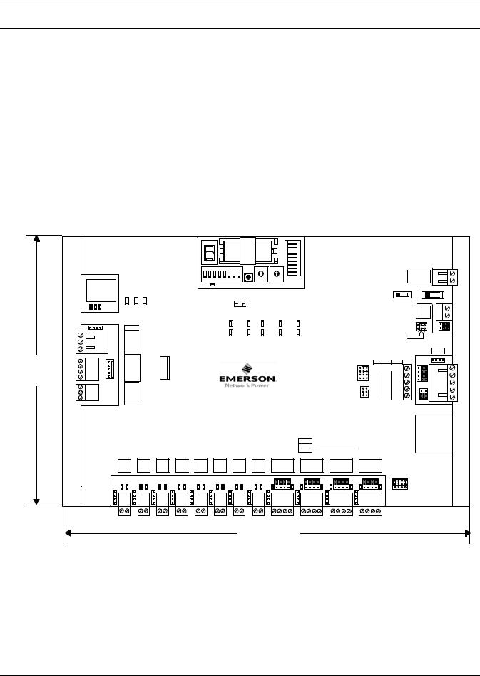
1.0PRODUCT OVERVIEW
The Liebert SiteLink-E® interface module is a BACnet router that provides the communications link between Liebert units and other protocols and modules. The Liebert SiteLink-E module communicates with Liebert equipment such as environmental units, UPSs, frequency converters and power distribution units.
See Figure 1 for port locations.
Figure 1 Liebert SiteLink-E layout—power and communication connections, ports and switches
All features, including ports available in same configuration on all models, except where noted
Module Status |
|
|
Format Button |
|
|
|
Address |
|||||||||||
Indicator |
|
Battery |
|
|
|
|
|
|
|
|
|
|
|
Switches |
||||
DIP Switches |
|
|
|
|
|
|
|
|
|
|
|
|
||||||
|
|
|
|
|
|
|
|
|
|
|
|
|
|
|
|
|||
|
|
|
|
|
|
|
|
|
|
|
|
|
|
|
|
|
|
|
DIP |
SL12E |
|
Module |
|
|
|
|
|
|
|
|
|
|
|
|
|
|
ARCnet transmit |
|
Status |
|
|
|
|
|
|
|
|
|
|
|
|
|
|
ARCnet receive |
||
Switch |
|
|
|
|
|
|
|
|
|
|
|
|
|
|
|
|
Archive Valid |
|
|
|
Chase = OK |
|
|
|
|
|
|
|
|
|
|
|
|
|
|
||
|
|
|
Error Codes: |
|
|
|
|
|
|
|
|
|
|
|
|
|
|
|
Key |
|
|
0 = Download required |
|
|
|
|
|
|
|
|
|
|
|
|
|
|
Port S1 transmit |
|
|
1 |
2 |
3 |
4 |
5 |
6 |
7 |
8 |
|
0 |
|
|
0 |
|
Port S1 receive |
||
|
|
1 = Control Program Error |
89 |
12 |
8 9 |
12 |
|
|||||||||||
|
|
|
|
|
|
|
|
|
|
|
|
Battery low |
||||||
|
10/100 |
BaseT |
2 = RAM full |
|
|
|
|
|
|
|
|
7 |
5 |
3 |
7 |
5 |
3 |
|
|
3 = Comm setup error |
|
|
|
|
|
|
|
|
6 |
4 |
6 |
4 |
|
||||
Ethernet |
Ethernet Port |
4 = System error |
|
LED |
|
|
|
CR-123A |
|
|
|
|
|
|
|
|||
|
|
8 = Formatting |
|
|
|
|
|
|
|
|
|
|
|
|||||
|
|
|
Blinking Dot= “Run” |
|
Power |
3V Lithium Battery |
10's |
|
|
1's |
|
|||||||
Port |
|
|
|
|
|
|
|
|
|
|
|
|
|
Module |
|
|||
100 LAN LINK |
|
|
|
|
|
|
|
|
|
|
|
Address |
|
|||||
|
|
|
|
|
|
|
|
|
|
|
|
|
||||||
|
OverBACnetARCNET156 KBaud |
|
|
|
|
|
Sw |
1 |
|
2 |
|
3 |
|
|
4 |
5 |
||
|
|
® |
|
|
|
|
|
|
|
|
|
|||||||
|
|
|
|
|
|
|
|
On |
|
|
Assigned +100 |
|
|
Enable |
Enable |
|||
|
BT485 |
|
|
|
|
|
|
|
|
|
|
|
|
|
|
|
|
|
ARCnet 156 Port |
Net + |
|
|
|
|
|
|
Off |
|
|
Default |
0 |
|
|
Disable |
Disable |
||
Port |
|
|
|
|
|
|
|
|
|
|
|
|
|
|
|
|
||
|
Net - |
ARCnet |
|
|
|
|
Enhanced Access IP Addr |
Address |
|
MSTP |
PTP |
|||||||
|
|
|
|
|
|
|
on Rnet |
|
|
|
|
|
on S1 |
on S1 |
||||
|
Shield |
|
|
|
|
|
|
|
|
|
|
|
|
|
|
|
|
|
|
Gnd |
|
|
|
|
|
|
|
|
|
|
|
|
|
|
|
|
|
|
Rnet + |
Rnet |
Local |
|
|
|
|
|
|
|
|
|
|
|
|
|
|
|
|
Rnet - |
Access |
|
|
|
|
|
|
|
|
|
|
|
|
|
|
|
|
|
+12V |
|
|
|
|
|
|
|
|
|
|
|
|
|
|
|
|
|
|
Xnet + |
Xnet |
|
|
|
|
SiteLink-E |
|
||||||||||
|
Gnd |
Remote |
|
|
|
|
||||||||||||
|
Xnet - |
|
|
|
|
|
|
|
|
|
|
|
|
|
|
|
||
|
|
Expansion |
|
|
|
|
|
|
|
|
|
|
|
|
|
|
|
|
SSW-12E
Communication
Status LEDs
|
|
24Vac, 24VA, 1A, 50-60 Hz |
|
|
|
|
|
26Vdc, 10W, 0.4A |
|
Ground and |
|
|
|
Use Copper Conductors Only |
|
||
|
|
Class 2 |
|
|
|
|
|
|
Ground |
24VAC Terminals |
|
|
|
|
24ac/26dc |
|
|
|
|
|
Power |
|
Power Switch |
|
|
|
On Off |
|
|
|
|
|
Battery |
+3V |
External Battery |
|
|
|
External |
Gnd |
|
|
|
|
Ext. Batt . |
|
Connection |
|
|
|
|
|
|
|
|
|
Int. Batt . |
|
|
232 |
485 |
|
|
|
BT485 |
Port S1 |
|
Battery |
|||
EIA- |
EIA- |
|
|||
Signal Ground |
|
||||
2 wire 4 wire EIA-232 |
|
Jumper |
|||
|
|
n/c Rx+ DTR |
|
||
|
|
n/c Rx- |
DCD |
|
|
485-4w |
|
NetTx- |
Rx |
|
|
|
|
|
|
||
485-2w |
|
Net+ Tx+ Tx |
|
|
|
Ports 9- 12
4 wire |
Tx+ |
Tx- |
Rx+ |
Rx- |
2 wire |
Net+ |
Net- |
n/c |
n/c |
EIA-232 |
Tx |
Rx |
Gnd |
n/c |
S1 Port
(RS-232 or RS-485)
Port 1 |
Port 2 |
Port 3 |
Port 4 |
Port 5 |
Port 6 |
Port 7 |
Port 8 |
Net+ Net- |
Net+ Net- |
Net+ Net- |
Net+ Net- |
Net+ Net- |
Net+ Net- |
Net+ Net- |
Net+ Net- |
Port 9 |
Port10 |
Port 11 |
Port 12 |
Ports 9-12
EIA -485
EIA -232
IGM Ports (RS-422) not present on
SSW-2E or SSW-4E)
NOTE
Ports for Other Emerson Communication Protocols (RS-422, RS-232 and RS-485
(2 ports on SSW-2E, 4 on other models)
This equipment has been tested and found to comply with the limits for a Class A digital device, pursuant to Part 15 of the FCC Rules. These limits are designed to provide reasonable protection against harmful interference when the equipment is operated in a commercial environment. This equipment generates, uses and can radiate radio frequency energy and, if not installed and used in accordance with the instruction manual, may cause harmful interference to radio communications. Operation of this equipment in a residential area is likely to cause harmful interference that the user alone must correct.
1
Installing the Liebert SiteLink-E Module
2.0INSTALLING THE LIEBERT SITELINK-E MODULE
The Liebert SiteLink-E module comes in an enclosure for mounting on the wall or floor.
2.1Preparations for Mounting the Module
2.1.1Choose a Location to Install the Liebert SiteLink-E
The Liebert SiteLink-E module’s installation location must be easily accessible, within the allowable cable-run distances for communication wiring and have about 2 in. (51mm) on all sides for wiring and service.
•Refer to the following drawings in 2.2 - Enclosure Diagrams:
Figure 3 - Enclosure dimensions—overall Figure 4 - Enclosure dimensions—Wall mount Figure 5 - Enclosure dimensions—Floor mount
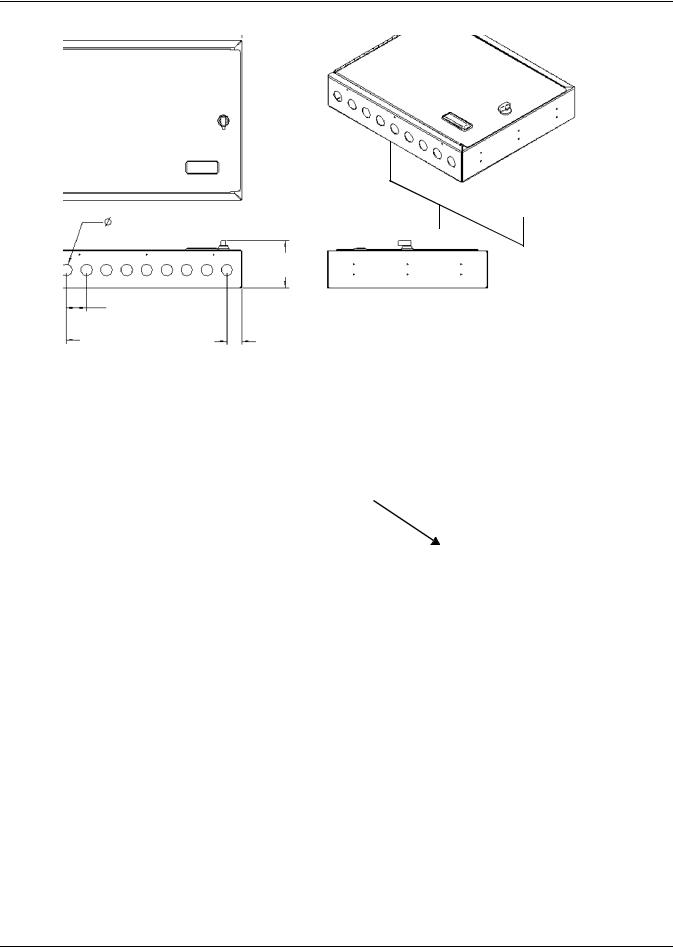
2.2Enclosure Diagrams
Figure 2 Module dimensions, without enclosure
SL12E |
|
Module |
|
|
|
|
|
|
|
|
|
|
|
|
|
ARCnet transmit |
|
Status |
|
|
|
|
|
|
|
|
|
|
|
|
|
ARCnet receive |
|
|
|
|
|
|
|
|
|
|
|
|
|
|
|
|
|
|
|
Error Codes: |
|
|
|
|
|
|
|
|
|
|
|
|
|
|
|
|
Chase = OK |
|
|
|
|
|
|
|
|
|
|
|
|
|
Archive Valid |
|
|
|
|
|
|
|
|
|
|
|
|
|
|
|
Port S1 transmit |
||
|
0 |
= Download required |
|
|
|
|
|
|
|
|
|
|
|
|
|
|
|
1 |
2 |
3 |
4 |
5 |
6 |
7 |
8 |
0 |
|
|
0 |
|
Port S1 receive |
||
|
1 |
= Control Program Error |
1 |
9 |
1 |
|
||||||||||
|
|
|
|
|
|
|
|
9 |
|
2 |
|
2 |
Battery low |
|||
10/100 BaseT |
2 |
= RAM full |
|
|
|
|
|
|
|
8 |
|
3 |
8 |
|
3 |
|
|
|
|
|
|
|
|
7 |
5 |
7 |
5 |
|
|||||
3 |
= Comm setup error |
|
|
|
|
|
|
|
6 |
4 |
6 |
4 |
|
|||
Ethernet Port |
4 |
= System error |
|
|
|
|
|
|
|
|
|
|
|
|
|
|
|
8 |
= Formatting |
|
Power |
|
3V Lithium Battery 10's |
|
|
|
|
||||||
|
|
Blinking Dot= “Run” |
|
|
|
|
1's |
|
||||||||
|
|
|
|
LED |
|
|
|
CR-123A |
|
Module |
|
|||||
|
|
|
|
|
|
|
|
|
|
|
|
|
||||
100 LAN LINK |
|
|
|
|
|
|
|
|
|
|
|
Address |
|
|||
BACnet® |
|
|
|
|
|
|
Sw |
1 |
|
2 |
3 |
|
|
4 |
5 |
|
Over ARCNET156 KBaud |
|
|
|
|
|
|
On |
|
Assigned +100 |
|
|
Enable |
Enable |
|||
BT485 |
|
|
|
|
|
|
|
|
|
|
|
|
|
|
|
|
7-7/8" 200mm
Net + |
ARCnet |
|
Net - |
|
|
Port |
|
|
|
|
|
Shield |
|
|
Gnd |
|
|
Rnet + |
Rnet |
Local |
Rnet - |
Access |
|
|
|
|
+12V |
|
|
Xnet + |
Xnet |
|
Xnet - |
Remote |
|
Gnd |
Expansion |
|
|
|
Port 1 |
Port 2 |
Port 3 |
Port 4 |
Port 5 |
Net+ Net- |
Net+ Net- |
Net+ Net- |
Net+ Net- |
Net+ Net- |
Off |
Default |
0 |
Disable |
Disable |
Enhanced Access IP Addr |
Address |
MSTP |
PTP |
|
on Rnet |
|
|
on S1 |
on S1 |
EIA-232
485-4w
SiteLink-E 485-2w
SSW-12E
Ports 9- 12
4 wire |
Tx+ |
Tx- |
Rx+ |
Rx- |
2 wire |
Net+ |
Net- |
n/c |
n/c |
EIA-232 |
Tx |
Rx |
Gnd |
n/c |
Port 6 |
Port 7 |
Port 8 |
|
|
|
Net+ Net- |
Net+ Net- |
Net+ Net- |
Port 9 |
Port 10 |
Port 11 |
|
|
|
24Vac, 24VA, 1A, 50-60 Hz
26Vdc, 10W, 0.4A
Use Copper Conductors Only Class 2
Ground 24ac/26dc
Power
|
|
|
On Off |
|
|
|
|
External |
Gnd |
|
|
|
Battery |
+3V |
|
|
|
Ext. Batt . |
|
|
|
|
Int . Batt . |
|
485 |
Port S1 |
|
||
EIA- |
|
|||
2 wire 4 wire EIA-232 |
|
|||
|
Signal Ground |
|
||
|
n/c |
Rx- |
DCD |
|
|
n/c |
Rx+ DTR |
|
|
|
Net- |
Tx- |
Rx |
|
|
Net+ Tx+ |
Tx |
|
|
Port 12
Ports 9-12
EIA -485
EIA -232
BT485
11-5/16" 287mm
Dimensions are identical for Liebert Sitelink-2E Liebert Sitelink-4E Liebert Sitelink-12E
2
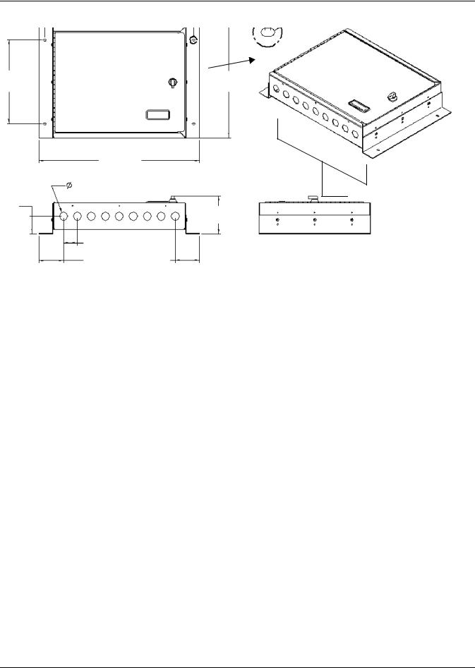
Installing the Liebert SiteLink-E Module
Figure 3 Enclosure dimensions—overall
14.25"
(362mm)
12"
(304.8mm)
Wiring knockouts (Top and Bottom)
2.85" |
0.88" |
9 places each end |
(72.3mm) |
(22.2mm) |
|
|
|
|
3.55"
(90.1mm)
1.38" |
1.5" |
(34.9mm) |
(38.1mm) |
1.12" |
1.12" |
(28.6mm) |
(28.6mm) |
Figure 4 Enclosure dimensions—Wall mount
0.88" |
12.5" |
0.88" |
(22.2mm) |
(317.5mm) |
(22.2mm) |
|
|
1" |
|
A |
(25.4mm) |
|
|
DETAIL A |
12" |
Back of Liebert |
2 places |
SiteLink-E Enclosure |
|
|
(304.8mm) |
|
|
|
|
12 |
|
|
places |
|
|
0.2" |
|
|
(5.4mm) |
|
|
1" |
|
|
(25.4mm) |
0.88" |
|
0.88" |
(22.2mm) |
|
(22.2mm) |
Dimensions are identical for Liebert Sitelink-2E Liebert Sitelink-4E Liebert Sitelink-12E
R 0.11"(2.7mm)
0.4"
(10.2mm)
R 0.19"(4.7mm)
Dimensions are identical for Liebert Sitelink-2E Liebert Sitelink-4E Liebert Sitelink-12E
3
Installing the Liebert SiteLink-E Module
Figure 5 Enclosure dimensions—Floor mount
16" |
0.16" |
(406.4mm) |
|
|
(4mm) |
|
R 0.11" |
|
(2.8mm) |
BDETAIL B 14 places
9"
(228.6mm)
17.25"
(438.2mm)
0.88" 9 places each end (22.2mm)
1.88"
47.6mm)
1.5"
(38.1mm)
2.62" 2.62" (66.7mm) (66.7mm)
4.05"
(102.8mm)
Wiring knockouts (Top and Bottom)
Dimensions are identical for Liebert Sitelink-2E Liebert Sitelink-4E Liebert Sitelink-12E
4
Loading...