

Page 1
EU Valve
D102004X012
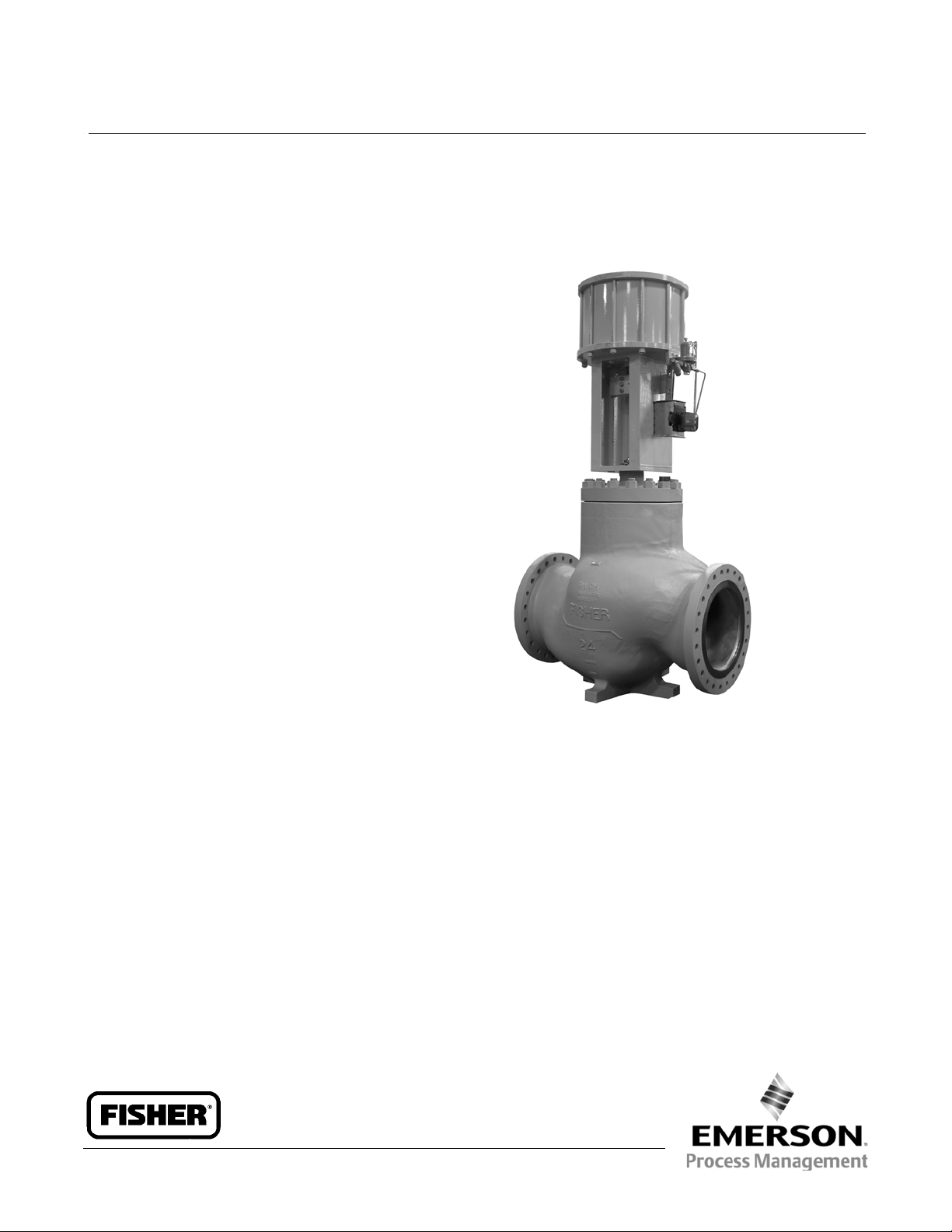
Fisherr EU and EW Valves
NPS 16 through 24 x 20
The Fisher NPS 16 through 24 × 20 CL150 through
CL600 EUT-2, EWT-2, EUD, EWD, EUT, and EWT control
valves (figures 3 and 4) are used for either throttling or
on-off control of a wide variety of liquids and gasses.
CL900 NPS 16 and 20 x 16 valves are available upon
request. Please contact your Emerson Process
Management sales office for more details. These
valves have single ports, balanced valve plugs, and
cage guiding.
EUT-2andEWT-2valveswithahangingcage(figure3)
are available for demanding applications in oil and
natural gas to 232_C(450_F). The hanging cage, with
the seat ring threaded into the cage, gives these valves
easy-maintenance trim--no trim parts are threaded
into the valve body. The seal between the plug and
cage and the seal between the seat ring and valve body
are spring-loaded PTFE seals.
Product Bulletin
51.1:EU
September 2014
EUD and EWD valves (figure 4) have a bolted-in seat
ring. These valves have metal-to-metal seating and use
two graphite piston rings between the valve plug and
cage. They are used primarily for high temperature
(over 232_C[450_F]) service. The Bore Seal is used to
obtain Class V shutoff above 316_C (600_F).
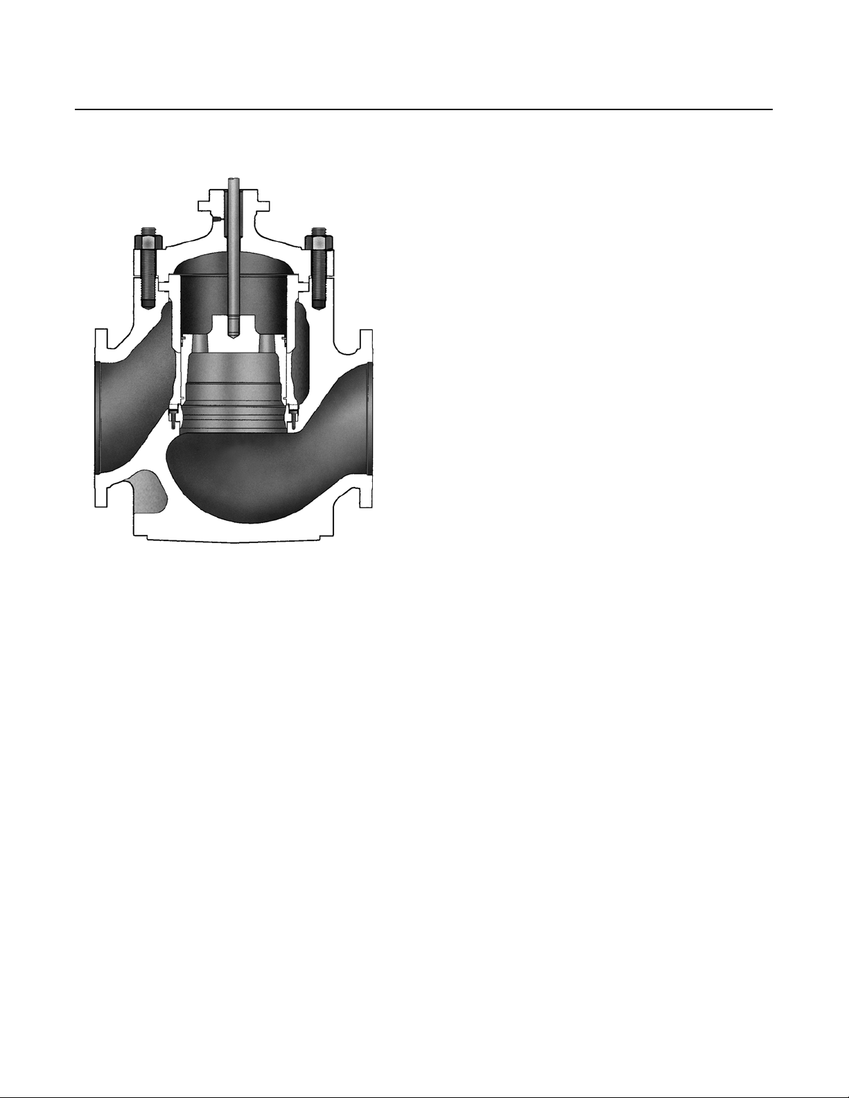
EUT and EWT valves (figure 1) have a bolted-in seat
ring. These valves have metal-to-metal seating and use
PEEK anti-extrusion rings to obtain temperatures up to
316_C(600_F).
Thesevalvessharethefollowingcharacteristics:
multiple trim material choices, trim part
interchangeability, and different cage styles to provide
particular flow characteristics to handle specific
applications.
W9156-2
To help reduce aerodynamic noise in gas service,
Whisper Trimt III (figure 5) and WhisperFlot cages
are available. To eliminate liquid cavitation damage,
Cavitrolt III cages are available. For cavitating liquids
with particulate, DST (dirty service trim) is available.
www.Fisher.com
Page 2

Product Bulletin
51.1:EU
September 2014
Specifications
EU Valve
D102004X012
Valve Sizes
EUT-2, EUD, and EUT:
EWT-2, EWD, and EWT:
J 24 x 16, and J 24 x 20 valves (size designations
J NPS 16 and J 20
J NPS 20 x 16,
are end connection size x nominal trim size)
Construction Materials
Valve Body and Bonnet:
J LCC steel, or J CF8M (316 stainless steel). For
other materials, consult your Emerson Process
Management sales office
Trim and Other Parts: Seetables1,2,and3.
End Connection Styles
Flanged: CL150, 300, and 600 raised-face or ring-type
joint flanges per ASME B16.5
Buttwelding: All ASME B16.25 schedules through
schedule 120 that are compatible with the ASME
B16.34 valve body rating
For other end connections, contact your Emerson
Process Management sales office for details.
Maximum Inlet Pressure
(1)
Flanged: Consistent with CL150, 300, and 600
Flow Characteristics
Standard Cages:
Whisper Trim III and Cavitrol III Cages: Linear
WhisperFlo Cages: Linear
For other characteristics, contact your Emerson
Process Management sales office for details.
Flow Direction
Standard and Cavitrol III Cages: Down
Whisper Trim III Cages: Up
WhisperFlo Cages: Up
pressure-temperature ratings per ASME B16.34
Buttwelding: Consistent with CL600 per
ASME B16.34
Material Temperature and Pressure Drop
Capabilities
(1)
Flow Coefficients
See Fisher Catalog 12
Port Diameters
See tables 6 and 7
See table 1 and figures 6 and 7.
Valve Plug Travel
Shutoff Classifications per ANSI/FCI 70-2andIEC
60534-4
EUT and EWT with Metal Seats
102 through 432 mm (4 to 17 inches).
Contact your Emerson Process Management sales
office for further details if needed
Standard: Class V
EUT-2andEWT-2withMetalSeats
Standard (for all trims except 2
-
Stage Cavitrol Trim):
Class IV
Standard (for 2
Optional (for all trims except 2
-
Stage Cavitrol Trim): Class V
-
Stage Cavitrol Trim):
Class V
EUT-2andEWT-2 with Soft Metal Seats
Class V
EUDandEWDwithMetalSeats
Standard: Class III
Optional: Class IV and V
1. The pressure/temperaturelimits in this bulletin andany applicable standardor code limitation for valve should not be exceeded.
Yoke Boss and Stem Diameters
J 127 mm (5-inch) or J 127 mm (5H-inch) diameter
yoke boss, each with 31.8 mm
(1.25 inch) diameter valve stem
Typical Bonnet Style
Standard Plain (style 1 extension)
Approximate Weights
Seefigure8
J WCC steel, J WC9 steel,
J Linear or J equal percentage
2
Page 3
EU Valve
D102004X012
Figure 1. Fisher EUT / EWT Valve with PEEK Anti-Extrusi on Rings
Product Bulletin
51.1:EU
September 2014
W9518-1
Features
Stable Control at High Pressure Drops-- Rugged
cage guiding stabilizes the valve plug at all points in
itstravelrange.Thisguidingreducesvibration,
mechanical noise, and the need for hydraulic
snubbers.
Economy-- Streamlined flow passages provide
greater capacities per initial investment than most
globe valves of the same size. Balanced valve plug
design can allow use of smaller actuators for high
pressure drops.
Cost-Effective Operation-- Increased wear
resistance of the standard hardened stainless steel
trim means long-lasting service.
Easy Maintenance-- The valve can stay in the
pipeline during removal of trim parts for inspection
or maintenance.
3
Page 4
Product Bulletin
51.1:EU
September 2014
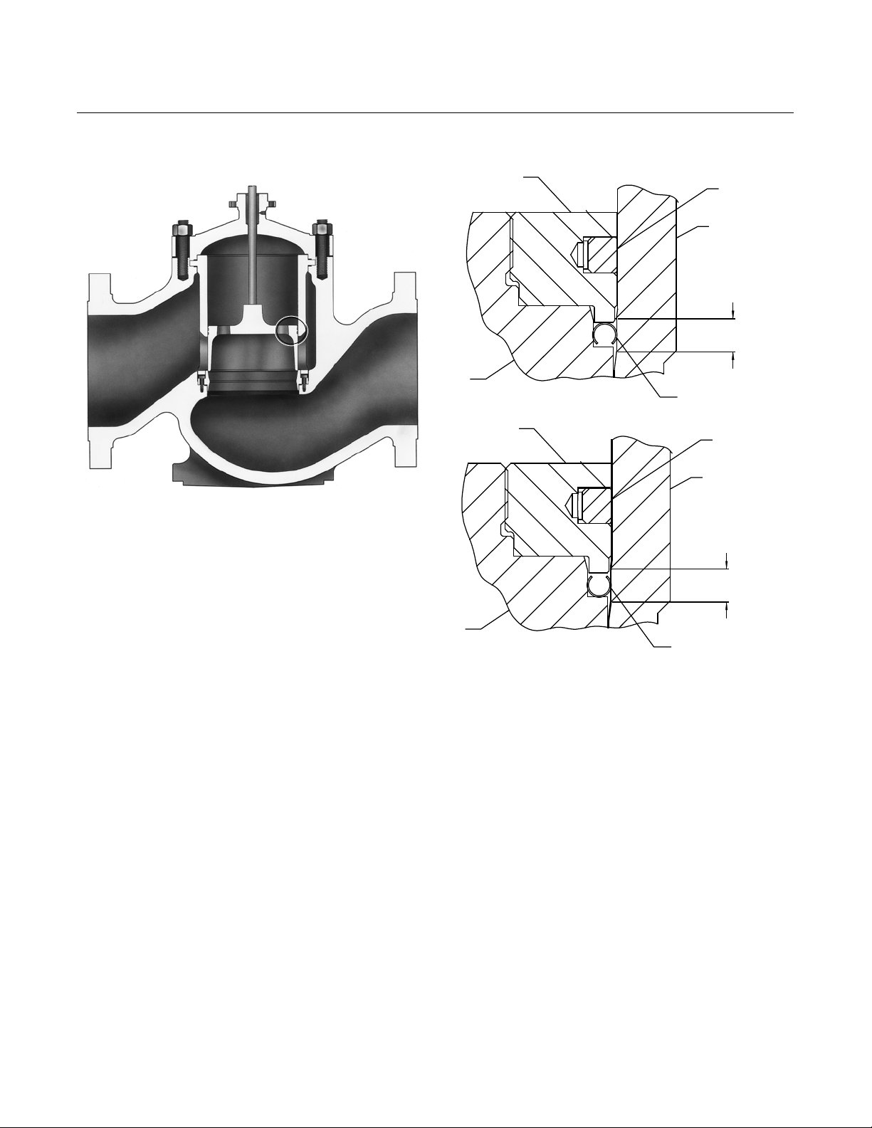
Figure 2. Typical Fisher EUD with Bore Seal
A
RETAINER
EU Valve
D102004X012
PISTON RING
CAGE
SEATING AREA
W6022-2
Bore Seal Description
TheBoreSeal(figure2)isavailablefortheEUDand
EWD only and is required for Class V shutoff
applications where the service temperature exceeds
316_C(600_F). For service temperatures below 316_C
(600_F), the EWT and EUT should be used when Class
V shutoff is required. See table 4 for availability and
temperature limits and figure 2.
TheBoreSealemploysametalCshaped seal ring that
PLUG
RETAINER
PLUG
FLOW DOWN
FLOW UP
VIEW A
BORE SEAL
PISTON RING
CAGE
SEATING AREA
BORE SEAL
is secured to the outside diameter of the valve plug.
When the valve plug comes into contact with the seat
ringtoclosethevalve,theBoreSealiscompressed
against the cage wall, thereby blocking a secondary
leakage path that exists between the plug and cage
wall. When the valve plugis not in contact with the
seat ring (i.e. valve open), theBoreSealisnotengaged
and the piston rings that are also secured to the
outsidediameteroftheplugassumetheroleof
blocking this secondary leakage path.
4
Page 5

EU Valve
D102004X012
Figure 3. Typical Fisher EUT-2 or EWT-2 Valve
TAPPED BONNET
(OPTIONAL)
BONNET GASKET
CAGE GASKET
HANGING CAGE DESIGN
SEAT RING
THREADED
TO CAGE
Product Bulletin
51.1:EU
September 2014
W6088-2
COMPLETE VALVE
SEAT RING
THREADED TO
CAGE
SEAL RING
W6089-1A
SEAT RING SEAL DETAIL
5
Page 6

Product Bulletin
51.1:EU
September 2014
Figure 4. Typical Fisher EUD or EWD Valve
EU Valve
D102004X012
W6022-2
Figure 5. Fisher EWT-2 Valve with Whisper Trim III D3 Cage, Baffle, and Lower Metal Piston Ring
BAFFLE
CAGE
W6202-2
6
Page 7
EU Valve
D102004X012
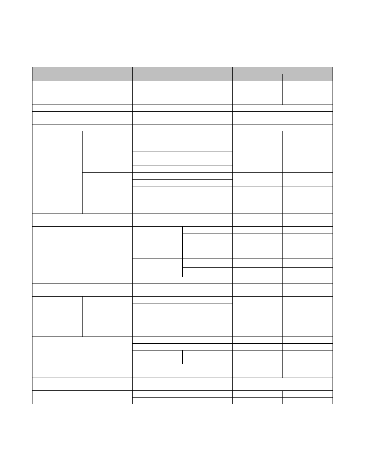
Table 1. Construction Materials
PART MATERIAL
Valve Body and Bonnet
Cage, Seat Ring, and ValvePlug See tables 2 and 3 See figures 6 and 7
Soft Metal Seat (with trim 233 in EUT-2andEWT-2
Valve-to-Bonnet
Bolting
Bonnet, Seat Ring, and Cage Gaskets N06600/Graphite
EUD and EWD Piston Ring or Lower Graphite
Piston Ring (254 mm[10 inch] port only)
EUT-2andEWT-2SeatRingSealRing
EUT and EWT valves
with PEEK
anti-extrusion rings
For applications using a
lower metal piston ring
Packing (Temperatures shown are in-body
temperatures with plain bonnet.)
Packing Flange, Studs, and Nuts
Packing Follower, Spring (PTFE V-Ring Packing), or
valves only)
Valve Stem S20910 SST Not a Limiting Factor
WCC Valve
LCC Valve
WC9 Valve
CF8M Valve
Seat Ring Cap Screws
Graphite (Fisher
Designation FMS
Graphite (Fisher
Designation FMS
EUD and EWD Bore Seal N07718 -198 to593 -325 to1100
andPlugSealRing
Backup ring
Retaining ring 18-8
Seal ring PTFE/graphite with N10276 spring 232 to316 450 to 600
Lower metal piston ring Iron / N07750 -73 to427 -100 to800
Ribbon/Filament
Lantern Ring
Packing Box Ring
Product Bulletin
51.1:EU
September 2014
TEMPERATURE
_C _F
WCC Steel
WC9 Steel
CF8M (316 Stainless Steel)
17F27)
17F39)
N10276/Glass and Moly-Filled PTFE -73 to232 -100 to450
Graphite
S31600 (316Stainless Steel) -198 to593 -325 to1100
LCC
CF8M See figures 6 and 7
SA-193-B7 Studs
SA-194-2H Nuts
SA-193-B7 Studs
SA-194-2H Nuts
SA-193-B7 Studs
SA-194-2H Nuts
S20910 CrCtStuds
S20910 Nuts
B8M Class 2 studs
8M nuts
SA-193-B7 Studs
SA-194-2H Nuts
S17400
N07718
Oxidizing -198 to 427 -325 to 800
Non-Oxidizing -198 to593 -325 to1100
Oxidizing -198 to 427 -325 to 800
Non-Oxidizing -198 to482 -325 to900
Oxidizing -198 to 538 -325 to 1000
Non-Oxidizing -198 to593 -325 to1100
S41000
S31600
PTFE V-Ring -46 to 232 -50 to 450
PTFE Composition -46 to232 -50 to 450
Oxidizing -198 to 354 -325 to 700
Non-Oxidizing -198 to538 -325 to1000
Steel -29 to427 -20 to 800
S31600 Not a Limiting Factor
S17400 -101 to 427 -150 to800
S31600 -198 to 593 -325 to1100
-29 to427
-29 to593
-198 to593
-46 to343
-29 to427 -20 to 800
-46 to343 -50 to 650
-29 to427 -20 to 800
-198 to538 -325 to1000
-198 to427 -325 to800
-29 to427 -20 to 800
-29 to354
-198 to593
Not aLimiting Factor Not a Limiting Factor
-20 to 800
-20 to1100
-325 to1000
-50 to 650
-20 to 700
-325 to1100
7
Page 8

Product Bulletin
51.1:EU
September 2014
EU Valve
D102004X012
Table 2. Typical Combinations of Metal Trim Materials for All Valves Except Those with WhisperFlo Trim
Valve Design Trim Designation Valve Plug Seat Ring Cage
(2)
231
EUT-2, EWT-2
EUD, EWD
EUT, EWT
1. For WhisperFlo trims, see table 3.
2. Cavitrol IIIcage is standardwith trim 231
3. NACE MR0175approved trim materials.
(3)
232
226 CA6NM CB7CU-1 H1075 CB7CU-1 H1075 S17400 H1100
227A
(3)
229
229H
231 CA6NM HT CB7CU-1 H1075 CB7CU-1 H1075 S17400 H1100
(3)
232
(3)
CA6NM HT CB7CU-1 H1075 CB7CU-1 H1075 ---
CF8M with CoCr-A
on Seatand Guide
WC9 Steel with
CoCr-AonSeatand
Guide
CF8M with CoCr-A
on Seatand Guide
CF8M with CoCr-A
on Seatand Guide
CF8M with CoCr-A
on Seatand Guide
CF8M with CoCr-A
on seat
CF8M with CoCr-A
on seat
CF8M with CoCr-A
on seat
CF8M with CoCr-A
on seat
CF8M with CoCr-A
on seat
CF8M ENC ---
WC9 Nitrided N07718
CF8M ENC N07718
CF8M
Chrome-Coated
CF8M ENC N07718
Seat Ring Cap
Screws
N07718
Table 3. WhisperFlo Metal Trim Materials and Valve Body/Trim Temperature Capabilities
Valve Design Trim Designation Valve Plug Seat Ring Cage
952 CA6NM HT
EUT-2, EWT-2
953
950 CA6NM HT
EUD, EWD
951
952 CA6NM HT
EUT, EWT
953
1. NACE MR0175approved trim materials.
CF8M with CoCr-A
on seat
(1)
(1)
(1)
CF8M with CoCr-A
on Seatand Guide
CF8M with CoCr-A
on Seatand Guide
CF8M with CoCr-A
on Seatand Guide
CF8M with CoCr-A
on seat
CF8M with CoCr-A
on seat
CF8M with CoCr-A
on seat
CF8M with CoCr-A
on seat
CF8M with CoCr-A
on seat
410 SST/
ENC/Ultimet
316L SST/
ENC/Ultimet
410 SST/
ENC/Ultimet
316L SST/
ENC/Ultimet
410 SST/
ENC/Ultimet
316L SST/
ENC/Ultimet
Seat Ring Cap
Screws
---
---
N07718
N07718
N07718
N07718
(1)
Temperature
Seefigure6
Seefigure7
Seefigure7
Temperature
Seefigure6
Seefigure7
Seefigure7
Table 4. Bore Seal Availability and Temperature Capabilities (EUD/EWD only)
Valve Design Valve Size, NPS Trim Designation Temperature ANSI/FCI/IEC Shutoff Class
226
EUD and EWD 16, 20x16,24x16, 20, 24x20
8
227A
950
Seefigure7 V
Page 9

Product Bulletin
EU Valve
D102004X012
Figure 6. Temperature and Pressure Drops for Typical Trim Used in Fisher EUT-2 and EWT-2 Valves
FLUID TEMPERATURE, _C FLUID TEMPERATURE, _C
September 2014
51.1:EU
FLUID TEMPERATURE, _F
FOR STANDARD METAL SEATING WITH CL600
MC140-1/AR1
A6890
Notes:
1
higher capabilities.
WCC/LCC STEEL BODY
Do not exceed the maximum pressure and temperature for the class rating of the body materialused, even though thetrims shown may have
FLUID TEMPERATURE, _F
FOR STANDARD METAL SEATING WITH CL600
CF8M (316 STAINLESS STEEL) BODY
9
Page 10

Product Bulletin
51.1:EU
September 2014
Figure 7. Temperature and Pressure Drops for Typical Trim Used in Fisher EUD, EWD, EUT, and EWT Valves
FLUID TEMPERATURE, _C
952, 953
231, 232
3
FLUID TEMPERATURE, _C
D102004X012
EU Valve
FLUID TEMPERATURE, _F
FOR STANDARD METAL SEATING WITH CL600
WCC STEEL BODY
MC140-2/AR1
A6891
FOR STANDARD METAL SEATING WITH CL600
FLUID TEMPERATURE, _F
WC9 CHROME MOLY STEEL BODY
FLUID TEMPERATURE, _C
229
229H
226
229
229H
226
229H
951
229H
229H
FLUID TEMPERATURE, _F
FOR STANDARD METALSEATING WITH CL600
CF8M (316 STAINLESS STEEL) BODY
Notes:
1
2
3
Do not exceed the maximum pressure andtemperature forthe classrating ofthe bodymaterial used,even thoughthe trimsshown mayhave highercapabilities.
482_C (900_F)limit -- WCC steel valve plug
371_C (700_F)limit --S17400 seat ring bolting
316_C (600_F)limit --EUT andEWT valves with 231,232, 952, and 953 trims
10
Page 11

Product Bulletin
EU Valve
D102004X012
Table 5. Dimensions and Approximate Weights
END
CONNECTION
Size,
NPS
16
20 × 16
20
24 × 16
24 × 20
1. RF--raised face; RTJ--ring-type joint; BW--buttwelding.
2. For longertravels, the neck of the valve (the portion of the valve body that supports the bonnet) is longer to accommodate the travel. The longer neck increases the Ddimension.
Type
APPROXIMATE
WEIGHT
(LONG-NECK
(2)
VALVE
(1)
Kg Lb mm Inch mm Inch mm Inch mm Inch mm Inch mm Inch mm Inch mm Inch
RF
2540 5600
RTJ 1026 40.38 1073 42.25 1111 43.75
BW 2270 5000 --- --- --- --- 1108 43.62
RF
3540 7800
RTJ 1276 50.25 1327 52.25 1378 54.25
BW 3130 6900 --- --- --- --- 1372 54.00
RF
5220 11500
RTJ --- --- --- --- --- ---
BW 4810 10600 --- --- --- --- 1372 54.00
RF
5220 11500
RTJ 1565 61.62 1623 63.88 1686 66.38
BW 4630 10200 --- --- --- --- 1676 66.00
RF
7710 17000
RTJ 1565 61.62 1623 63.88 1686 66.38
BW 7120 15700 --- --- --- --- 1676 66.00
CL150 CL300 CL600
1016 40.00 1057 41.62 1108 43.62
1267 49.88 1308 51.50 1372 54.00
1267 49.88 1308 51.50 1372 54.00
1556 61.25 1600 63.00 1676 66.00
1556 61.25 1600 63.00 1676 66.00
A
DIMENSION
Standard Plain Bonnet (Style 1 Extension)
G
437 17.19 663 26.12 127 5.00 816 32.12 226 8.88
487 19.19 706 27.81 226 8.88 859 33.81 276 10.88
514 20.25 917 36.12 276 10.88 1121 44.12 378 14.88
526 20.69 816 32.12 226 8.88 1121 44.12 378 14.88
565 22.25 917 36.12 276 10.88 1121 44.12 378 14.88
Short-Neck Valve
D Max. Travel D Max. Travel
(2)
September 2014
Long-Neck Valve
51.1:EU
(2)
Figure 8. Dimensions and Approximate Weights (also see table 5)
A6068
31.8
(1.25)
STEM
DIAMETER
A
2
25
(1.00)
A
MATCH LINE FOR 585C ACTUATORS
AND 657,667, SIZE 100 ACTUATORS
MATCH LINE
FOR ALL OTHER
ACTUATORS
D
G
mm
(INCH)
11
Page 12

Product Bulletin
51.1:EU
September 2014
Table 6. Port Diameters for Fisher EUT-2andEWT-2 CL 150 through CL600 Valves
Valve Size, NPS TRIM
Cast cages
16
20 × 16
24 × 16
20
24 × 20
1. Linear or equal percentage.
Drilled cages
Drilled cages
Drilled cages
Drilled cages
Whisper Trim III A, B, and C 412.8 16.25
Cast cages
Cast cages
(1)
, WhisperFlo, and Cav III 374.7 14.75
Whisper Trim III D 355.6 14.00
(1)
, WhisperFlo, and Cav III 374.7 14.75
(1)
and Whisper TrimIII A,B, and C 412.8 16.25
Whisper Trim III D 355.6 14.00
(1)
, WhisperFlo, and Cav III 374.7 14.75
(1)
and Whisper TrimIII A,B, and C 412.8 16.25
Whisper Trim III D 355.6 14.00
WhisperFlo and Cav III 463.6 18.25
(1)
and Whisper TrimIII A,B, and C 501.7 19.75
Whisper Trim III D 431.8 17.00
WhisperFlo and Cav III 463.6 18.25
(1)
and Whisper TrimIII A,B, and C 501.7 19.75
Whisper Trim III D 431.8 17.00
mm Inches
EU Valve
D102004X012
PORT DIAMETER
Table 7. Port Diameters for Fisher EUD, EWD, EUT and EWT CL 150 through CL600 Valves
Valve Size, NPS TRIM
Linear; Equal Percentage; Whisper Trim III A, B,
16
20 × 16
24 × 16
20
24 × 20
and C; WhisperFlo; and Cav III
Whisper Trim III D 355.6 14.00
Linear; Equal Percentage; Whisper Trim III A, B,
and C; WhisperFlo; and Cav III
Whisper Trim III D 355.6 14.00
Linear; Equal Percentage; Whisper Trim III A, B,
and C; WhisperFlo; and Cav III
Whisper Trim III D 355.6 14.00
Linear; Equal Percentage; Whisper Trim III A, B,
and C; WhisperFlo; and Cav III
Whisper Trim III D 431.8 17.00
Linear; Equal Percentage; Whisper Trim III A, B,
and C; WhisperFlo; and Cav III
Whisper Trim III D 431.8 17.00
mm Inches
374.7 14.75
374.7 14.75
374.7 14.75
463.6 18.25
463.6 18.25
Neither Emerson, Emerson Process Management, nor any of their affiliated entities assumes responsibility for the selection, use or maintenance
of anyproduct. Responsibility for proper selection, use, and maintenance of any product remains solely with the purchaser andend user.
Fisher, Whisper Trim,WhisperFlo, andCavitrol are marks owned by one of the companies inthe EmersonProcess Management business unitof Emerson
Electric Co. Emerson Process Management, Emerson, and the Emerson logo are trademarks and service marks of Emerson Electric Co. All other marks are
the property of their respective owners.
The contents of this publication are presented for informational purposes only, and while every effort has been made to ensure their accuracy, they arenot
to be construed as warranties orguarantees, express or implied, regarding the products or services described herein or their use or applicability. All sales are
governed by our terms and conditions, which are availableupon request. We reserve the right to modify or improve the designs or specificationsof such
products at any time without notice.
Emerson ProcessManagement
Marshalltown, Iowa 50158 USA
Sorocaba, 18087 Brazil
Chatham, Kent ME4 4QZ UK
Dubai, United Arab Emirates
Singapore 128461 Singapore
www.Fisher.com
PORT DIAMETER
E 1992, 2014 Fisher ControlsInternational LLC. All rightsreserved.
12
 Loading...