

Emerson fisher ETR, fisher EDR Instruction Manual
Instruction Manual
D100391X012
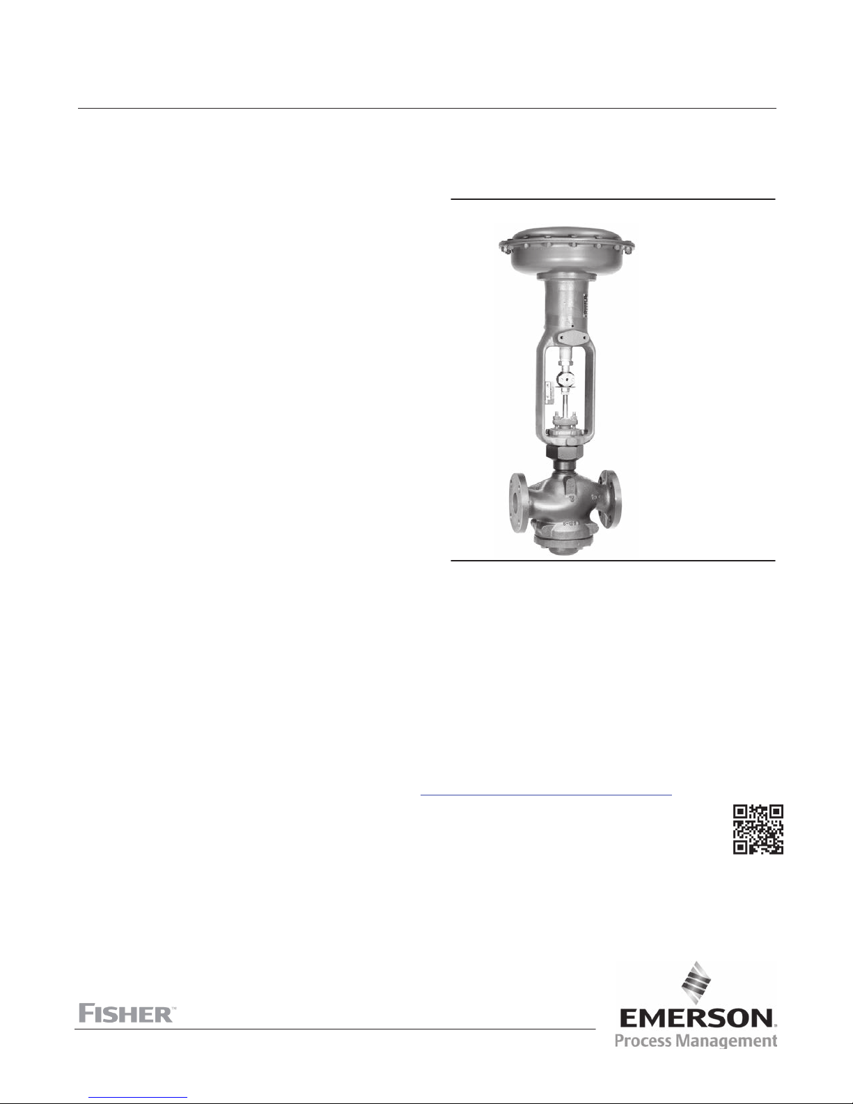
Fisher™ EDR and ETR easy-e™ Valves
EDR and ETR Valves
March 2016
Contents
Introduction 1.................................
Scope of Manual 1.............................
Description 1.................................
Specifications 2...............................
Educational Services 2.........................
Installation 4..................................
Maintenance 5.................................
Trim Maintenance 5...........................
Packing Maintenance 9.........................
Parts Ordering 15...............................
Packing Kits 16.................................
Parts Kits 19...................................
Parts List 20...................................
Introduction
Figure 1. Reverse Acting easy‐e Valve with Actuator
W2080‐1
Scope of Manual
This instruction manual includes installation, maintenance, and parts information for NPS 1 through 4 EDR and ETR
valves (see figure 1). The valves are available in CL150 through 600 ratings.
The valves are also available with full‐size and restricted‐trim designs. Refer to separate manuals for instructions
covering the actuator and accessories.
Do not install, operate, or maintain an EDR or ETR valve without being fully trained and qualified in valve, actuator, and
accessory installation, operation, and maintenance. To avoid personal injury or property damage, it is important to
carefully read, understand, and follow all the contents of this manual, including all safety cautions and warnings. If you
have any questions about these instructions, contact your Emerson Process Management sales office
proceeding.
before
Description
The EDR and ETR are single‐port, globe‐style valves that feature cage guiding, a balanced plug design, and
push‐down‐to‐open valve plug action. The valve constructions are available with metal‐to‐metal or
metal‐to‐composition seats. These constructions permit access to the internal trim parts through the bottom flange
without removing the actuator from the valve.
www.Fisher.com

EDR and ETR Valves
March 2016
Table 1. Specifications
Instruction Manual
D100391X012
Available Valve Constructions
See table 2
Shutoff Classification
EDR: ANSI/FCI 70‐2 and IEC 60534‐4 Class II
(standard); Class III for valves with a graphite piston
ring and 78 mm (3.4375 inch) or larger port diameter
End Connection Styles
Cast Iron Valves
Flanged: CL125 flat‐face or 250 raised‐face flanges per
ASME B16.1
Steel and Stainless Steel Valves
Flanged: CL150, 300, and 600 raised‐face or ring‐type
joint flanges per ASME B16.5
Screwed or Socket Welding: All available ASME B16.11
ETR: Standard air test
(0.05 mL/minute/psid/inch of port diameter) using air
at service pressure drop or 3.5 bar (50 psi), whichever
is lower; or ANSI/FCI 70‐2 and
IEC 60534‐4 Class V (optional) with PTFE seats; Class
IV or V (optional) with metal seats
Flow Characteristics
Linear (all cages), quick‐opening, or equal percentage
schedules that are consistent with CL600 per ASME
B16.34
Buttwelding: Consistent with ASME B16.25
Flow Directions
Linear, Quick Opening, or Equal Percentage Cage:
Normally up,
Whisper Trimt I Cage: Always down
Maximum Inlet Pressure
(1)
Approximate Weights
Cast Iron Valves
Flanged: Consistent with CL125B or 250B
pressure‐temperature ratings per ASME B16.1
Steel and Stainless Steel Valves
Flanged: Consistent with CL150, 300, and 600
(2)
pressure‐temperature ratings per ASME B16.34
Screwed or Welding: Consistent with CL600
pressure‐temperature ratings per ASME B16.34
1. The pressure/temperature limits in this manual and any applicable standard or code limitation for the valve should not be exceeded.
2. Certain bonnet bolting material selections may require a CL600 easy‐e valve assembly to be derated. Contact your Emerson Process Management sales office
VALVE SIZE,
NPS
1 & 1‐1/4
1‐1/2
2
2‐1/2
3
4
WEIGHT
kg Pounds
14
20
39
45
54
77
.
30
45
67
100
125
170
Educational Services
For information on available courses for Fisher EDR and ETR valves, as well as a variety of other products, contact:
Emerson Process Management
Educational Services - Registration
Phone: 1-641-754-3771 or 1-800-338-8158
E-mail: education@emerson.com
http://www.emersonprocess.com/education
2
Instruction Manual
D100391X012
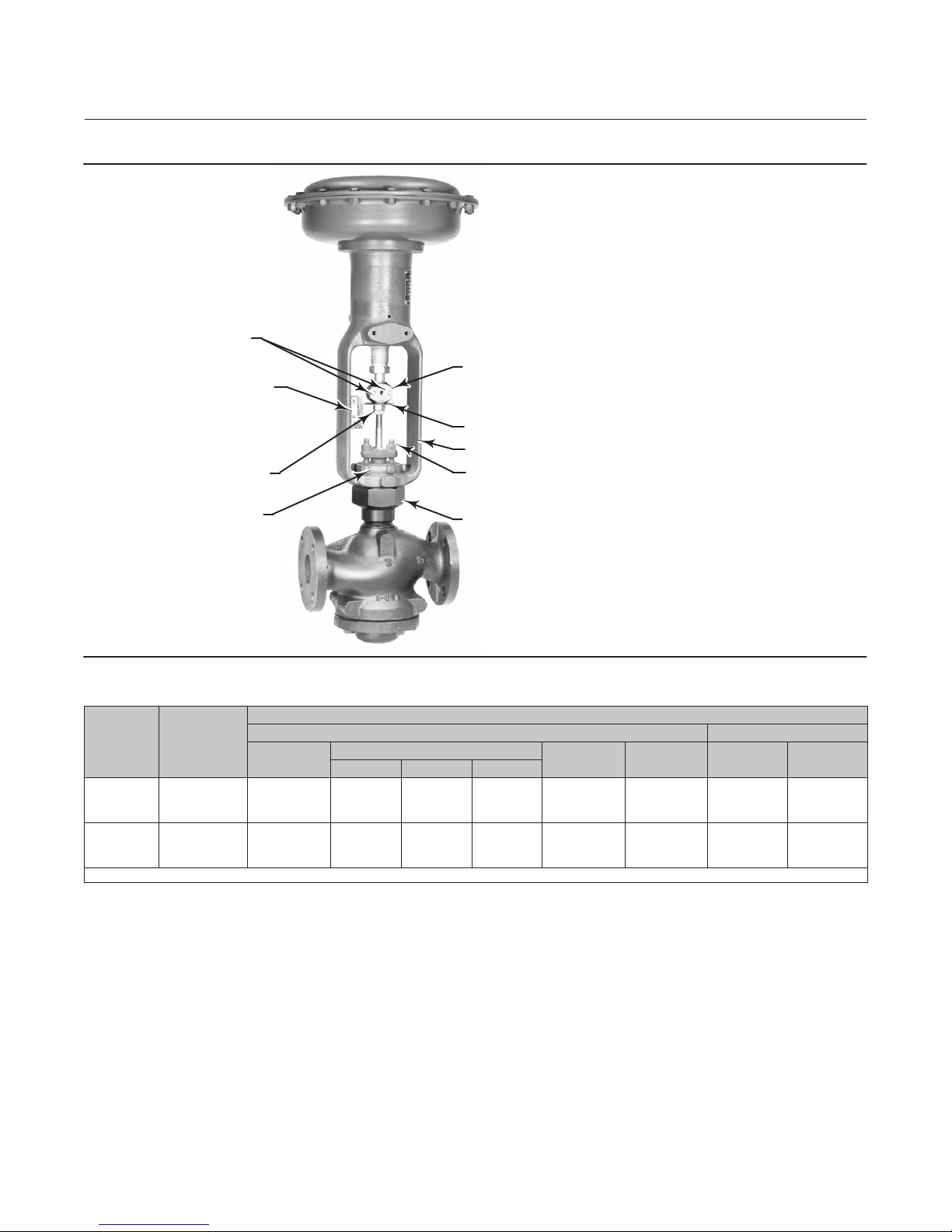
Figure 2. Actuator Mounting
CAP SCREWS
INDICATOR SCALE
STEM LOCKNUTS
EDR and ETR Valves
March 2016
STEM CONNECTOR
INDICATOR DISK
ACTUATOR YOKE
PACKING FLANGE NUTS
YOKE LOCKNUT
W2080‐1
Table 2. Available Valve Constructions
VALVE
DESIGN
EDR
ETR
X = Available Construction
VALVE
SIZE,
NPS
1, 1‐1/2, or 2
1‐1/4
2‐1/2, 3, or 4
1, 1‐1/2, or 2
1‐1/4
2‐1/2, 3, or 4
Screwed
X
X
‐ ‐ ‐
X
X
‐ ‐ ‐
BONNET
VALVE MATERIAL AND END CONNECTION STYLE
Carbon Steel, Alloy Steel, or Stainless Steel Valve Cast Iron Valve
RF or RTJ Flanged
CL150 CL300 CL600
X
‐ ‐ ‐
X
X
‐ ‐ ‐
‐ ‐ ‐
‐ ‐ ‐
‐ ‐ ‐
‐ ‐ ‐
X
X
X
X
‐ ‐ ‐
X
X
‐ ‐ ‐
‐ ‐ ‐
Butt‐
welding
X
‐ ‐ ‐
X
X
‐ ‐ ‐
‐ ‐ ‐
Socket
Weld
X
‐ ‐ ‐
‐ ‐ ‐
X
‐ ‐ ‐
‐ ‐ ‐
CL125B
FF Flanged
X
‐ ‐ ‐
X
‐ ‐ ‐
‐ ‐ ‐
‐ ‐ ‐
CL250B
RF Flanged
X
‐ ‐ ‐
X
‐ ‐ ‐
‐ ‐ ‐
‐ ‐ ‐
3

EDR and ETR Valves
March 2016
Instruction Manual
D100391X012
Installation
WARNING
Always wear protective gloves, clothing, and eyewear when performing any installation operations.
To avoid personal injury or property damage resulting from the sudden release of pressure, do not install the valve
assembly where service conditions could exceed the limits given on the valve and actuator nameplates. Use
pressure‐relieving devices as required by accepted industry, local, state, or Federal codes, and good engineering practices.
Check with your process or safety engineer for any other hazards that may be present from exposure to process media.
If installing into an existing application, also refer to the WARNING at the beginning of the Maintenance section in this
instruction manual.
CAUTION
The valve configuration and construction materials were selected to meet particular pressure, temperature, pressure drop,
and controlled fluid conditions. Because some body/trim material combinations are limited in their pressure drop and
temperature range capabilities, do not exceed these conditions without first contacting your Emerson Process
Management sales office.
Inspect the valve and pipelines to ensure they are not damaged, are clean, and free of foreign material.
1. Before installing the valve, inspect the valve and associated equipment for any damage and any foreign material.
2. Make certain the valve body interior is clean, that pipelines are free of foreign material, and that the valve is
oriented so that pipeline flow is in the same direction as the arrow (see figure 2) on the side of the valve.
3. The control valve assembly can be installed in any orientation unless limited by seismic criteria. However, the
normal method is with the actuator vertical above the valve body (see figure 2). Other positions may result in
uneven valve plug and cage wear, and improper operation. With some valves, the actuator may also need to be
supported when it is not vertical. For more information, consult your Emerson Process Management sales office
4. Use accepted piping and welding practices when installing the valve in the line. If a post‐weld heat treatment
process is to be applied to the valve end connections, and the valve has composition or elastomer trim parts,
remove the trim to avoid damage to the soft parts.
CAUTION
Depending on valve body materials used, post weld heat treating may be required. If so, damage to internal elastomeric
and plastic parts, as well as internal metal parts is possible. Shrunk‐fit pieces and threaded connections may loosen. In
general, if post weld heat treating is to be performed, all trim parts should be removed. Contact your Emerson Process
Management sales office for additional information.
5. If continuous operation is required during inspection or maintenance, install a three‐valve bypass around the
control valve assembly.
6. If the actuator and valve are shipped separately, refer to the actuator mounting procedure in the appropriate
actuator instruction manual and also see figure 2.
WARNING
.
Personal injury could result from packing leakage. Valve packing was tightened prior to shipment; however some
readjustment will be required to meet specific service conditions.
4

Instruction Manual
D100391X012
EDR and ETR Valves
March 2016
Maintenance
WARNING
Avoid personal injury from sudden release of process pressure. Before performing any maintenance operations:
D Do not remove the actuator from the valve while the valve is still pressurized.
D Always wear protective gloves, clothing, and eyewear when performing any maintenance operations to avoid personal
injury.
D Disconnect any operating lines providing air pressure, electric power, or a control signal to the actuator. Be sure the
actuator cannot suddenly open or close the valve.
D Use bypass valves or completely shut off the process to isolate the valve from process pressure. Relieve process pressure
on both sides of the valve. Drain the process media from both sides of the valve.
D Vent the power actuator loading pressure and relieve any actuator spring precompression.
D Use lock‐out procedures to be sure that the above measures stay in effect while you work on the equipment.
D The valve packing box may contain process fluids that are pressurized, even when the valve has been removed from the
pipeline. Process fluids may spray out under pressure when removing the packing hardware or packing rings, or when
loosening the packing box pipe plug.
D Check with your process or safety engineer for any additional measures that must be taken to protect against process
media.
Valve parts are subject to normal wear and must be inspected and replaced as necessary. Inspection and maintenance
frequency depends on the severity of service conditions. This section includes instructions for trim maintenance,
packing maintenance, and packing lubrication. All maintenance operations may be performed with the valve installed
in the pipeline.
Note
If the valve has ENVIRO‐SEALt live‐loaded packing installed (figure 8, 9, or 10), see the Fisher instruction manual entitled
ENVIRO‐SEAL Packing System for Sliding‐Stem Valves (D101642X012)
for packing instructions.
Trim Maintenance
Disassembly
Note
Whenever a gasket seal is disturbed by removing or shifting gasketed parts, install a new gasket upon reassembly. This is necessary
to ensure a good gasket seal.
Key number locations are shown in figure 11 or 12 unless otherwise indicated.
5
EDR and ETR Valves
March 2016
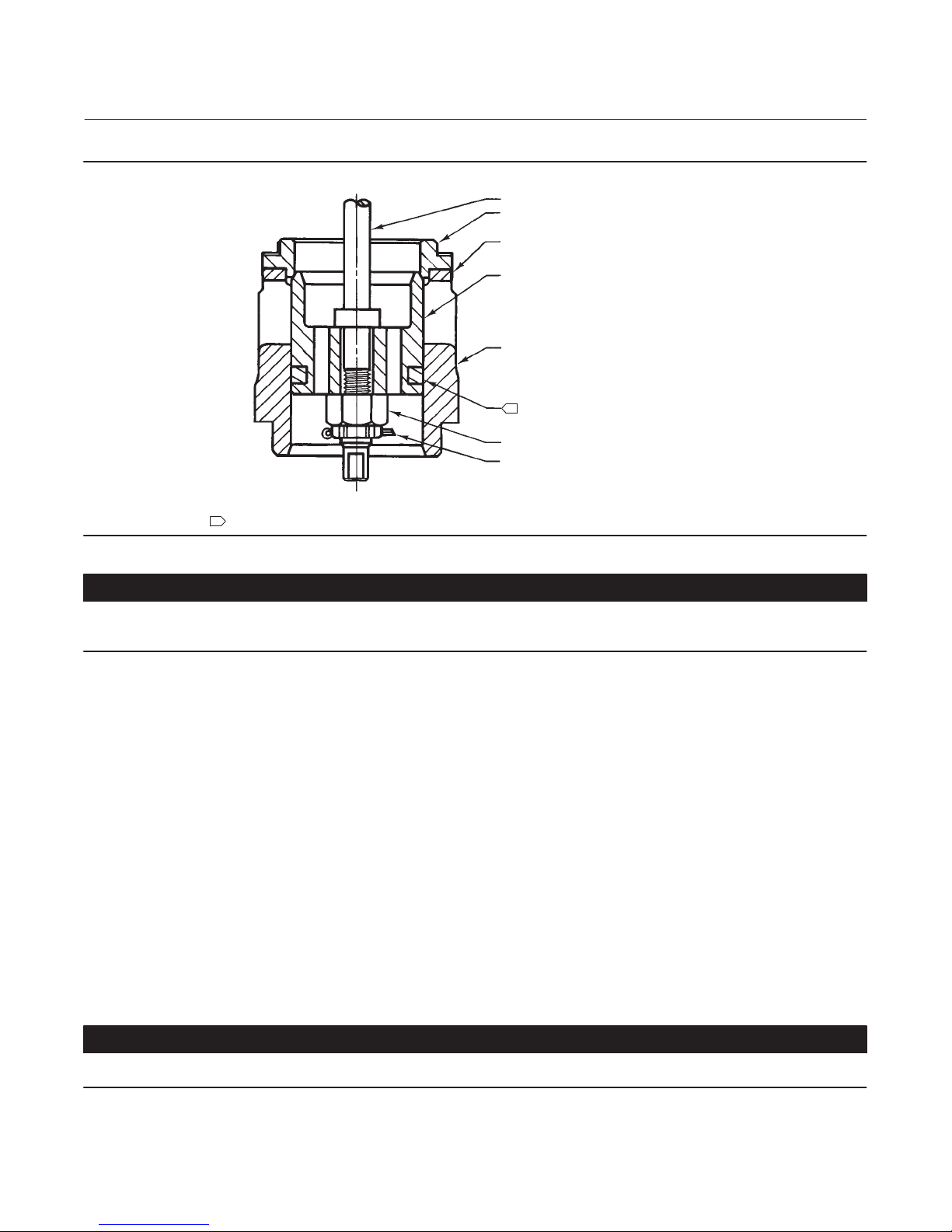
Figure 3. Valve Plug Assembly
Instruction Manual
D100391X012
STEM
DISK SEAT
DISK
VALVE PLUG
CAGE
1
40A5479‐B
B2360
NOTE:
1
ETR OR EDR
ETR USES A SEAL RING (KEY 24) AND A BACKUP RING (KEY 25) (SEE FIGURE 11).
CASTLE NUT
COTTER PIN
CAUTION
Take care when removing the bottom flange (key 31) in the following procedure, to prevent possible product damage from
parts unexpectedly falling out of the valve body.
1. Isolate the control valve from the line pressure, release pressure from both sides of the valve body, and drain the
process media from both sides of the valve. If using a power actuator, also shut off all pressure lines to the power
actuator, release all pressure from the actuator. Use lock‐out procedures to be sure that the above measures stay in
effect while you work on the equipment. When removing the bottom flange (key 31), be careful that the cage and
other parts are not damaged by unexpectedly falling out of the valve body. Remove the nuts (key 16) or cap screws
from the bottom flange.
2. Removing the valve plug from the valve body, the valve plug can be removed independently of the valve stem by
removing the cotter pin and castle nut (keys 30 and 8). Then, slide the valve plug out of the cage (see figure 3).
D Disconnect the stem connector, and loosen the packing flange nuts (see figure 2).
D Move the valve stem away from the actuator stem allowing room to remove the indicator disk and stem locknuts.
Remove the parts indicated.
D Remove the valve plug by pulling the valve plug/stem assembly through the packing and out of the bottom of the
bonnet.
D If the valve plug is to be re‐used but the stem needs to be replaced, drive the pin (key 8) out of the plug/stem
assembly and unscrew the valve stem.
CAUTION
Take care during disassembly in the following procedure, to prevent possible damage to sealing surfaces.
6

Instruction Manual
D100391X012
EDR and ETR Valves
March 2016
3. Remove the seat ring (key 9), gaskets (keys 10, 11, 12, and 13), and any remaining parts if they did not come out
with the valve plug. If the seat ring (key 9) is stuck in the valve body, strike the outside of the valve body at the seat
ring line with a rubber hammer while pulling down on the seat ring. Carefully remove the seat ring without
damaging sealing surfaces.
If necessary, machine or grind metal seats before installing the piston ring/seal ring or packing, or refer to the Lapping
Metal Seats procedure in this section.
CAUTION
The pressure balancing holes in the valve plug are necessary for the proper and safe operation of the valve. Inspect the
balancing holes every time the valve is disassembled for service. Any build-up, blockage, or clogging of the balance holes
should be removed.
Lapping Metal Seats
A certain amount of leakage should be expected with metal‐to‐metal seating in any valve body. If the leakage
becomes excessive, however, the condition of the seating surfaces of the valve plug and seat ring can be improved by
lapping. (Deep nicks should be machined out rather than ground out.) Use a good quality lapping compound of a
mixture of 280 to 600‐grit.
Assemble the valve to the extent that the seat ring (key 9), cage (key 3), cage adaptor (key 4, if used), and bonnet are
in place. Also, remove the piston ring or seal ring from the valve plug (if used).
1. Insert the valve stem (key 7) into the bonnet and thread the plug (key 2) onto the end of the stem. Make a simple
handle from a piece of strap iron; lock it to the valve with the stem locknuts.
2. Apply the lapping compound to the seating surfaces. Rotate the handle alternately in each direction to lap the
seats. After lapping the seats, remove the valve plug and stem, then clean all parts. Repeat the lapping procedure if
necessary.
Trim Assembly
Carefully clean all gasket surfaces. Use new gaskets during reassembly of the valve.
Table 3. Valve Body‐to‐Flange Nut Torques
VALVE
SIZE,
NPS
1 and 1‐1/4 129 95 64 47
1‐1/2, 1‐1/2 x 1, 2, or 2 x 1 96 71 45 33
2‐1/2, 2‐1/2 x 1‐1/2, or 3 x 1‐1/2 129 95 64 47
3, 3 x 2, 3 x 2‐1/2, or 4 x 2 169 125 88 65
4, 4 x 2‐1/2, or 4 x 3 271 200 156 115
1. Determined from laboratory tests.
2. SA193‐B8M annealed.
3. For other materials, contact your Emerson Process Management sales office
(3)
TORQUES
SA193‐B7 SA193‐B8M
NSm LbfSft NSm LbfSft
.
(1)
(2)
Replacing the Seal or Piston Ring
CAUTION
Be careful not to scratch the surface of the ring groove in the valve plug (key 2), or the new ring may not seal properly.
7

EDR and ETR Valves
March 2016
Instruction Manual
D100391X012
D For EDR, if the piston ring (key 6) is visibly damaged, remove the ring and replace it with a new part. Refer to the
Parts List at the end of this manual for a replacement part.
D For ETR, if the seal ring and backup ring (keys 24 and 25) are visibly damaged, remove the rings by prying or cutting
them from the groove. Be careful not to scratch valve plug surfaces. Refer to the Parts List at the end of this manual
for replacement parts.
Assembling the Valve Plug and Stem
1. For EDR and ETR, perform the following steps:
D Insert the stem (key 7) into the plug (key 2, figure 3) and thread the castle nut (key 8) onto the end of the stem and
hand tighten.
CAUTION
To prevent possible product damage, take care that the stem and plug are not damaged during the following tightening
procedure.
D When tightening the castle nut with a wrench, line up the hole in the end of the stem with a slot in the castle nut.
Ensure that the stem and plug are not damaged during the tightening procedure.
D Insert the cotter pin (key 30) and lock it in place.
Installing the Piston Rings or Backup Ring/Seal Rings
1. For EDR: When using a carbon‐filled PTFE piston ring, spread the ring apart slightly at the split, start one end of the
split into the groove in the valve plug. Work the ring around the valve plug inserting the ring into the groove in the
valve plug.
The replacement graphite piston rings will arrive in one piece. Use a vise with smooth or tapered jaws to break the
replacement piston ring into two halves. Place the new ring in the vise so that the jaws compress the ring into an oval.
Compress the ring slowly until the ring snaps on both sides. If one side snaps first, do not try to tear or cut the other
side. Instead, keep compressing the ring until the other side snaps. The piston ring can also be fractured by scoring and
snapping over a hard surface such as a table edge. Sawing or cutting the ring is not recommended.
2. For ETR: Apply a lubricant to both backup and seal rings (keys 25 and 24). Place the backup ring over the stem (key
7) and into the groove in the valve plug (key 3). Slowly and gently stretch the seal ring over the valve plug and work
it into the groove. Stretching the ring over the valve plug can cause it to appear too large for the groove, but it will
contract to its original size when inserted into the cage.
CAUTION
When installing the EDR or ETR valve plug into the cage, make sure the piston or seal ring is evenly engaged in the entrance
chamfer of the cage to avoid damage to the ring.
Note
Use the preceding procedures to assemble the valve plug and stem before installing the parts into the valve body. Insert the valve
plug into the cage (figure 3), then stack the parts as recommended in steps below.
8
 Loading...