

Page 1
D2 FloPro Valve
D102816X012
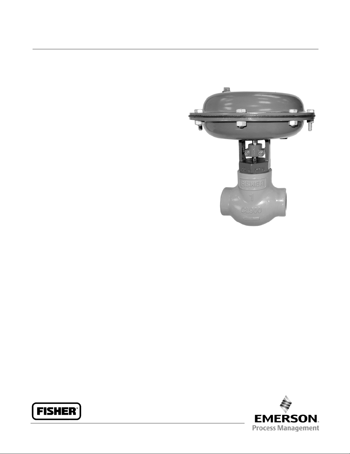
Fisherr D2 FloPro Control Valve
The Fisher D2 FloPro control valve is a compact,
rugged valve designed for on-off control. This valve is
ideal for use as a dump valve on gas separators and
scrubbers. It is also well suited for other high pressure
applications in natural gas production, compression,
and processing. The D2 FloPro valve has threaded end
connections and is available in an NPS 1 globe style
valve body.
Features
Field-Selectable Flow Rates–The FloPro feature
allows easy setting of 0.25, 0.375, and 0.5 inch flow
rates, eliminating the need for more than one port
size. See figure 2.
Product Bulletin
51.2:D2
June 2012
Trim Options–The valve plug and seat ring are
available in S17400 double H1150, or solid R30006
(Alloy 6) for erosive service.
ENVIRO-SEALt D2 Packing System–
The ENVIRO-SEAL D2 packing system provides an
improved stem seal to prevent the loss of valuable
or hazardous process fluids or gases. It features
live-loading, providing reduced packing
maintenance.
NACE MR0175/ISO 15156 Service- Ready–Sour
service trim is the standard construction for the D2
FloPro control valve. The materials of construction
meet the metalurgical requirements of NACE
MR0175/ISO 15156. Environmental limits may
apply.
CL900 Service–Valve assembly is designed and
specified for ASME B16.34 CL900 service.
Low Temperature Materials–Valve and actuator
construction materials allow use in low temperature
applications of -46 C.
W9235-1
Fisher D2 FloPro Control Valve
Field-Reversible Actuator–The D2 FloPro actuator
can be converted in the field from Air-to-Open to
Air-to-Close actuator action. (Conversion to
Air-to-Close actuator action requires removing four
springs from the actuator casing configuration.)
(Conversion to Air-to-Open actuator action requires
adding four springs to the actuator casing
configuration.)
Easy Installation–Compact design allows
installation where space is at a premium.
Easy Maintenance–Screwed bonnet/body joint
allows repair or maintenance with a minimum of
tools and without removing the valve body from the
piping system.
www.Fisher.com
Page 2

Product Bulletin
51.2:D2
June 2012
Specifications
D2 FloPro Valve
D102816X012
Valve Assembly Pressure Class
(1)
ASME B16.34 CL900
Temperature Range
(1)
155barfrom-46to93C, and 150 bar at 149C.
(2250 psig from —50 to 200F, and 2185 psig at
300F)
Maximum Allowable Pressure Drop
Flow Down
(2)
(1)
Maximum Inlet Pressure: 155bar(2250psig)
Maximum Outlet Pressure: 103 bar (1500 psig)
Flow Up
Maximum Inlet Pressure: 103bar(1500psig)
Maximum Outlet Pressure: 103 bar (1500 psig)
Shutoff Classification
Class IV ANSI/FCI 70-2 and IEC 60534-4
Construction Materials
Valve Body and Bonnet: ASME SA 352 LCC
Valve Plug and Seat:
J S17400 double H1150
J R30006 (Alloy 6) or
Valve Stem: S31600
O-Rings: HNBR (Hydrogenated Nitrile)
Packing: PTFE/Carbon PTFE
Packing Springs: N07718
Stem Bushing: PPS (polyphenylene sulfide)
Actuator Diaphragm: Nitrile/Polyester
Actuator Springs: Zinc-plated steel
Maximum Travel
13 mm (0.5 inch)
Valve Travel Indications
See figure 2
Approximate Weight
7.7 kg (17 lb)
Dimensions
See figure 3
Material Temperature Capabilities
Valve Body Assembly: -46 to 149C
(-50 to 300F)
Actuator Assembly: -46 to 93C(-50to200F)
Bonnet/Body Connection
Screwed with leakoff bleed
Standard Actuator Configuration
The D2 FloPro actuator is an on-off
spring-and-diaphragm.
Globe Valve Body: Supplied as either Air-to-Open or
Air-to-Close.
Maximum Actuator Casing Pressure
2.8bar(40psig)
Flow Characteristic
FloPro Characterized
Flow Coefficients
Seefigure2
Port Diameter
13 mm (0.5 inch)
1. The pressure or temperature limits in the referenced tables andany applicable ASME code limitations should not beexceeded.
2. Standard flow direction.
2
Minimum Required Actuator Casing Pressure
2.1 to 2.4 bar (30 to 35 psig)
Actuator Diaphragm Effective Area
194 cm
2
Actuator Pressure Connections
1/4 NPT internal; see figure 3 for locations
(30 square inches)
Page 3

D2 FloPro Valve
D102816X012
Figure 1. Fisher D2 FloPro Constructions
Product Bulletin
51.2:D2
June 2012
GE15452
GLOBE STYLE AIR-TO-OPEN
Figure 2. Flow Rate Adjustments
FloPro TRAVEL
INDICATOR
FLOW ADJUSTOR
1
SAFETY
VENT
2
3
GE15452
1
0.5 INCH FLOW RATE
Fl = 0.77
Xt = 0.476
Cv = 6
2
0.375 INCH FLOW RATE
Cv = 4
Fl = 0.706
Xt = 0.319
3
0.25 INCH FLOW RATE
Cv = 2
Fl = 0.65
Xt = 0.245
3
Page 4

Product Bulletin
51.2:D2
June 2012
Figure 3. Fisher D2 Globe Valve Dimensions (Air-to-Open Configuration Shown)
216
(8.50)
DIAMETER
1/4 NPT
VENT CONNECTION
76
(3.00)
D2 FloPro Valve
D102816X012
19B8490-B
E0783
194
(7.65)
43
(1.69)
51
(2.00)
DIAMETER
60
(2.35)
1/4 NPT
SUPPLY CONNECTION
1NPT
mm
(INCH)
120
(4.70)
Neither Emerson, Emerson Process Management, nor any of their affiliated entities assumes responsibility for the selection, use or maintenance
of any product. Responsibility for proper selection, use, and maintenance of any product remains solely with the purchaser and end user.
Fisher and ENVIRO-SEAL are marks owned by one of the companies in the Emerson Process Management business unit of Emerson Electric Co. Emerson
Process Management, Emerson, and the Emerson logo are trademarks and service marks of Emerson Electric Co. All other marks are the property oftheir
respective owners.
The contents of this publication are presented for informational purposes only, and while every effort has been made to ensure their accuracy, theyarenot
to be construed as warranties or guarantees, express or implied, regarding the products or services described herein or their use or applicability. All sales are
governed by our terms and conditions, which are available upon request.We reservethe rightto modifyor improvethe designs orspecifications of such
products at any time without notice.
Emerson ProcessManagement
Marshalltown, Iowa 50158 USA
Sorocaba, 18087 Brazil
Chatham, Kent ME4 4QZ UK
Dubai, United Arab Emirates
Singapore 128461 Singapore
www.Fisher.com
E 2001, 2012 Fisher Controls International LLC. All rights reserved.
4
 Loading...