

Page 1

Instruction Manual
D100386X012
Fisherr D and DA Valves
DandDAValves
June 2014
Contents
Introduction 1.................................
Scope of Manual 1.............................
Description 1.................................
Specifications 2...............................
Educational Services 2.........................
Ceramic Trim 3................................
Installation 3..................................
Maintenance 5.................................
Packing Lubrication 5..........................
Packing Maintenance 6.........................
Replacing Packing 6...........................
Trim Maintenance 8...........................
Disassembly 8.............................
Lapping Metal Seats 8......................
Assembly 9...............................
Parts Ordering 9................................
Parts Kits 10...................................
Parts List 10...................................
Figure 1. Fisher D Valve with 657 Actuator
W0232
Introduction
Scope of Manual
This instruction manual includes installation, maintenance, and parts information for Fisher D and DA valves. Refer to
separate manuals for instructions covering the actuator, positioner, and accessories.
Do not install, operate, or maintain a D or DA valve without being fully trained and qualified in valve, actuator, and
accessory installation, operation, and maintenance. To avoid personal injury or property damage, it is important to
carefully read, understand, and follow all the contents of this manual, including all safety cautions and warnings. If you
have any questions about these instructions, contact your Emerson Process Management sales office before
proceeding.
Unless otherwise noted, all NACE references are to NACE MR0175-2002.
Description
The D globe-style (figure 1) and DA angle-style (figure 5) valves are single-port, metal-seated valves for high-pressure
applications.
www.Fisher.com
Page 2
DandDAValves
June 2014
Table 1. Specifications
Instruction Manual
D100386X012
Maximum Inlet Pressures and Temperatures
(1)
If the valve nameplate shows an ASME
pressure-temperature class, maximum inlet pressure
and temperature is consistent with applicable ASME
class per ASME B16.34.
If the nameplate does not show an ASME class, it will
show a maximum cold working pressure at 38_C
(100_F) (for example, 3600, 6000, 9000, or 10,000
psi)
Maximum Allowable Pressure Drops
(1)
Flow up: Capable of full rated pressure drops
Flow down: See table 2 for pressure drop limits for
ceramic trim
Shutoff Classification Per ANSI/FCI 70-2
and IEC 60534-4
Standard: Class IV
Optional: Class V
1. Do not exceed thepressure or temperature limitsin this manual and any applicable standard limitations.
Maximum Service Temperature
232_C(450_F)
Flow Characteristic
Equal Percentage
Flow Direction
DValve:Flow up through the seat ring and out past
the valve plug
DA Valve: Flow in either direction
Approximate Weight
DValve:34 kg (75 lbs)
DA Valve: 46 kg (100 lbs)
Specifications
Specifications for these valves are in table 1. Some of the specifications for a given valve appear on a nameplate, which
is attached to the valve actuator or wired to the valve assembly if the valve was purchased without an actuator.
Educational Services
For information on available courses for Fisher D and DA valves, as well as a variety of other products, contact:
Emerson Process Management
Educational Services - Registration
Phone: 1-641-754-3771 or 1-800-338-8158
E-mail: education@emerson.com
http://www.emersonprocess.com/education
Table 2. Flow Down Pressure Drop Limits - Ceramic Trim Only
VALVE SIZE
NPS
1 414 414 414 193 --- ---
2 689 689 689 462 262 165
1 6000 6000 6000 2800 --- ---
2 10,000 10,000 10,000 6700 3800 2400
6.4 (0.25) 9.5 (0.375) 12.7 (0.5) 19.1 (0.75) 25.4 (1) 31.8 (1.25)
SEAT RING DIAMETER, mm (INCHES)
Pressure Drop, bar
Pressure Drop, psi
2
Page 3

Instruction Manual
D100386X012
DandDAValves
June 2014
Ceramic Trim
Some types of ceramic trim, including the VTC (very tough ceramic) variety, can create a spark under certain
circumstances. When the edge of a ceramic part is struck against a second ceramic part with enough force, a spark can
be created.
WARNING
Avoid personal injury and property damage from ignition of process fluid caused by sparks from ceramic trim.
Do not use ceramic trim where the process fluid is unstable or if it is an explosive mixture (such as ether and air).
Installation
WARNING
Always wear protective gloves, clothing, and eyewear when performing any installation operations to avoid personal
injury.
To avoid personal injury or property damage resulting from the sudden release of process pressure or bursting of parts, do
not install the valve assembly where service conditions could exceed the limits given in this manual or on the appropriate
nameplates. Use pressure-relieving devices as required by government or accepted industry codes and good engineering
practices.
Check with your process or safety engineer for any additional measures that must be taken to protect against process
media.
If installing into an existing application, also refer to the WARNING a t the beginning of the Maintenance section in this
instruction manual.
CAUTION
When ordered, the valve configuration and construction materials were selected to meet particular pressure, temperature,
pressure drop, and controlled fluid conditions. Some body/trim material combinations are limited in their pressure drop
and temperature ranges. Do not apply any other conditions to the valve without first contacting your Emerson Process
Management sales office.
1. Before installing the valve, inspect it to be certain that the valve body cavity is free of foreign material. Clean out all
pipelines to remove scale, welding slag, and other foreign materials.
2. Install the valve so that flow through the valve is in the direction shown by the arrow cast on the valve body. The
control valve assembly may be installed in any position unless limited by seismic considerations. However, the
normal method is with the actuator vertical above the valve. With some valves, the actuator may need support
when it is not vertical. For more information, consult your Emerson Process Management sales office.
3. Use accepted piping and welding practices when installing the valve in the line. For flanged valve bodies, use
suitable gaskets between the body flanges and pipeline flanges.
3
Page 4
DandDAValves
June 2014
Instruction Manual
D100386X012
CAUTION
Depending on valve body materials used, post-weld heat treating might be needed. If so, damage to internal elastomeric
and plastic parts, as well as internal metal parts is possible. Shrink-fit pieces and threaded connections may also loosen. In
general, if post-weld heat treating is needed, remove all trim parts. Contact your Emerson Process Management sales office
for additional information.
For screwed end connections, apply pipe compound to pipeline threads.
4. To allow continuous operation during inspection or maintenance, install a three-valve bypass around the control
valve assembly.
5. If you received the actuator and valve body shipped separately, refer to the appropriate actuator instruction manual
for the actuator mounting procedure.
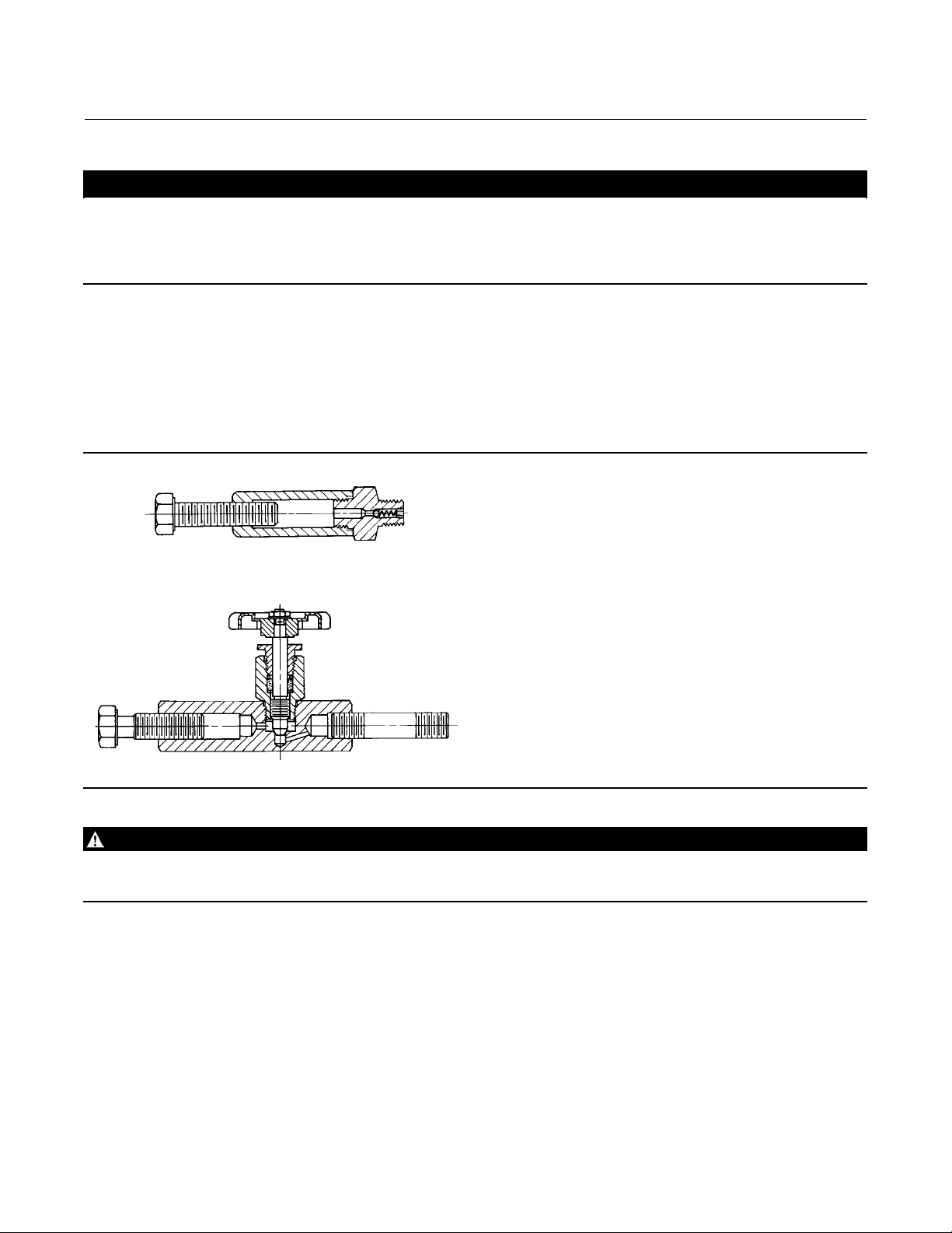
Figure 2. Lubricator and Lubricator/Isolating Valve (optional)
LUBRICATOR
10A9421-A
AJ5428-D
A0832-2
LUBRICATOR/ISOLATING VALVE
WARNING
Personal injury could result from packing leakage. Valve packing was tightened before shipment; however the packing
might require some readjustment to meet specific service conditions.
4
Page 5

Instruction Manual
D100386X012
DandDAValves
June 2014
Maintenance
WARNING
Avoid personal injury from sudden release of process pressure. Before performing any maintenance operations:
D Do not remove the actuator from the valve while the valve is still pressurized.
D Always wear protective gloves, clothing, and eyewear when performing any maintenance operations to avoid personal
injury.
D Disconnect any operating lines providing air pressure, electric power, or a control signal to the actuator. Be sure the
actuator cannot suddenly open or close the valve.
D Use bypass valves or completely shut off the process to isolate the valve from process pressure. Relieve process pressure
on both sides of the valve. Drain the process media from both sides of the valve.
D Vent the pneumatic actuator loading pressure and relieve any actuator spring precompression.
D Use lock-out procedures to be sure that the above measures stay in effect while you work on the equipment.
D The valve packing box may contain process fluids that are pressurized, even when the valve has been removed from the
pipeline. Process fluids may spray out under pressure when removing the packing hardware or packing rings, or when
loosening the packing box pipe plug.
D Check with your process or safety engineer for any additional measures that must be taken to protect against process
media.
Table 3. Bolting Torque for Packing Box Nuts (Key 15)
VALVE
RATING
3600 psi or to CL1500
6000 psi or CL2500
9000 psi
10,000 psi
STEM
DIAMETER
mm Inches NSm LbfSin NSm LbfSin
9.5
12.7
19.1
9.5
2.7
19.1
12.7
19.1
12.7
19.1
3/8
1/2
3/4
3/8
1/2
3/4
1/2
3/4
1/2
3/4
MINIMUM
RECOMMENDED TORQUE
4
7
16
5
9
20
6
20
6
20
36
66
144
42
78
180
54
180
54
180
MAXIMUM
RECOMMENDED TORQUE
5
11
24
7
12
30
8
30
8
30
48
96
216
60
108
264
72
264
72
264
Valve body parts are subject to normal wear and must be inspected and replaced as necessary. Inspection and
maintenance frequency depends on the severity of service conditions. This section includes instructions for packing
lubrication, packing maintenance, trim maintenance, and lapping seating surfaces. All maintenance operations can be
performed with the valve in the line.
Note
Whenever a gasket seal is disturbed by removing or shifting gasketed parts, install a new gasket upon reassembly. This is necessary
to ensure a good gasket seal because the used gasket might not seal properly.
Packing Lubrication
Thevalvemighthaveanoptionallubricatororlubricator/isolatingvalve(figure2)inthetappedbonnet.Usethe
lubricator or lubricator/isolating valve for PTFE/composition or o ther packings that need lubrication. Use a silicon-base
5
Page 6

DandDAValves
June 2014
lubricant. Do not lubricate packing used in oxygen service. To operate the lubricator, turn the cap screw clockwise to
force the lubricant into the packing box. The lubricator/isolating valve operates the same way except open the
isolating valve before turning the cap screw. Close the isolating valve after lubrication is completed.
Instruction Manual
D100386X012
Packing Maintenance
Refer to figures 3, 4, and 5 for key number locations. For spring-loaded single PTFE V-ring packing, the packing spring
(key 9) maintains a sealing force on the packing. If you find leakage around the packing follower (key 10), check to be
sure the packing follower is touching the bonnet (key 5). If the packing follower is not touching the bonnet, tighten
the packing flange nuts (key 15) until the packing follower touches the bonnet. If you cannot stop leakage in this way,
proceed to the Replacing Packing procedure.
If there is unwanted packing leakage with other than spring-loaded packing, first try to limit the leakage and seal the
stem. To limit the leakage, tighten the packing flange nuts (key 15) to at least the minimum recommended torque in
table 3. However, do not exceed the maximum recommended torque in table 3, or excessive friction might result. If
the packing (key 8) is relatively new and tight on the stem, and tightening the packing flange nuts does not stop the
leakage, a worn or nicked valve stem might prevent a seal. If the leakage comes from the outside diameter of the
packing, nicks or scratches around the packing box wall might cause the leakage. While replacing the packing per the
numbered steps below, inspect the valve stem and packing box wall for nicks and scratches.
Replacing Packing
Except where indicated, refer to figures3,4,and5forkeynumberlocations.
WARNING
Refer to the WARNING at the beginning of the Maintenance section in this instruction manual.
1. Isolatethecontrolvalvefromthelinepressure,releasepressure from both sides of the valve body, and drain the
process media from both sides of the valve. If using a power actuator, also shut-off all pressure lines to the power
actuator and any leak-off piping from the bonnet. Release all pressure from the actuator and relieve spring
precompression. Use lock-out procedures to be sure that the above measures stay in effect while you work on the
equipment.
Disconnect the stem connector, and then remove the actuator from the valve body by unscrewing the actuator yoke
locknut (key 14).
2. Loosen the packing flange nuts (key 15) so the packing is not tight on the valve stem. Remove any travel indicator
parts and stem locknuts from the valve stem threads.
3. Unscrew the bonnet (key 5) from the valve body (key 1). Carefully lift off the bonnet and valve plug/stem assembly
(key 4) as a unit. Set the bonnet on a protective surface to prevent damage to the bonnet threads and gasket
surface.
4. Removethevalveplug/stemassemblyfromthebonnet.Ifyouplantore-usethevalveplug,tapeorotherwise
protect the valve plug seating surface and the stem threads to prevent damage.
5. Remove the bonnet gasket (key 7). Cover the opening in the valve body to protect the gasket surface and prevent
foreign material from getting into the body cavity.
6. Remove the packing flange nuts, packing flange, upper wiper, and follower (keys 15, 12, 21, and 10). Carefully push
out all the remaining packing box parts from the bonnet using a rounded rod or other tool that will not scratch the
packing box wall or bottom guide bushing. Clean the packing box and the metal packing box parts.
7. Inspect the valve stem threads and packing box surfaces for any sharp edges that might cut the packing. Scratches
or burrs could cause packing box leakage or damage to the new packing. If you cannot improve the surface
condition by light sanding, replace the damaged parts.
6
Page 7

Instruction Manual
D100386X012
Figure 3. Packing Arrangements
DandDAValves
June 2014
C0755-1
9.5mm(3/8INCH)STEM
9.5 mm
(3/8 INCH)
STEM
12.7 mm (1/2 INCH) STEM
12.7 mm
(1/2 INCH)
STEM
19.1 mm
(3/4 INCH)
STEM
8. Install a new bonnet gasket (key 7), making sure the gasket seating surfaces are clean and smooth. Carefully install
the valve plug/stem assembly into the valve body. Then slide the bonnet over the stem and thread it tightly into the
valve body, per the torque values in table 4.
9. Install new packing and the metal packing box parts according to the correct arrangement in figure 3. Place a
smooth-edged pipe over the valve stem, and gently tap each soft packing part into the packing box.
Table 4. Torque for Body-to-Bonnet Joint
VALVE SIZE
NPS 1 1060 780
NPS 2 - Up to 6000 psi valve rating 2030 1500
NPS 2 - 9000
1. 9000 psi valve rating is available for DA only.
(1)
and 10,000 psi valve rating 2710 2000
NSm
RECOMMENDED TORQUE
LbfSft
7
Page 8

DandDAValves
June 2014
Instruction Manual
D100386X012
Table 5. Torque for Seat Ring (Key 2)
VALVE SIZE, NPS
1 407 300
2 698 515
NSm LbfSft
RECOMMENDED TORQUE
10. Slide the packing follower, upper wiper, and packing flange (keys 10, 21, and 12) into position. Lubricate the
packingflangestuds(key13)andthefacesofthepackingflange nuts (key 15). Install the packing flange nuts.
11. For spring-loaded PTFE V-ring packing, tighten the packing flange nuts (key 15) until the packing follower (key 10)
contacts the bonnet. For other packing arrangements, tighten the packing flange nuts (key 15) alternately in small
equal increments. Continue until one of the nuts reaches the minimum recommended torque shown in table 3.
Then tighten the remaining packing flange nut until the packing flange is level and at a 90-degree angle to the valve
stem.
12. Mount the actuator on the bonnet (key 5) and connect the actuator and valve plug stem according to the
procedure in the appropriate actuator instruction manual.Checkforleakagearoundthe packing follower when you
put the control valve assembly into service. Retighten the packing flange nuts as required.
Trim Maintenance
Refer to figure 4 and 5 for key number locations.
Disassembly
1. Remove the actuator and the bonnet as described in steps 1 through 3 of the Replacing Packing procedure.
CAUTION
Use care to avoid damaging the gasket sealing surfaces.
The stem surface finish of the valve plug/stem assembly (key 4) is critical for making a good packing seal. The seating
surfaces of the seat ring (key 2) and the plug of the valve plug/stem assembly (key 4) are critical for tight shutoff. Protect
these parts from damage if you plan to re-use them in the valve.
2. If you wish, remove the valve plug/stem assembly (key 4)andthepackingpartsfromthebonnet.Ifyouplanto
re-usethevalveplug,tapeorotherwiseprotectthevalveplugseatingsurfaceandthestemthreadstoprevent
damage. Remove the packing parts as described in the Packing Maintenance procedure.
3. Use a socket wrench to remove the seat ring (key 2).
4. Remove the seat ring (key 2) and seat ring gasket (key 3) from the valve body.
5. Inspect parts for wear or damage that would prevent proper operation of the valve body. Clean the gasket surfaces.
6. Replace trim parts as necessary or use the Lapping Metal Seats procedure.
Lapping Metal Seats
A certain amount of leakage should be expected with metal-to-metal seating in any valve body. If the leakage
becomes excessive, however, the condition of the seating surfaces of the valve plug and seat ring (keys 4 and 2, figures
4 and 5) can be improved by lapping. (Deep nicks should be machined out rather than ground out.) Use a good quality
lapping compound of a mixture of 280 to 600-grit. Apply the compound to the bottom of the valve plug.
Partially assemble the valve so the seat ring and valve plug are in place and the bonnet (with bushing installed) is
screwed hand-tight into the body. Make a simple handle from a piece of strap iron locked to the valve plug stem with
8
Page 9

Instruction Manual
D100386X012
nuts. Rotate the handle alternately in each direction with light downward pressure to lap the seats. If you think there is
not enough lubrication (for example, if you hear a squeaking noise or feel vibration), stop the procedure, and apply
more lapping compound before continuing. After lapping, remove the bonnet and valve plug/stem assembly as a unit,
and clean the seating surfaces. Completely assemble as described in the Assembly portion of the Trim Maintenance
procedure.
Testthevalveforshutoff.Repeatthelappingprocedureifleakageisstillexcessive.
DandDAValves
June 2014
Assembly
1. Thoroughly clean the seat ring and bonnet threads in the valve body (key 1). Also clean the valve body seat ring
gasket surfaces.
2. Apply anti-seize lubricant to the threads of the seat ring (key 2), bonnet (key 5), and their mating threads in the
body.
3. Put the seat ring gasket (key 3) into the body.
4. Screw the seat ring into the body. Use a socket wrench to tighten the seat ring to the torque values shown in table
4. Remove all excess lubricant after tightening.
5. Clean the bonnet gasket seating surfaces, and install a new bonnet gasket (key 7).
6. If you had not removed the valve plug/stem assembly and packing from the bonnet, then install the bonnet (key 5)
and valve plug/stem assembly (key 4) as a unit, into the valve body. Keeping the valve plug/stem assembly in an
“up” position, thread the bonnet tightly into the valve body, per torque values in table 4.
7. If you had previously chosen to remove the valve plug/stem assembly and packing from the bonnet, then remove
any protective tape or covering from the valve plug/stem assembly (key 4) and carefully install it into the valve
body. Slide the bonnet (key 5) over the stem and thread it tightly into the valve body. Install new packing and the
metal packing box parts according to the correct arrangement in figure 3. Place a smooth-edged pipe over the valve
stem, and gently tap each soft packing part into the packing box.
8. Slide the packing follower, upper wiper, and packing flange (keys 10, 21, and 12) into position. Lubricate the
packing flange studs (key 13) and the washer surfaces of the packing flange nuts (key 15). Install the packing flange
nuts.
9. For spring-loaded PTFE V-ring packing, tighten the packing flange nuts (key 15) until the packing follower (key 10)
contacts the bonnet. For other packing arrangements, tighten the packing flange nuts (key 15) alternately in small
equal increments. Continue until one of the nuts reaches the minimum recommended torque shown in table 3.
Then tighten the remaining packing flange nut until the packing flange is level and at a 90-degree angle to the valve
stem.
10. Mount the actuator on the bonnet (key 5) and connect the actuator and valve plug stem according to the
procedure in the appropriate actuator instruction manual. Check for leakage around the packing follower (key 10)
when you put the control valve assembly into service. Retighten the packing flange nuts as required.
Parts Ordering
Each body-bonnet assembly is assigned a serial number, which is on the body or nameplate. The serial number also
appears on the actuator nameplate if you bought a valve and actuator assembly. Refer to this serial number when
contacting your Emerson Process Management sales office for technical advice. When ordering replacement parts,
mention the serial number. Also specify key number, part description, material, and part number from the following
lists of Parts Kits and part numbers.
WARNING
Use only genuine Fisher replacement parts. Components that are not supplied by Emerson Process Management should
not, under any circumstances, be used in any Fisher valve, because they may void your warranty, might adversely affect the
performance of the valve, and could cause personal injury and property damage.
9
Page 10

DandDAValves
June 2014
Instruction Manual
D100386X012
Parts Kits
Key Description Part Number
- - - Packing Box Parts for Double PTFE V-Ring
Packing (Includes keys 3, 7, 8, 11, 18, 19, and 21)
9.5 mm (3/8 Inch) Stem RDX0000CN12
12.7 mm (1/2 Inch) Stem RDX0000CN22
- - - Trim Package (S31600)
[Includes Equal Percentage S31600 (316 SST) W/R30006 (alloy6)
tip valveplug/stem (key4), S316000 w/alloy 6 seat ring (key 2),
stainless steel gaskets (keys 3 & 7), and single PTFE packing parts
(keys 8, 9, 11, 17, 18, and 21) or double PTFE packing p arts (keys
8, 11, 18, 19, and 21)]
Double PTFE V-Ring Packing
NPS1Valvew/9.5mm(3/8Inch)StemDia.
6.4 mm (0.25 Inch) port dia. RDXCNTRM112
9.5 mm (0.375 Inch) port dia. RDXCNTRM122
12.7 mm (0.5 Inch) port dia. RDXCNTRM132
19.1 mm (0.75 Inch) port dia. RDXCNTRM142
NPS2Valvew/12.7mm(1/2Inch)StemDia.
6.4 mm (0.25 Inch) port dia. RDXCNTRM212
9.5 mm (0.375 Inch) port dia. RDXCNTRM222
12.7 mm (0.5 Inch) port dia. RDXCNTRM232
19.1 mm (0.75 Inch) port dia. RDXCNTRM242
25.4 mm (1-Inch) port dia. RDXCNTRM252
31.8 mm (1.25 Inch) port dia. RDXCNTRM262
- - - Trim Package (Ceramic)
Includes seat ring and valve plug/stemassy (keys 2 and 4)
NPS1Valvew/9.5mm(3/8Inch)StemDia.
6.4 mm (0.25 Inch) port dia. RDXVTC00012
9.5 mm (0.375 Inch) port dia. RDXVTC00022
12.7 mm (0.5 Inch) port dia. RDXVTC00032
19.1 mm (0.75 Inch) port dia. RDXVTC00042
NPS2Valvew/12.7mm(1/2Inch)StemDia.
6.4 mm (0.25 Inch) port dia. RDXVTC00052
9.5 mm (0.375 Inch) port dia. RDXVTC00062
12.7 mm (0.5 Inch) port dia. RDXVTC00072
19.1 mm (0.75 Inch) port dia. RDXVTC00082
25.4 mm (1-Inch) port dia. RDXVTC00092
31.8 mm (1.25 Inch) port dia. RDXVTC00102
Parts List
Note
Part numbers are shown for recommended spares only. For part
numbers not shown, contact your Emerson Process Management sales
office.
Note
Abbreviations used in this parts list are: SST (stainless steel), RTJ
(ring-type joint), RF (raised face), SCH(schedule), BWE (buttwelding
end), dia. (diameter), in. (inches), mm (millimeters), psi (pounds per
square inch), and zn pl (zinc plated).
Sizes shown in inches are valve sizes unless otherwise stated.
Select parts titled 3600 PSI if your valve has a CL1500 or lower rating and
select parts titled 6000 PSI if your valve has a CL2500 rating.
Key Description Part Number
001 ValveBody
If you need a valve body as a replacement part, order by valve
size, serial number, and desired material.
002* Seat Ring
CF8M or S31600 (316 SST) w/COCR-A seat
NPS 1 valve
6.4 mm (0.25 inch) port dia. 2B5097X0012
9.5 mm (0.375 inch) port dia. 2B5098X0012
12.7 mm (0.5 inch) port dia. 2B5099X0012
19.1 mm (0.75 inch) port dia. 2B5100X0012
NPS 2 valve
6.4 mm (0.25 inch) port dia. 2B5106X0012
9.5 mm (0.375 inch) port dia. 2B5107X0012
12.7 mm (0.5 inch) port dia. 2B5108X0012
19.1 mm (0.75 inch) port dia. 2B5109X0012
25.4 mm (1-inch) port dia. 2B5110X0012
31.8 mm (1.25 inch) port dia. 2K1801X0012
316 SST w/tungsten carbide insert
NPS 1 valve
6.4 mm (0.25 inch) port dia. 1J6886000A2
9.5 mm (0.375 inch) port dia. 1J6887000A2
12.7 mm (0.5 inch) port dia. 1J6888000A2
19.1 mm (0.75 inch) port dia. 1J6889000A2
NPS 2 valve
6.4 mm (0.25 inch) port dia. 1J6899000A2
9.5 mm (0.375 inch) port dia. 1J8154000A2
12.7 mm (0.5 inch) port dia. 1J8156000A2
25.4 mm (1-inch) port dia. 1J8160000A2
Ceramic
NPS 1 valve
6.4 mm (0.25 inch) port dia. 22B8996X012
9.5 mm (0.375 inch) port dia. 22B8997X012
12.7 mm (0.5 inch) port dia. 22B8998X012
19.1 mm (0.75 inch) port dia. 22B8999X012
NPS 2 valve
6.4 mm (0.25 inch) port dia. 22B9000X012
9.5 mm (0.375 inch) port dia. 22B9001X012
12.7 mm (0.5 inch) port dia. 22B9002X012
19.1 mm (0.75 inch) port dia. 22B9003X012
25.4 mm (1-inch) port dia. 22B9004X012
31.8 mm (1.25 inch) port dia. 22B9005X012
10
*Recommended spare parts
Page 11

Instruction Manual
D100386X012
DandDAValves
June 2014
Key Description Part Number
003* Gasket
S31600 (316 SST)
For NPS 1 valves and NACE MR0175-2002
For NPS 2 valves and NACE MR0175-2002
004* Micro-Flute valve plug/stem assembly
NACE MR0175-2002
(1)
S31600, COCR-Aseat - S20910
(1)
(1)
1B198636042
1B198836042
NPS 1 valve, 9.5 mm (3/8 in.)stem
1flute
6.4 mm (0.25 inch) port dia. 2N7147X0032
3flutes
6.4 mm (0.25 inch) port dia. 2F3280X0022
9.5 mm (0.375 inch) port dia. 2N7389X0022
12.7 mm (0.5 inch) port dia. 2N7338X0022
19.1 mm (0.75 inch) port dia. 2N7393X0022
004* Equal percentage valve plug/stem assembly
S31600 (316 SST) w/S20910 (22-13-5) & Alloy 6 for
NACE MR0175-2002
(1)
NPS 1 valve, 9.5 mm (3/8 in.)stem
6.4 mm (0.25 inch) port dia. 2F1388X0042
9.5 mm (0.375 inch) port dia. 2F1389X0032
12.7 mm (0.5 inch) port dia. 2F1390X0032
19.1 mm (0.75 inch) port dia. 2F1391X0032
NPS 2 valve, 12.7 mm (1/2 in.)stem
6.4 mm (0.25 inch) port dia. 2F1427X0022
9.5 mm (0.375 inch) port dia. 2F1428X0022
12.7 mm (0.5 inch) port dia. 2F1429X0022
19.1 mm (0.75 inch) port dia. 2F1430X0022
25.4 mm (1-inch) port dia. 2F1431X0022
31.8 mm (1.25 inch) port dia. 2L5331X0032
S31600 (316 SST) w/tungstencarbide tip for NACE
MR0175-2002
(1)
NPS 1 valve, 9.5 mm (3/8 in.)stem
6.4 mm (0.25 inch) port dia. 2J6894X0022
9.5 mm (0.375 inch) port dia. 2J6895X0022
12.7 mm (0.5 inch) port dia. 2J6896X0022
19.1 mm (0.75 inch) port dia. 2J6897X0022
NPS 2 valve, 12.7 mm (1/2 in.)stem
6.4 mm (0.25 inch) port dia. 2J8189X0022
9.5 mm (0.375 inch) port dia. 2J8191X0022
12.7 mm (0.5 inch) port dia. 2J8193X0022
19.1 mm (0.75 inch) port dia. 2J8195X0022
25.4 mm (1-inch) port dia. 2J8197X0052
31.8 mm (1.25 inch) port dia. 2V2234X0022
Ceramic
NPS 1 valve, 9.5 mm (3/8 in)stem
6.4 mm (0.25 inch) port dia. 22B8956X012
9.5 mm (0.375 inch) port dia. 22B8957X012
12.7 mm (0.5 inch) port dia. 22B8958X012
19.1 mm (0.75 inch) port dia. 22B8959X012
NPS 1 valve, 12.7 mm (1/2 inch) stem
6.4 mm (0.25 inch) port dia. 22B8960X012
9.5 mm (0.375 inch) port dia. 22B8961X012
12.7 mm (0.5 inch) port dia. 22B8962X012
19.1 mm (0.75 inch) port dia. 22B8963X012
NPS 1 valve, 19.1 mm (3/4 in)stem
6.4 mm (0.25 inch) port dia. 22B8964X012
9.5 mm (0.375 inch) port dia. 22B8965X012
Key Description Part Number
12.7 mm (0.5 inch) port dia. 22B8966X012
19.1 mm (0.75 inch) port dia. 22B8967X012
NPS 2 valve, 12.7 mm (1/2 in) stem
6.4 mm (0.25 inch) port dia. 22B8968X012
9.5 mm (0.375 inch) port dia. 22B8969X012
12.7 mm (0.5 inch) port dia. 22B8970X012
19.1 mm (0.75 inch) port dia. 22B8971X012
25.4 mm (1-inch) port dia. 22B8972X012
31.8 mm (1.25 inch) port dia. 22B8973X012
NPS 2 valve, 19.1 mm (3/4 inch) stem
6.4 mm (0.25 inch) port dia. 22B8974X012
9.5 mm (0.375 inch) port dia. 22B8975X012
12.7 mm (0.5 inch) port dia. 22B8976X012
19.1 mm (0.75 inch) port dia. 22B8977X012
25.4 mm (1-inch) port dia. 22B8978X012
31.8 mm (1.25 inch) port dia. 22B8979X012
005 Bonnet/Bushing Assy
If you need a bonnet as a replacement part, order by valve size
and stem diameter, serial number, and desired material.
007* Gasket
S31600 (316 SST)
For NPS 1 valves and NACE MR0175-2002
For NPS 2 valves and NACE MR0175-2002
(1)
(1)
1B198236042
1B198436042
008* Packing Ring
Double PTFE/Composition packing
9.5 mm (3/8 in.) stem (7 req'd) 1F3370X0012
12.7 mm (1/2 in.) stem (10 req'd) 1E319001042
19.1 mm (3/4 in.) stem (8 req'd) 1E319101042
Double PTFE V-Ring
9.5 mm (3/8 in.) stem (6 req'd) 1C752601012
12.7 mm (1/2 in.) stem (6 req'd) 1C752701012
19.1 mm (3/4 in.) stem (6 req'd) 1C752801012
010 Packing Follower
011* Packing Adaptor, male
Double PTFE V-Ring packing
9.5 mm (3/8 in.) stem (2 req'd) 1F124801012
12.7 mm (1/2 in.) stem (2 req'd) 1F124701012
19.1 mm (3/4 in.) stem (2 req'd) 1F124601012
012 Packing Flange
013 Packing Box Stud
014 Yoke Locknut, steel
015 Hex Nut
016 Pipe Plug
016 Stem Lubricator/Isolating Valve
016 Pipe Nipple, for lubricator/isolating valve
016 Stem Lubricator
018* Packing Adaptor, female
Double PTFE V-Ring
9.5 mm (3/8 in.) stem (2 req'd) 1F124401012
12.7 mm (1/2 in.) stem (2 req'd) 1F124301022
19.1 mm (3/4 in.) stem (2 req'd) 1F124201012
019 Lantern Ring
021* Upper Wiper,felt
9.5 mm (3/8 in.) stem 1J872606332
12.7 mm (1/2 in.) stem 1J872706332
19.1 mm (3/4 in.) stem 1J872806332
025 Seal & Wire (not shown), lead
Required only if actuator is not furnished
--- Tag,warning(notshown)
*Recommended spare parts
1. These materials are listed in NACE standardMR0175-2002 as being acceptable for
direct exposure to sour environmentwhen used under conditions stated in that
standard.
11
Page 12

DandDAValves
June 2014
Instruction Manual
D100386X012
Figure 4. Fisher D Globe-Style Valve
Figure 5. Fisher DA Angle-Style Valve
NOTE:
PIPE PLUG (KEY 16) INCLUDED
NOTE:
PIPE PLUG (KEY 16) INCLUDED ONLY IF BONNET IS DRILLED AND TAPPED
FOR PACKING LUBRICATORAND LUBRICATOR IS NOT INSTALLED.
BF2007-F
A5862-1
ONLY IF BONNET IS DRILLED AND
TAPPED FOR PACKING LUBRICA
TOR AND LUBRICATORIS NOT
INSTALLED.
BF2035-D
A5861-1
Neither Emerson, Emerson Process Management, nor any of their affiliated entities assumes responsibility for the selection, use or maintenance
of any product. Responsibility for proper selection, use, and maintenance of any product remainssolely with the purchaser and end user.
Fisher is a mark owned by one of the companies in theEmerson Process Management business unit of Emerson Electric Co. Emerson Process Management,
Emerson, and the Emerson logo are trademarks and service marks of Emerson Electric Co. All other marks are the property of their respective owners.
The contents of this publication are presented for informational purposes only, and while every effort has been made to ensure their accuracy, they arenot
to be construed as warranties or guarantees, express or implied, regarding the products or services described herein or their use or applicability. All sales are
governed by our t erms and conditions, which are available upon request. We reserve the right to modify or improve the designs or specifications of such
products at any time without notice.
Emerson Process Management
Marshalltown, Iowa 50158 USA
Sorocaba, 18087 Brazil
Chatham, Kent ME4 4QZ UK
Dubai, United Arab Emirates
Singapore 128461 Singapore
www.Fisher.com
12
E 1991, 2014 Fisher Controls International LLC. All rights reserved.
 Loading...