

Page 1
DandDAValves
D100039X012
Fisherr D and DA Control Valves
Fisher D and DA single-port, high-pressure valves are
widely used in oil and gas production industries. These
valves are especially useful for either throttling or
on/off control of liquids or gases which are gritty,
sticky, or which have a tendency to build up on internal
valve parts. The DA valve is also useful in angle piping
or other applications where a self-draining valve is
desired.
Unless otherwise noted, all NACE references are to
NACE MR0175-2002.
Features
Heavy-Duty Construction–Massive guiding (figure
1) positively aligns the valve plug in the seat ring for
high pressure drop applications. The screwed-in
seat ring completely encloses the seat ring gasket.
Product Bulletin
51.2:D
March 2014
Easy Maintenance–Screwed bonnet/body joint
allows repair or maintenance with a minimum of
tools.
Severe Service Capability–Valve is available with
VTC (ceramic) trim for service in very erosive
applications. The valve plug is also available with a
tungsten carbide tip and the seat ring can be fitted
with a full-bore tungsten carbide insert for erosive
service.
Meets Variety of Specifications–Valve body and end
connection constructions are available for API as
well as ASME standards.
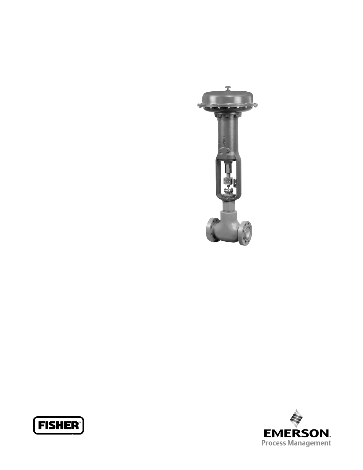
W7859-1
Fisher D Valve with 657 Actuator
NACE Trim Standard–NACE trim and bolting
materials are standard for all applications. These
materials comply with the requirements of NACE
MR0175-2002.
www.Fisher.com
Page 2

Product Bulletin
51.2:D
March 2014
Specifications
DandDAValves
D100039X012
Available Configurations
D: Globe valve with screwed-on bonnet, unbalanced
post-guided valve plug, screwed-in seat ring, metal
seat construction, and push-down-to-close valve plug
action
DA: Same as D valve except in angle configuration
(figure 1)
Valve Sizes and End Connections
(1)
See table 1
Maximum Inlet Pressures and Temperatures
(1)(2)
See table 2
Maximum Allowable Pressure Drops
(2)
Flow up: Capable of full rated pressure drops
Flow down: See table 3 for pressure drop limits for
ceramic trim
Shutoff Classification per ANSI/FCI 70-2
and IEC 60534-4
Standard: Class IV leakage
Optional: Class V
Flow Characteristic
Equal percentage
Flow Direction (see figure 1)
D: Flow up (through seat ring and past valve plug)
DA:
J Flow up (through seat ring and past valve plug)
or
J flow down (past valve plug and through seat
ring)
Flow Coefficients and Noise Level Prediction
See table 5 or Fisher Catalog 12
Port, Yoke Boss, Stem Diameters, and Rated Travels
See table 6
Approximate Weights
Material Temperature Capabilities
-46 to 232_C(-50to450_F)
NPS 1: 34 kg (75 pounds)
NPS 2: 45 kg (100 pounds)
Construction Materials
Body, Bonnet, and Trim: See table 4
Options
Packing:
Standard:
for pressure service
Optional: Double PTFE/Composition
Standard Gaskets: S31600 (316 SST)
1. EN (or other) ratings and end connections can usually besupplied; consult your Emerson Process Management sales office.
2. The pressure/temperaturelimits in this bulletin and in any applicable standard limitations shouldnot be exceeded.
J Single or J double PTFE V-ring packing
J Lubricator/isolating valve J VTC (ceramic) Trim
with equal percentage characteristic (not available
with Micro-Flute trim)
available with Micro-Flute trim)
Contents
Features 1.....................................
Specifications 2................................
Tables
Valve Sizes, Port Diameters, and End Connections 3.
Rated Inlet Pressures and Temperatures 3.........
Flow Down Pressure Drop Limits-
Ceramic Trim Only 3........................
Materials for Standard Trim Constructions 3.......
Flow Coefficient
(C
at Maximum Valve Plug Travel) 4...........
v
Port, Yoke Boss, Stem Diameters,
and Rated Travel Specifications 4..............
Installation 5..................................
Ordering Information 5..........................
Dimensions 6..................................
J Tungsten Carbide trim (not
2
Page 3
DandDAValves
D100039X012
Table 1. Valve Sizes, Port Diameters, and End Connections
SCREWED VALVE BODIES FLANGED VALVE BODIES
VALVE
SIZE,
NPS
1. `X' indicatesavailable construction.
PORT DIA METER
(INCHES)
0.25, 0.375,0.5,
1
2
0.75
0.25, 0.375,0.5,
0.75, 1, 1.25
3600 psi 6000 psi
(1)
X
X X X X X X X X
X --- --- X X X ---
9000 psi
(WCC Steel
DA Only)
10,000 psi
(Except WCC
Steel DA)
CL150
through
CL600
Product Bulletin
ASME API
CL900 and
CL1500
CL2500
51.2:D
March 2014
10,000 lb.
Spec A and C
Table 2. Rated Inlet Pressures and Temperatures
VALVE SIZE,
NPS
1or2 Screwed
1or2 Flanged
1. LCC steel body per ASME B16.34 exceptC5 steel for all API bodies.
TYPE
PRESSURE RATING OR COLD
WORKING PRESSURE LIMIT
CL900 and 1500
CL2500
9000 621 9000 38 100
10,000 689 10,000 38 100
CL150
CL300
CL600
CL900 and 1500
CL2500
API 10,000
Table 3. Flow Down Pressure Drop Limits - Ceramic Trim Only
VALVE SIZE,
NPS
1 414 414 414 193 --- ---
2 689 689 689 462 262 165
1 6000 6000 6000 2800 --- ---
2 10,000 10,000 10,000 6700 3800 2400
6.4 (0.25) 9.5 (0.375) 12.7 (0.5) 19.1 (0.75) 25.4 (1) 31.8 (1.25)
SEAT RINGDIAMETER, mm (INCHES)
bar psi _C _F
259
236
431
394
20.0
12.8
51.7
47.2
103.4
94.5
259
236
431
394
689
689
Pressure Drop, bar
Pressure Drop, psi
PRESSURE
Spec A 10,000
Spec C 10,000
(1)
3750
3425
6250
5710
290
185
750
685
1500
1370
3750
3425
6250
5710
TEMPERATURE
38
232
38
232
38
232
38
232
38
232
38
232
38
232
121
121
100
450
100
450
100
450
100
450
100
450
100
450
100
450
250
250
Table 4. Materials for Standard Trim Constructions
VALVE MATERIAL BONNETMATERIAL PLUG AND SEAT RING VALVE STEM
LCC
WCC
LF2
S31600 (316stainless steel)
hard faced with CoCr-A (Alloy 6)
S20910
3
Page 4

Product Bulletin
51.2:D
March 2014
Table 5. Flow Coefficient (Cvat Maximum Valve Plug Travel)
VALVE SIZE,
NPS
1
2
PORT DIAMETER,
mm (INCHES)
6.4 (0.25)
9.5 (0.375)
12.7 (0.5)
19.1 (0.75)
6.4 (0.25)
9.5 (0.375)
12.7 (0.5)
19.1 (0.75)
25.4 (1)
31.8 (1.25)
Table 6. Port, Yoke Boss, Stem Diameters, and Rated Travel Specifications in mm (Inches)
VALVE
SIZE,
NPS
1
2
PORT
DIAMETER
6.4 (0.25)
9.5 (0.375)
12.7 (0.5)
19.1 (0.75)
6.4 (0.25)
9.5 (0.375)
12.7 (0.5)
19.1 (0.75)
25.4 (1)
31.8 (1.25)
Yoke Boss
Diameter
54 (2-1/8) 9.5 (3/8) 19.1 (0.75)
71 (2-13/16) 12.7 (1/2) 19.1 (0.75) 90 (3-9/16) 19.1 (3/4) 19.1 (0.75)
STANDARD OPTIONAL
Diameter
EQUAL PERCENTAGE D EQUAL PERCENTAGE DA
Flow Up Flow Down
1.66
4.03
6.51
12.3
1.66
4.03
6.82
14.1
23.7
34.5
Stem
Rated
Travel
Yoke Boss
Diameter
71 (2-13/16) 12.7 (1/2) 19.1 (0.75)
90 (3-9/16) 19.1 (3/4) 19.1 (0.75)
DandDAValves
D100039X012
3.21
7.06
11.2
16.8
3.21
7.06
12.1
21.2
31.8
44.9
Stem
Diameter
Rated
Travel
Figure 1. Typical Constructions
W0540-2
W0938-2
4
Page 5

DandDAValves
D100039X012
Product Bulletin
51.2:D
March 2014
Installation
Valve orientation of the D and DA does not affect
operation, but to facilitate changing trim parts, the
valvestemshouldbeverticalwiththeactuatorabove
the valve. Proper flow direction is indicated by the
arrow on the valve.
Dimensions are shown in figures 2 and 3.
Ordering Information
When ordering, specify:
Application
1. Type of application
a. Throttling or on-off
b. Reducing or relief
2. Controlled fluid (include chemical analysis of fluid, if
possible)
6. Pressure drops
a. Range of flowing pressure drops
b. Maximum at shutoff
7. Flow rates
a. Minimum controlled flow
b. Normal flow
c. Maximum flow
8. Maximum permissible noise level, if critical
9. Shutoff classification required
10. Linesizeandschedule
Valve
Refer to the specifications. Review the description for
each specification. Indicate the desired choice
whenever there is a selection (
indicate the valve body design being ordered as
identified in the available configuration specification.
J)tobemade.Always
3. Specific gravity of controlled fluid
4. Fluid temperature
5. Range of flowing inlet pressure
Actuator and Accessories
Refer to separate bulletins covering actuators and
accessories for ordering information.
5
Page 6

Product Bulletin
51.2:D
March 2014
Table 7. Fisher D Dimensions
A
Ring-Type
Joint
ASME
A
G
Raised
Face
Ring-Type
Joint
Inches
mm
G
9.5
(3/8)
FLANGED
VALVE
SIZE,
NPS
1 206 46 219 232 46 232 232 46 173 192 179
2 267 70 267 --- 70 286 289 70 --- 217 213
1 8.12 1.81 8.62 9.12 1.81 9.12 9.12 1.81 6.81 7.56 7.06
2 10.50 2.75 10.50 --- 2.75 11.25 11.38 2.75 --- 8.56 8.38
CL150 CL300 CL600
A-Raised
Face
G
Raised
Face
Table 8. Fisher D Dimensions
FLANGED
VALVE
SIZE,
NPS
1 254 254 46 308 308 54 --- --- --- 173 192 179
2 308 311 70 391 394 83 364 360 83 --- 217 213
1 10.00 10.00 1.81 12.12 12.12 2.12 --- --- --- 6.81
2 12.12 12.25 2.75 15.38 15.50 3.25 14.34 14.19 3.25 --- 8.56 8.38
1. Not applicablefor 10,000 lb.API.
CL900 and 1500 CL2500 10,000 lb.
A
Raised
Face
Ring-Type
Joint
ASME API
A
G
Raised
Face
Ring-Type
Joint
G
mm
Inches
A
Spec A Spec C
G
DandDAValves
D100039X012
D--All Ratings
Stem Size
12.7
(1/2)
D--All Ratings
Stem Size
9.5
(3/8)
(1)
12.7
(1/2)
7.56
(1)
19.1
(3/4)
19.1
(3/4)
7.06
(1)
Table 9. Fisher D Dimensions
SCREWED
VALVE SIZE,
NPS
(1)
1
2 229 70 267 83 --- 216 211
(1)
1
2 9.00 2.75 10.50 3.25 --- 8.50 8.31
1. For 3600 psi and 6000 psi only.
3600 psi
A G A G 9.5 (3/8) 12.7 (1/2) 19.1 (3/4)
168 46 197 54 172 192 178
6.62 1.81 7.75 2.12 6.75 7.50 7.00
6000 psi and
9000 psi
Figure 2. Fisher D Dimensions (also see tables 7, 8, and 9)
MATCH LINE
FOR ACTUATOR
D
G
A
AJ1318-E
A1888-1
2
A
D--All Ratings
Stem Size
mm
Inches
6
Page 7

Product Bulletin
DandDAValves
D100039X012
Table 10. Fisher DA Dimensions
AandG
Joint
ASME
Raised
Face
Ring-Type
Joint
9.5
(3/8)
mm
Inches
FLANGED
VALVE
SIZE,
NPS
1 109 116 116 116 135 154 141
2 155 164 165 167 --- 164 159
1 4.31 4.56 4.56 4.56 5.31 6.06 5.56
2 6.12 6.44 6.50 6.56 -- - 6.44 6.25
CL300 CL600 Stem Size
Raised
Face
Ring-Type
Table 11. Fisher DA Dimensions
Raised
Face
AandG
Ring-Type
Joint
Spec A Spec C
mm
Inches
FLANGED
VALVE
SIZE,
NPS
1 127 127 154 154 --- --- 135 154 141
2 178 179 195 197 182 180 --- 164 159
1 5.00 5.00 6.06 6.06 --- --- 5.31 6.06 5.56
2 7.00 7.06 7.69 7.75 7.1 7 7.09 --- 6.44 6.25
CL900 and 1500 CL2500 10,000 lb. Stem Size
Raised
Face
Ring-Type
ASME API
Joint
D--All Ratings
12.7
(1/2)
9.5
(3/8)
D--All Ratings
12.7
(1/2)
51.2:D
March 2014
19.1
(3/4)
19.1
(3/4)
Table 12. Fisher DA Dimensions
SCREWED
VALVE
SIZE,
NPS
(1)
1
2 102 124 114 130 --- 162 157
(1)
1
2 4.00 4.88 4.50 5.12 --- 6.38 6.19
1. For 3600 psi and 6000 psi only.
3600 psi
A G A G 9.5 (3/8) 12.7 (1/2) 19.1 (3/4)
76 89 89 102 133 152 140
3.00 3.50 3.50 4.00 5.25 6.00 5.50
6000 psi and
9000 psi
Figure 3. Fisher DA Dimensions (also see tables 10, 11, and 12)
MATCH LINE
FOR ACTUATOR
D
G
D--All Ratings
Stem Size
mm
Inches
AJ1318-E
A1887-1
A
7
Page 8

Product Bulletin
51.2:D
March 2014
DandDAValves
D100039X012
Neither Emerson, Emerson Process Management,nor any of their affiliated entitiesassumes responsibility for the selection, use or maintenance
of any product. Responsibility for proper selection, use, and maintenance of any productremains solelywith the purchaser and end user.
Fisher is a mark owned by one of thecompanies inthe Emerson Process Managementbusiness unitof EmersonElectric Co.Emerson ProcessManagement,
Emerson, and the Emerson logo are trademarks and service marks of Emerson Electric Co. All other marks are the property of their respective owners.
The contents of this publication are presented for informational purposes only, and while every effort has been made to ensure their accuracy, they arenot
to be construed as warranties or guarantees, express or implied, regarding the products or services described herein or their use or applicability. All sales are
governed by our terms and conditions, which are available upon request.We reserve the right to modify orimprove thedesigns orspecifications of such
products at any time without notice.
Emerson Process Management
Marshalltown, Iowa 50158 USA
Sorocaba, 18087 Brazil
Chatham, Kent ME4 4QZ UK
Dubai, United Arab Emirates
Singapore 128461 Singapore
www.Fisher.com
E 1991, 2014 Fisher ControlsInternational LLC. All rights reserved.
8
 Loading...