

Page 1
Instruction Manual
D104030X012
May 2019
Type CT88 Backpressure Regulator
Table of Contents
Introduction .................................................................. 1
Specifications .............................................................. 2
Principle of Operation .................................................. 2
Installation ................................................................... 3
Overpressure Protection.............................................. 4
Startup ......................................................................... 4
Adjustment...................................................................5
Shutdown.....................................................................5
Maintenance ................................................................ 5
Parts Ordering ............................................................. 8
Parts List......................................................................9
Type CT88
WARNING
!
Failure to follow these instructions or
to properly install and maintain this
equipment could result in an explosion,
re and/or chemical contamination
causing property damage and personal
injury or death.
Fisher™ backpressure regulators must
be installed, operated and maintained
in accordance with federal, state and
local codes, rules and regulations
and Emerson Process Management
Regulator Technologies, Inc.
(Emerson) instructions.
If a leak develops or if the outlet
continually vents liquid, service to
the unit may be required. Failure
to correct trouble could result in a
hazardous condition. Only a qualied
person must install or service the unit.
Installation, operation and maintenance
procedures performed by unqualied
personnel may result in improper
adjustment and unsafe operation. Either
condition may result in equipment
damage or personal injury.
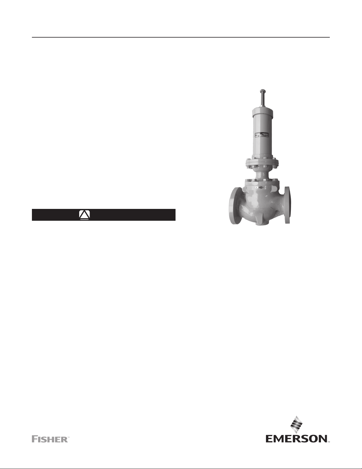
Figure 1. Type CT88
Use qualied personnel when installing,
operating and maintaining the Type CT88
backpressure regulator.
Introduction
Scope of the Manual
This Instruction Manual provides instructions
for the installation, adjustment, maintenance
and parts ordering information of Type CT88
backpressure regulator.
Product Description
The Type CT88 backpressure regulator (Figure 1) is
used to maintain backpressure on Lease Automatic
Custody Transfer (LACT) skids. It is designed to allow
accurate measurement by the positive displacement
pump or coriolis meter and protect other upstream
LACT skid equipment. The high ow capability,
as compared with other backpressure regulators,
maximizes transfer efciency.
Page 2

Type CT88
Specications
The Specications section lists the specications for the Type CT88 backpressure regulators. Factory specication is
stamped on the nameplate fastened on the backpressure regulator at the factory.
Body Sizes
NPS 2, 3 and 4 / DN 50, 80 and 100
End Connection
CL150 RF
Maximum Working Pressure
(1)(4)
Based on CL150 RF Flange Pressure Rating,
See Table 1
Backpressure Control Ranges
(1)(2)
NPS 2 / DN 50: 10 to 145 psi / 0.7 to 10 bar
NPS 3 and 4 / DN 80 and 100: 15 to 145 psi /
1.0 to 10 bar
Wide-Open Flow Coefcients C
v
NPS 2 / DN 50–Cv: 59
NPS 3 / DN 80–Cv: 148
Shutoff Classication
ANSI Class VI
Temperature Capabilities
Fluorocarbon (FKM)
Construction Materials
Body: Carbon steel (WCB)
Diaphragm and Seals: Fluorocarbon (FKM)
Trim Parts: 316 Stainless steel
Control Line Connection Size
1/4 NPT
Approximate Weights
NPS 2 / DN 50: 89 lbs / 40 kg
NPS 3 / DN 80: 131 lbs / 60 kg
NPS 4 / DN 100: 184 lbs / 84 kg
NPS 4 / DN 100–Cv: 240
Flow Characteristic
Quick Open
1. The pressure/temperature limits in this Instruction Manual and any applicable standard limitation should not be exceeded.
2. For lower set pressures, contact the factory.
3. It may be assumed that the material temperature is the same as the working uid temperature.
4. Maximum inlet pressure depends on working temperature (Refer to ASME B16.42 or Table 1).
5. Fluorocarbon (FKM) is limited to 200°F / 93°C for hot water.
6. Increased working temperature may reduce the maximum inlet pressure range (Refer to ASME B16.42 or Table 1).
(1)(3)
(5)
: 20 to 248°F / -7 to 120°C
(6)
Table 1. Pressure-Temperature Ratings for CL150 Carbon steel (WCB)
TEMPERATURE
20 to 100 290
-7 to 38
1. For intermediate temperatures, linear interpolation is permitted.
(1)
°F psi
200 260
248 245
°C bar
50
100
120
Principle of Operation
See Figure 2. Type CT88 direct-operated
backpressure regulator responds to changes in inlet
pressure. Inlet pressure is registered on the underside
of the diaphragm through an external sensing line that
is connected to the lower diaphragm casing.
As long as the inlet pressure remains below setpoint,
control spring keeps the disk against the seat ring
providing tight shutoff with no ow through the
backpressure regulator.
MAXIMUM WORKING PRESSURE
20.0
17.0
17.9
16.9
When inlet pressure rises above the set pressure,
pressure on the diaphragm overcomes the control
spring force. This causes the diaphragm to move
upward, lifting valve stem together with the valve plug
away from seat ring. The ow path through the valve
opens and excess pressure is vented. When upstream
pressure drops below setpoint, the valve closes.
2
Page 3
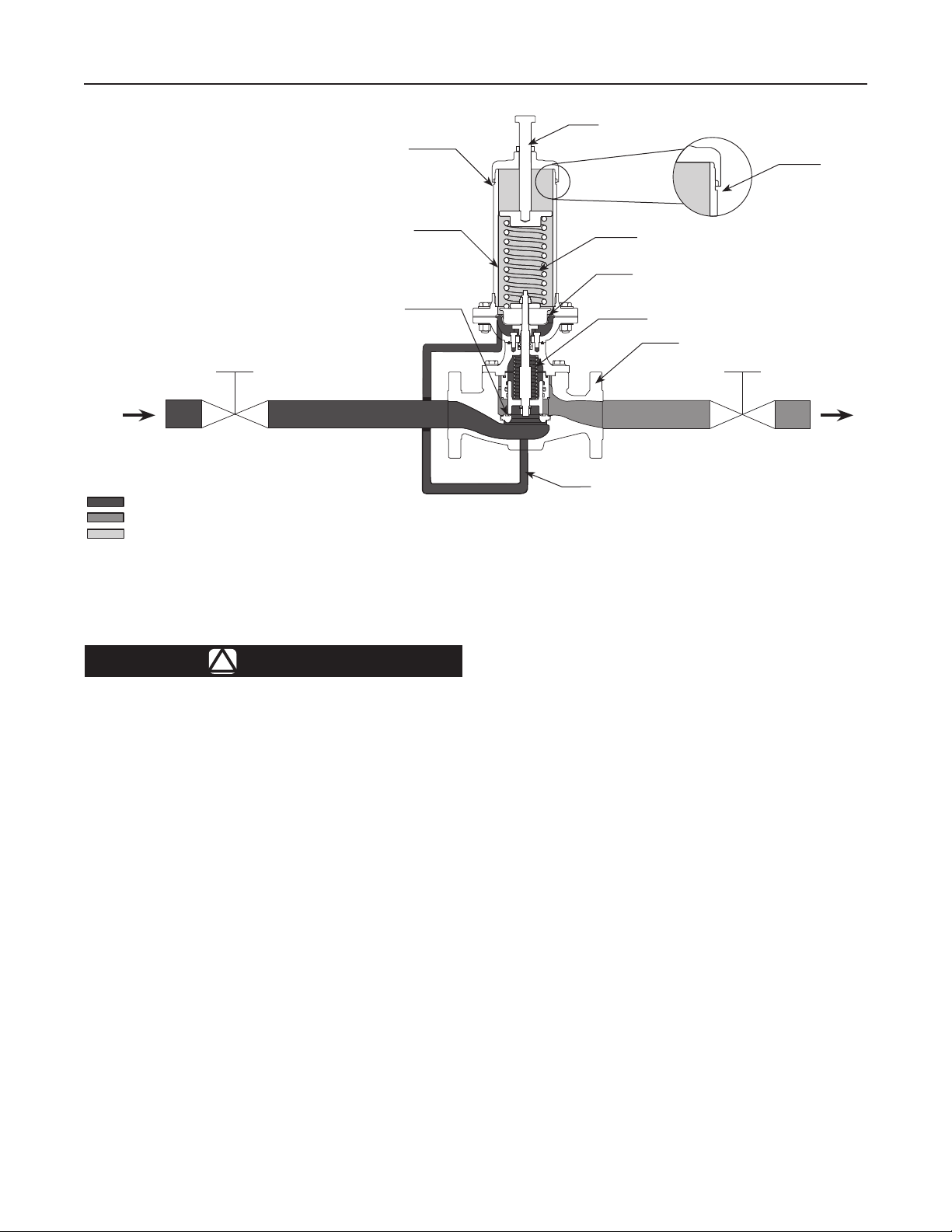
VENT
Type CT88
ADJUSTING SCREW
VENT
INLET PRESSURE
OUTLET PRESSURE
ATMOSPHERIC PRESSURE
Figure 2. Type CT88 Backpressure Regulator Operational Schematic
Installation
WARNING
!
Personal injury or system damage may
result if this backpressure regulator
is installed, without appropriate
overpressure protection, where service
conditions could exceed the limits given
in the Specications section and/or
backpressure regulator nameplate. Refer
to Overpressure Protection section for
recommendations on how to prevent
service conditions from exceeding
those limits.
Additionally, physical damage to the
backpressure regulator may result in
personal injury or property damage due
to escaping of accumulated uid. To
avoid such injury and damage, install the
backpressure regulator in a safe location.
All vents should be kept open to permit
free ow of gas to the atmosphere.
Protect openings against entrance of
rain, snow, insects or any other foreign
material that may plug the vent.
SPRING CASE
SEAT RING
CONTROL SPRING
DIAPHRAGM
VALVE SPRING
BODY
SENSING LINE
Do not install the Type CT88
backpressure regulator in hazardous
or ammable service indoors or in
an enclosure where accumulation of
vented uid may occur. In hazardous
or ammable uid applications, vented
uid may accumulate and cause
personal injury, death, or property
damage due to re, explosion and/or
chemical contamination.
Note
To avoid premature wear of internal
parts, it is recommended that the
actuator be oriented vertically as shown
in Figures 1 and 2.
General Installation Instructions
• Vertical installation with the actuator installed
directly above the main valve is recommended for
optimal performance, as shown in Figures 1 and 2.
• The use of the bleed plug is recommended for
installations of the actuator mounted above the
main valve.
3
Page 4

Type CT88
• The unit will operate in horizontal installations with
the actuator on the side, however, this could result
in premature wear of the parts.
• Make sure that ow will be in the same direction as
indicated by the ow arrow on the body.
Note
For proper backpressure regulator
control and operation, make sure that the
ow arrow matches the ow direction.
CAUTION
To protect against precipitation,
make sure that the actuator is
oriented upward.
Some installations, such as areas with heavy
snowfall, may require a hood or enclosure to protect
the backpressure regulator from snow load and vent
freeze over.
1. Before installing the backpressure regulator:
• Check for damage which might have occurred
during shipment.
• Check and remove any dirt or foreign
material which may have accumulated in the
backpressure regulator body.
• Blow out any debris, dirt or copper sulfate in the
tubing and pipeline.
2. Body installed horizontally with the actuator spring
case pointing upward is recommended.
3. Use gaskets between pipeline and regulator
anges when installing a regulator with anged
end connections. Use approved piping procedures
when installing the regulator.
Overpressure Protection
WARNING
!
Personal injury, equipment damage or
leakage due to escaping accumulated
liquid or bursting of pressure-containing
parts may result if this backpressure
regulator is:
- Overpressurized;
- Used with incompatible process uid;
- Installed where service conditions
could exceed the limits given in the
Specications section and on the
appropriate nameplate; or
- Where conditions exceed any
ratings of adjacent piping or
piping connections.
To avoid such injury or damage, provide
pressure-relieving or pressure-limiting
devices to prevent service conditions
from exceeding those limits.
Overpressuring any portion of this equipment may
result in equipment damage, leaks in the backpressure
regulator or personal injury due to bursting of
pressure-containing parts. The system should be
inspected after any overpressure condition.
The backpressure control range and maximum inlet
pressure can be found in the Specications section.
Startup
WARNING
!
To avoid possible personal injury,
equipment damage or leakage due
to escaping uid, make certain the
backpressure regulator is installed as
instructed in the Installation section.
Escaping process uid from an open
bleed plug may result in backpressure
regulator damage, personal injury and
property damage. To avoid such injury
and damage, make certain the bleed
plug is properly closed after venting air.
Always open bleed plugs slowly. These
plugs contain no packing, so some uid
weepage will occur when the plugs
are opened. Operating personnel must
protect themselves from exposure to
system uids.
CAUTION
Pressure gauges must always be
used to monitor upstream pressure
during startup.
4
Page 5

1. Open the system shutoff valve.
2. Slowly open the outlet block valve.
3. Open the inlet block valve slightly and keep in this
position until pressure is maintained at the desired
setpoint and stabilized.
4. Slowly unscrew the bleed plug to exhaust air that
might have been trapped in the actuator. Screw
and tighten the plug. Exercise caution at all times.
5. If resetting setpoint, then set the regulator
to the desired set pressure according to the
Adjustment procedure.
Adjustment
WARNING
!
Personal injury, equipment damage or
leakage due to escaping uid may result
if adjusting screw and jam nut are not
installed properly.
Always use a pressure gauge to monitor pressure
when making adjustments.
The backpressure regulator spring can be backed
off to 0 psig / 0 bar. Recommended maximum inlet
pressures and temperatures are shown in Table 1.
1. Loosen the jam nut.
2. To increase the setting, turn the adjusting
screw clockwise. Turn the adjusting screw
counterclockwise to decrease the setting.
3. Tighten the jam nut to maintain the desired setting.
Shutdown
WARNING
!
Escaping process uid from an open
bleed plug may result in backpressure
regulator damage, personal injury and
property damage. To avoid such injury
and property damage, make certain
the bleed plug is properly closed after
bleeding process uid.
Type CT88
BLEED PLUG
Figure 3. Diaphragm Case
1. Close the inlet block valve (see Figure 2).
2. Close the outlet block valve.
3. Turn the adjusting screw counterclockwise until all
spring force from the backpressure regulator has
been removed.
4. Slowly open the outlet block valve to release
upstream pressure.
5. Slowly open bleed plug and make sure all pressure
has been relieved from the control line.
Maintenance
WARNING
!
Personal injury, equipment damage
or leakage due to escaping uid may
result if seals are not properly lubricated
or maintained. Due to normal part
wear or damage that may occur from
external sources, this backpressure
regulator should be inspected and
maintained periodically. The frequency
of inspection, maintenance and
replacement of parts depends upon
the severity of service conditions or
the requirements of local, state and
federal regulations.
Backpressure regulators that have been
disassembled for repair must be tested
for proper operation before being returned
to service. Only parts manufactured by
Emerson should be used for repairing
Fisher™ backpressure regulators. Restart
liquid utilization equipment according to
normal startup procedures.
5
Page 6

Type CT88
Note
To protect against reduced performance,
ensure vents are not plugged when
conducting routine maintenance.
• Before maintenance, close the inlet and outlet block
valves and exhaust the pressure in the valve body
and piping as described in the Shutdown section.
• When removing or replacing parts such as the
orice or diaphragm, be careful not to damage it.
• Ensure movable parts can move freely
after reassembly.
• Recommission according to the Installation and
Startup procedures.
• Ensure all connections are tight and check for leaks.
Regular Maintenance
1. Make sure that there is no leakage on the
backpressure regulator and tubing connections.
2. Observe the gauges to make sure that the
pressure being controlled is stable and at the
correct set point.
3. Ensure the pipeline system is clean and free of
foreign materials.
Periodic Maintenance
1. Check Type CT88 backpressure regulator reseat
pressure. Slowly increase the inlet pressure until
the outlet pressure starts to rise, then slowly
decrease the inlet pressure until the outlet
pressure stabilizes. Ensure that the downstream
pressure does not increase.
2. Clean wear parts like the Disk, Diaphragm and
Seat Ring. Make sure to check and replace
deformed and worn out seals when necessary.
3. Check wear parts for damage and replace when
necessary, replace O-rings after disassembly.
Maintenance Instructions for Actuator
Replacement Parts (keys 15, 21, 22, 23,
56 and 68)
Refer to Figure 4 for the Type CT88 Actuator
Assembly, Figure 5 for the NPS 2 / DN 50 body
assembly drawing and Figure 6 for the NPS 3 and 4 /
DN 80 and 100 body assembly drawing.
Actuator Disassembly
1. Isolate the Backpressure Regulator, relieve all
pressure in body and actuator and relieve spring
force by following the procedure described in the
Shutdown section.
2. Loosen and remove sense line from diaphragm
lower casing (key 54).
3. Loosen and remove 8 bolts (key 58), 8 nuts
(key 57) and 8 washers (key 8) around the
actuator ange.
4. Lift the upper casing (key 59) directly upward over
the main spring (key 48). Set aside spring and
upper spring seat (key 50).
5. Loosen and remove 2 hex nuts (keys 60 and 34)
from stem (key 14)
6. Remove lower spring seat (key 37), diaphragm
plate (key 55) diaphragm (key 56), diaphragm
head (key 36) and O-ring (key 68) upward and
over stem (key 14)
pin (key 66) from diaphragm head (key 36).
7. Loosen and remove 4 screws (key 16) and
4 spring washers (key 17).
8. Carefully remove diaphragm lower casing (key 54)
upward and over stem (key 14).
9. Remove bushing (key 20), 2 stem guides (key 21),
O-rings (keys 22 and 23) upward over the stem
(key 14).
10. Remove O-ring (key 15).
(1)
.
(1)
. Do not damage or remove
Actuator Assembly
1. Lightly lubricate O-ring (key 15) and place it into
the body.
2. Carefully place the diaphragm lower casing on
the body, make sure the thread holes on both
of casing and body are aligned. The position of
sense line pipe hole should be aligned with the
sense line pipe hole of the body.
3. Place spring washers (key 17) on screw (key 16),
apply lubricant to the thread of bolts.
4. Bolt body and casing together and tighten screws
(key 16) securely using a multi-pass, criss-cross
pattern. Torque values listed in Table 4.
5. Lightly lubricate O-ring (key 68) and mount it into
the groove of diaphragm head (key 36); Insert the
stem (key 14) through center of the diaphragm
head, and press until it makes contact with
1. Refer to Figures 5 and 6.
6
Page 7

Type CT88
diaphragm lower casing (key 54), make sure the
ribs of the diaphragm head are aligned in between
the screws (key 16) and washers (key 17).
6. Lay the diaphragm (key 56) on the surface
of diaphragm head (key 36); make sure all
diaphragm holes are aligned with the pin (key 66)
and the bolt holes of diaphragm lower casing
(key 54) for the remainder of the assembly steps.
Note
Exercise care to ensure that the
diaphragm (key 56) is not pinched, twisted
or wrinkled while compressing between
the upper and lower diaphragm casings
(keys 59 and 54), diaphragm head and
diaphragm plate (keys 5 and 36).
7. Place the diaphragm plate (key 55) and lower
spring seat (key 37) on the diaphragm in turn and
tighten using two nuts (keys 34 and 60). Thin nut
(key 34) is below the nut (key 60). Make sure the
pin (key 66) is inserted into the hole of diaphragm
plate (key 55). Tighten securely, torque values
listed in Table 4.
Note
Hold the wrench at on top of stem
(key 14) while tightening the nuts
(keys 34 and 60). Make sure the
diaphragm does not move or become
pinched, twisted or wrinkled.
8. Insert upper spring seat (key 50) into the spring
(key 48) and apply lubricant into the hole of the
spring seat that contacts the adjusting screw
(key 53) and to both ends of the spring.
9. Place the spring (key 48) and upper spring seat
(key 50) onto the lower spring seat (key 37).
Note
Make sure the position of stem and
lower spring seat are at the center of
the spring.
10. Place the upper diaphragm casing (key 59) (along
with other attached components) over the spring
(key 48) and upper spring seat (key 50). Align
the bolt holes of the upper diaphragm casing and
lower diaphragm casing.
11. Apply lubricant to the thread of 8 bolts (key 58)
and insert the bolts down through the upper
diaphragm casing (key 59) then through the lower
diaphragm casing (key 54).
12. Place 8 washers (key 8) and 8 nuts (key 57)
onto the 8 bolts (key 58) from below the lower
diaphragm casing (key 54). Tighten the nuts
and bolts using a multi-pass, criss-cross pattern.
Torque values listed in Table 4.
Maintenance Instructions for Body
Replacement Parts (keys 2, 3, 7, 9, 10
and 11)
Refer to Figure 5 for maintenance instructions
for NPS 2 / DN 50 body. Refer to Figure 6 for
maintenance instructions for a NPS 3 and 4 / DN 80
and 100 body.
Body Disassembly
1. Isolate the Backpressure Regulator, relieve all
pressure in body and actuator and relieve spring
force by following the procedure described in the
Shutdown section.
2. Loosen and remove 8 bolts (key 13) and 8
washers (key 8 for NPS 2 / DN 50 and key 26 for
the NPS 3 and 4 / DN 80 and 100 body).
3. Carefully, remove the bonnet (key 12) (along with
all other attached components) upward and out of
the body (key 1).
Note
Some components may stick together
and seem to be connected. Be careful
not to allow these components to drop
or separate unexpectedly e.g. sleeve
(key 6), O-rings (keys 7, 10 and 11) and
sliding ring (key 9).
4. Slide apart sliding ring (key 6) from piston (key 4)
to access 2 sliding rings (key 9) and O-rings
(keys 7 and 10).
5. Remove cage (key 18), seat ring (key 3) and
O-ring (key 2).
6. Replace worn or damaged parts during assembly
by following the procedure described in the Body
Assembly section.
Body Assembly
1. Clean the surface and interior of the body (key 1)
by using penetrating oil, water removal spray,
and/or air gun. Lightly lubricate O-ring (key 2)
and place it on the corner of body/seat ring
(key 3) intersection.
7
Page 8

Type CT88
Table 2. Troubleshooting
PROBLEM POSSIBLE CAUSE POSSIBLE SOLUTION
Backpressure regulator is undersized or oversized Review sizing
Backpressure regulator is not working
Application flow rate exceeds product's advertised capacity Review sizing
Backpressure regulator inlet pressure increases
Debris caught in between disk and seat ring Remove debris
Damaged, deformed or worn out diaphragm Replace diaphragm
Backpressure regulator lock-up
pressure decreases
Debris caught in between disk and seat ring Clean or replace disk
Backpressure regulator inlet pressure fluctuates Actual flow rate much lower than normal
Damaged diaphragm Replace diaphragm
Restrictor or control line is blocked Check restrictor and control line, clean debris
O-ring in disk assembly damaged Replace O-ring
Deformed or worn out disk or seat ring Replace disk or seat ring
Damaged disk assembly O-ring Replace O-ring
Review sizing or check upstream equipment when
upstream pressure fluctuates
Table 3. Spare Parts Kits
BODY SIZE
NPS DN
2 50 RCT88X00F22
3 80 RCT88X00F32
4 100 RCT88X00F42
1. Includes diaphragm, O-rings, stem guide, ring sliding, seat, etc.
2. Place the seat ring (key 3) onto the step inside the
body carefully, make sure the O-ring (key 2) does
not move.
3. Place the cage (key 18) into the groove of the
seat ring (key 3).
4. Lightly lubricate O-ring (key 7) and 2 sliding rings
(key 9), and install the O-ring and sliding rings into
the grooves of the sleeve (key 6) in turn.
5. Lightly lubricate O-ring (key 10) and place it into
the groove at the top of the sleeve (key 6).
6. Insert the trim assembly (key 4 and other attached
components) through the sleeve/sliding ring/
O-ring assembly (keys 6, 7 and 9) from top of the
sleeve, make sure the O-ring (key 7) is not moved
or damaged.
7. Lightly lubricate O-ring (key 11) and place into
the corner of the body/bonnet interface (keys 1
and 12).
8. Insert trim assembly (key 4 and other attached
components) and sleeve/sliding/O-ring assembly
(keys 6, 7 and 9) into body (key 1), press until
piston (key 4) contacts seat ring (key 3) and
sleeve (key 6) contacts cage (key 18).
(1)
SPARE PART NUMBER
9. Carefully align the bonnet (key 12) on to body
(key 1) into the correct orientation.
Note
The sense line hole in the lower diaphragm
casing (key 54) should align with the sense
line hole in the body (key 1).
10. Press bonnet (key 12) down until it contacts the
body (key 1).
11. Apply the lubricant to thread of bolts (key 13), then
bolt together the bonnet and body using washers
(key 8 for NPS 2 / DN 50 and key 26 for the NPS 3
and 4 / DN 80 and 100 body). Tighten bolts using
a multi-pass, criss-cross pattern by using a torque
wrench. Torque values are listed in Table 4.
Parts Ordering
When corresponding with your local Sales Ofce
about this regulator, include the type number and all
other pertinent information stamped on the nameplate.
Specify the part name when ordering new parts
from the following parts list. Separate repair part kits
containing all recommended elastomer spare parts
are available.
8
Page 9

PART NAME
Screw (key 16), 4 required 18.5 to 22.1 25 to 30
Bolts (key 42); Nuts (key 40) 20.7 to 23.6 28 to 32
NPS 2 / DN 50 44.3 to 55.3 60 to 75
Bolts (key 13), 8 required
Hex Nut (key 34) 11.8 to 14 16 to 19
Hex Nut (key 60) 15.5 to 17.7 21 to 24
Bolts (key 45) 18.5 to 22.1 25 to 30
Bolts (key 58), 8 required; Nuts (key 57) 45 to 54.5 61 to 74
Locknut (key 29) 15.5 to 17.7 21 to 24
NPS 3 / DN 80 39.9 to 54.5 54 to 74
NPS 4 / DN 100 69.4 to 94.4 94 to 128
Parts List
Key Description
Type CT88 Spare Part Kits
(Repair Parts kit includes Diaphragm,
O-rings, Stem Guide, Ring Sliding, Seat, etc.) See Table 3
1 Body, Ductile Iron
2 O-ring, Fluorocarbon (FKM)
3 Seat Ring, Stainless steel/Fluorocarbon (FKM)
4 Piston, Stainless steel
5 Valve Spring, Stainless steel
6 Sleeve, Stainless steel
7 O-ring, Fluorocarbon (FKM)
8 Plate Washer, Steel
NPS 2 / DN 50 (16 required) and NPS 3 and 4 /
DN 80 and 100 (8 required)
9 Ring Sliding, 2 required, PTFE/ Molybdenum disulde
10 O-ring, Fluorocarbon (FKM)
11 O-ring, Fluorocarbon (FKM)
12 Bonnet, Carbon steel
13 Bolt, 8 required, Steel
14 Stem, Stainless steel
15 O-ring, Fluorocarbon (FKM)
16 Screw, 4 required, Stainless steel
17 Spring Washer, 4 required, Stainless steel
18 Cage, Stainless steel
19 Plate, Stainless steel
NPS 3 / DN 80
NPS 4 / DN 100
20 Bushing, Stainless steel
21 Stem Guide, 2 required, PTFE
22 O-ring, Fluorocarbon (FKM)
23 O-ring, Fluorocarbon (FKM)
Type CT88
Table 4. Torque Specications
TORQUE FOR ALL BODY SIZES
Ft-Lb N•m
Key Description
24 Plate Washer, 2 required, Steel
26 Plate Washer, 8 required, Steel
NPS 3 / DN 80
NPS 4 / DN 100
29 Locknut, Stainless steel
30 Nameplate
31 Rivet, 6 required
34 Hex Nut, Steel
36 Diaphragm Head, Stainless steel
37 Lower Spring Seat, Lower, Stainless steel
44 Spring Case, Stainless steel
48 Spring, Yellow, Chromium Silicon, 30 to 145 psi / 2 to 10 bar
50 Upper Spring Seat, Carbon steel
51 Spring Cap, Carbon steel
52 Nut, Steel
53 Screw Adjusting, Steel
54 Lower Diaphragm Casing, Lower, Carbon steel
55 Diaphragm Plate, Stainless steel
56 Diaphragm, Fluorocarbon (FKM)
57 Nut, 8 required, Steel
58 Bolt, 8 required, Steel
59 Upper Diaphragm Casing, WCB or Carbon steel
60 Hex Nut, Steel
61 Flow Arrow
65 Drain Valve Manual, Brass
66 Pin, Steel
68 O-ring, Fluorocarbon (FKM)
69 Connector, Steel
67 Restrictor, Stainless steel
9
Page 10

Type CT88
53
52
51
50
30
66
48
44
60
34
37
58
59
8
57
36
68
56
55
17
16
D
54
DETAIL D
65
BLEED PLUG DETAIL
Figure 4. Type CT88 Actuator Assembly
10
Page 11

DETAIL H
Type CT88
31
30
16
17
15
14
61
24
29
13
8
12
11
10
9
4
7
6
21
23
20
3
H
5
18
K
2
1
22
DETAIL K
Figure 5. Type CT88 Body Assembly for NPS 2 / DN 50
11
Page 12

Type CT88
31
DETAIL E
30
16
24
29
15
14
23
22
20
21
17
13
61
12
C
11
10
E
26
DETAIL C
9
7
18
6
5
4 19 3 2
1
Figure 6. Type CT88 Body Assembly for NPS 3 and 4 / DN 80 and 100
Webadmin.Regulators@emerson.com
Fisher.com
Emerson Automation Solutions
Americas
McKinney, Texas 75070 USA
T +1 800 558 5853
+1 972 548 3574
Europe
Bologna 40013, Italy
T +39 051 419 0611
Facebook.com/EmersonAutomationSolutions
LinkedIn.com/company/emerson-automation-solutions
Twitter.com/emr_automation
Asia Pacic
Singapore 128461, Singapore
T +65 6777 8211
Middle East and Africa
Dubai, United Arab Emirates
T +971 4 811 8100
D104030X012 © 2014, 2019 Emerson Process Management Regulator
Technologies, Inc. All rights reserved. 05/19.
The Emerson logo is a trademark and service mark of Emerson
Electric Co. All other marks are the property of their prospective owners.
Fisher™ is a mark owned by Fisher Controls International LLC, a
business of Emerson Automation Solutions.
The contents of this publication are presented for information purposes
only, and while effort has been made to ensure their accuracy, they are
not to be construed as warranties or guarantees, express or implied,
regarding the products or services described herein or their use or
applicability. All sales are governed by our terms and conditions, which
are available on request. We reserve the right to modify or improve the
designs or specications of our products at any time without notice.
Emerson Process Management Regulator Technologies, Inc. does not
assume responsibility for the selection, use or maintenance of any
product. Responsibility for proper selection, use and maintenance of any
Emerson Process Management Regulator Technologies, Inc. product
remains solely with the purchaser.
 Loading...