

Page 1
Instruction Manual
D103545X012
Control-Disk NPS 14-36
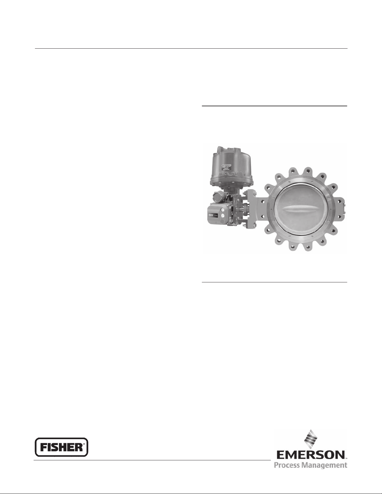
Fisherr Control-Disk™ NPS 14-36 CL150-300
High-Performance Butterfly Valve
April 2011
Contents
Introduction 1.................................
Scope of Manual 1.............................
Description 2.................................
Specifications 2...............................
Installation 3...................................
Valve Orientation 4............................
Before Installing the Valve 4.....................
Adjusting the Actuator Travel 6..................
Installing the Valve 7...........................
Packing Adjustment and Shaft Bonding 9......
Maintenance 11................................
Removing and Replacing the Actuator 11..........
Packing Maintenance 11........................
Removing the Valve 13.........................
Seal Maintenance 13...........................
PTFE Seals 14..............................
NOVEX, Phoenix III and/or
Phoenix III Fire‐Tested Seals 15.............
Anti‐Blowout Design, Packing, Valve Shaft,
Disk, and Bearing Maintenance 16.............
Installing the Two‐Piece Shaft 18.............
Gasket Retainer 20............................
Parts Ordering 20...............................
Parts List 22...................................
Figure 1. Fisher Control-Disk Valve with 1061
Actuator and FIELDVUE™ DVC6020 Digital Valve
Controller
W9138‐1
Introduction
Scope of Manual
This instruction manual includes installation, maintenance, and parts ordering information for NPS 14 through 36,
CL150-300 Control-Disk High‐Performance Butterfly Valves (see figure 1). Refer to separate instruction manuals for
information covering the actuator and accessories.
Do not install, operate, or maintain Control-Disk valves without being fully trained and qualified in valve, actuator, and
accessory installation, operation, and maintenance. To avoid personal injury or property damage, it is important to
carefully read, understand, and follow all the contents of this manual, including all safety cautions and warnings. If you
have any questions about these instructions, contact your Emerson Process Management sales office before
proceeding.
Unless otherwise noted, all NACE references are to NACE MR0175‐2002.
www.Fisher.com
Page 2

Control-Disk NPS 14-36
April 2011
Table 1. Specifications
Instruction Manual
D103545X012
Valve Size and End Connection Styles
J NPS 14, J 16, J 18, J 20, J 24, J 30, or J 36
valves, in J wafer‐style (flangeless) or
J single‐flange (lugged) with raised‐face flanges,
CL150 or CL300
Maximum Pressure Drop
(1)
Consistent with CL150 and CL300
pressure/temperature ratings per ASME B16.34.
Contact your Emerson Process Management sales
office for additional information
Shutoff Classification Per ANSI/FCI 70‐2 and IEC
60534‐4
Standard Soft Seal: Bidirectional shutoff Class VI
(bubble‐tight)
NOVEX Seal: Unidirectional shutoff Class V (reverse
flow direction only)
Phoenix III Seal: Bidirectional shutoff Class VI
(bubble‐tight)
Phoenix III Seal for Fire‐Tested Applications:
Unidirectional shutoff Class VI (reverse flow direction
only) (bubble‐tight). Fire Tested per API 607 Rev. 4.
For cryogenic seal applications, consult your Emerson
Process Management sales office
Flow Coefficient Ratio
(2)
100 to 1
Noise Levels
See Catalog 12 for sound/pressure level prediction
Valve In‐Line Position
Shaft horizontal. See figure 4
Valve/Actuator Action
With diaphragm or piston rotary actuator,
field‐reversible between:
J push‐down‐to‐close (extending actuator rod
closes valve) and
J push‐down‐to‐open (extending actuator rod
opens valve)
Valve Body Classification
NPS 14 to 24: Face‐to‐face dimensions are in
compliance with MSS SP68 and API 609 standards.
Valve bodies are designed for installation between
ASME B16.5 CL150 and CL300 raised‐face flanges
NPS 30 to 36: Valve bodies are designed for
installation between ASME B16.47 CL150 and CL300
raised‐face flanges
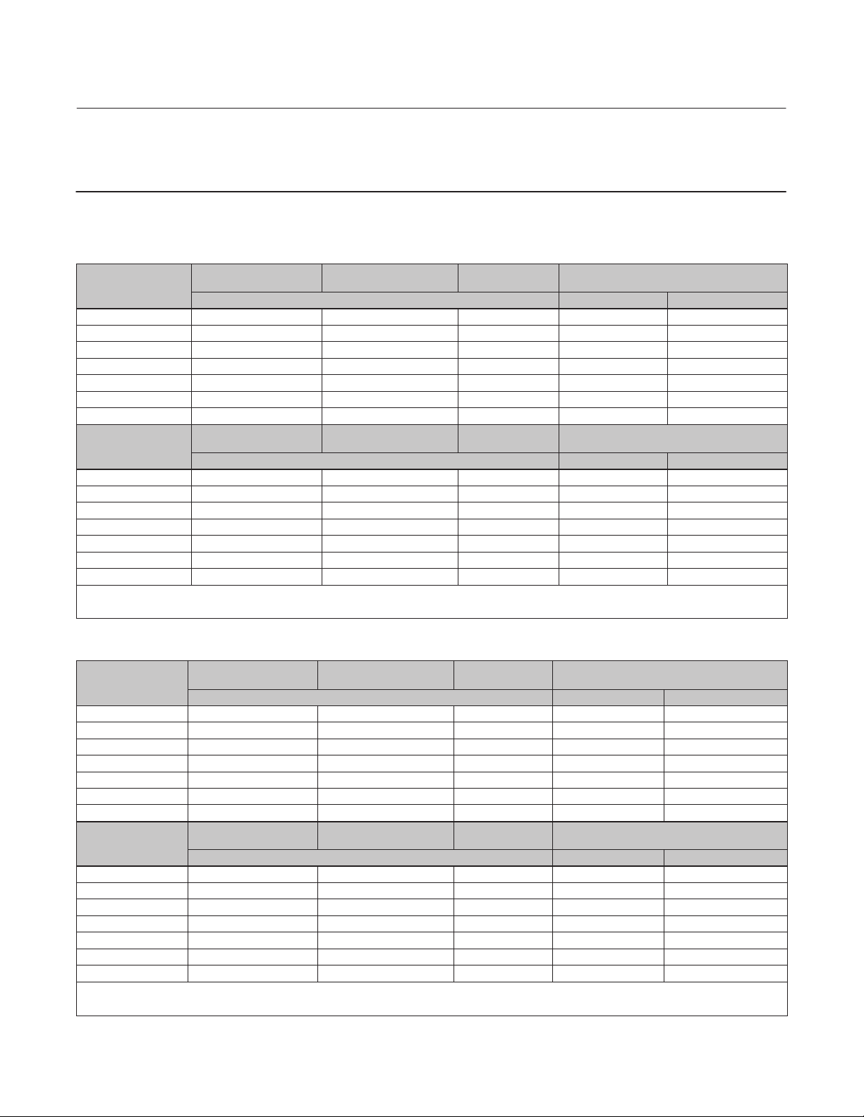
Available Seal Configurations
Standard Constructions
See figure 2 and table 2
Standard Construction Materials
See table 2
Flow Characteristic
Equal percentage
Flow Coefficients
Contact your Emerson Process Management sales
office
1. The pressure/temperature limits in this manual, and any applicable code or standard limitation should not be exceeded.
2. Ratio of maximum flow coefficient to minimum usable flow coefficient may also be called rangeability.
Disk Rotation
Clockwise to close (when viewing from the drive shaft
end) through 90 degrees rotation
Shaft Diameter and Approximate Weight
See tables 3 and 4
ENVIRO‐SEAL™ Packing
This optional packing system provides improved
sealing, guiding, and transmission of loading force to
control liquid and gas emissions. Contact your
Emerson Process Management sales office for
availability of ENVIRO‐SEAL packing
Description
The valve is available in either a flangeless wafer body or a single‐flange (lugged) body design, with a variety of seals
and internal components. The pressure‐assisted seal provides tight shutoff. The upper (splined) shaft combines with a
variety of pneumatic piston or spring‐and‐diaphragm actuators. Maximum inlet pressure/temperature ratings are
consistent with CL150 and CL300.
2
Page 3

Instruction Manual
D103545X012
Table 2. Material Temperature Ratings
COMPONENT AND MATERIAL OF CONSTRUCTION
Body
Carbon Steel (WCC or SA 516-70)
CF8M (316 SST) CL150
CF8M FMS 20B16 (0.04% min carbon) CL300
Disk
CF8M (316 SST) w/ or w/o Hard coating
CF8M with CoCr‐A edge (Alloy 6)
Shaft
S20910
S17400 (17‐4 PH H1025)
S17400 (17‐4 PH H1150M)
Bearings
(2)
PEEK
S31600
Packing
PTFE Packing and PTFE ENVIRO‐SEAL Packing
Graphite packing
Graphite packing with oxidizing media
Graphite ENVIRO-SEAL packing
Seal Ring and
Backup Ring
Seal Ring
(standard)
(3)
PTFE Seal Ring
NBR (Nitrile) Backup O‐Ring
CR (chloroprene) Backup O‐Ring
EPR Backup O‐Ring
Fluorocarbon Backup O‐Ring
PTFE Backup O‐Ring
UHMWPE
NBR Backup O‐Ring
CR Backup O‐Ring
EPR Backup O‐Ring
Fluorocarbon Backup O‐Ring
PTFE Backup O‐Ring
Phoenix III and/or Fire Tested Construction
S31600 and PTFE Seal Ring with NBR Backup O‐Ring
CR Backup O‐Ring
EPR Backup O‐Ring
Fluorocarbon Backup O‐Ring
NOVEX S31600 Seal
NOVEX S31600 Seal
NOVEX S21800 Seal Ring (CL300)
Cryogenic Seal Ring Contact your Emerson Process Management sales office
1. NACE trim constructions are available; consult your Emerson Process Management sales office.
2. PEEK stands for poly‐ether‐ether‐ketone.
3. For a complete material description, contact your Emerson Process Management sales office.
4. UHMWPE stands for ultra high molecular weight polyethylene.
5. Cast or wrought /plate grades used interchangeably, depending upon availability - unless specified by customer.
6. Seal rated for CL150 pressures. For fully rated CL300 seal rating, use NOVEX S21800 seal ring.
(5)
(4)
Seal Ring (CL150 Only)
(3)
Ring (CL150)
(3, 6)
Ring (CL300)
(1)
Control-Disk NPS 14-36
TEMPERATURE RANGE
_C _F
-29 to 427
-198 to 538
-198 to 816
-198 to 538
-198 to 538
-198 to 538
-73 to 427
-196 to 427
-73 to 260
-198 to 816
-54 to 232
-198 to 916
-198 to 538
-7 to 316
-29 to 93
-43 to 149
-54 to 182
-29 to 204
-73 to 204
-29 to 93
-43 to 93
-54 to 93
-29 to 93
-73 to 93
-40 to 149
-54 to 149
-62 to 204
-40 to 232
-29 to 538
-29 to 816
-29 to 816
April 2011
-20 to 800
-325 to 1000
-325 to 1500
-325 to 1000
-325 to 1000
-325 to 1000
-100 to 800
-320 to 800
-100 to 500
-325 to 1500
-65 to 450
-325 to 1500
-325 to 1000
20 to 600
-20 to 200
-45 to 300
-65 to 360
-20 to 400
-100 to 400
-20 to 200
-45 to 200
-65 to 200
-20 to 200
-100 to 200
-40 to 300
-65 to 300
-80 to 400
-40 to 450
-20 to 1000
-20 to 1500
-20 to 1500
Installation
The valve is normally shipped as part of a control valve assembly, with the power actuator mounted on the valve. If the
valve or actuator has been purchased separately, or if the actuator has been removed for maintenance, mount the
actuator on the valve, and adjust actuator travel before installing the valve into the line. This is necessary due to the
measurements that must be made during the actuator calibration adjustment process. Refer to the Actuator
Mounting section of this manual and to the separate actuator instruction manual for mounting and adjusting
instructions before proceeding.
WARNING
To avoid personal injury or property damage resulting from the sudden release of pressure:
3
Page 4

Control-Disk NPS 14-36
April 2011
D Always wear protective gloves, clothing, and eyewear when performing any maintenance operation.
D Do not install the valve assembly where service conditions could exceed the limits given in this manual or on the
nameplates.
D Use pressure‐relieving devices as required by government or accepted industry codes and good engineering practices
to protect from over‐pressurizing the system.
D Check with your process or safety engineer for any other hazards that may be present from exposure to process media.
D If installing into an existing application, also refer to the WARNING at the beginning of the Maintenance section in this
instruction manual.
Instruction Manual
D103545X012
CAUTION
When ordered, the valve configuration and construction materials were selected to meet particular pressure, temperature,
pressure drop, and controlled fluid conditions. Responsibility for the safety of process media and compatibility of valve
materials with process media rests solely with the purchaser and end‐user. Since some body/trim material combinations
are limited in their pressure drop and temperature ranges, do not apply any other conditions to the valve without first
contacting your Emerson Process Management sales office.
1. Isolate the control valve from the line pressure, release pressure from both sides of the valve body, and drain the
process media from both sides of the valve. If using a power actuator, shut off all pressure lines to the power
actuator, release pressure from the actuator, and disconnect the pressure lines from the actuator. Use lock‐out
procedures to be sure that the above measures stay in effect while you are working on the equipment.
See the WARNING at the beginning of the Maintenance section for more information before removing the valve from
the pipeline.
2. Install a three‐valve bypass around the control valve assembly if continuous operation is necessary during
inspection and maintenance of the valve.
3. Inspect the valve to be certain that it is free of foreign material.
4. Be certain that adjacent pipelines are free of any foreign material, such as pipe scale or welding slag, that could
damage the valve sealing surfaces.
CAUTION
Damage to the disk will occur if any pipe flanges or piping connected to the valve interfere with the disk rotation path. If
the piping flange has a smaller inner diameter than specified for schedule 80 piping, measure carefully to be certain the disk
rotates without interference before placing the valve into operation. Minimum inside diameters for flanges or pipe mating
with valves are shown in tables 3 and 4.
Valve Orientation
The valve can be installed in any orientation, however it is recommended that the valve drive shaft be horizontal and
the actuator vertical as shown in figure 4.
Install the valve with the high‐pressure shutoff side in the direction noted by the flow arrow for proper installation, and
see figure 4 for more information.
Before Installing the Valve
WARNING
The edges of a rotating valve disk (key 2, figure 9) close with a shearing, cutting motion. To avoid personal injury, keep
hands, tools, and other objects away from the disk while stroking the valve.
4
Page 5
Instruction Manual
D103545X012
Control-Disk NPS 14-36
April 2011
If the Control-Disk valve is equipped with a fail‐open actuator, cycle the valve into the fully closed position. Ensure the valve
cannot open during installation by using a manual actuator, a constant supply pressure to the pneumatic actuator, or other
steps as necessary.
Table 3. Valve Body Data, CL150
SHAFT DIAMETER AT
VALVE SIZE, NPS
ACTUATOR YOKE
14 31.8 92.1 331.2 79.8 103
16 31.8 102 375.2 106 150
18 39.7 114 418.8 152 191
20 44.5 127 464.1 191 248
24 57.2 154 580.9 286 381
30
36
(3)
(3)
SHAFT DIAMETER AT
VALVE SIZE, NPS
ACTUATOR YOKE
14 1.25 3.63 13.04 176 227
16 1.25 4.00 14.77 233 330
18 1.56 4.50 16.49 336 422
20 1.75 5.00 18.27 421 546
24 2.25 6.06 22.87 630 840
30
36
1. NPS 14 to 24 face‐to‐face dimensions are in compliance with MSS SP68 and API 609 specifications.
2. Minimum I.D. is the minimum pipe or flange I.D. required for disk swing clearance.
3. Contact your Emerson Process Management sales office for information.
(3)
(3)
FACE‐TO‐FACE
DIMENSION
(1)
MINIMUM I.D.
(2)
APPROXIMATE WEIGHT, KILOGRAMS
mm Wafer Single‐Flange
159 723.9 625 824
178 876.3 934 1250
FACE‐TO‐FACE
DIMENSION
(1)
MINIMUM I.D.
(2)
APPROXIMATE WEIGHT, POUNDS
Inches Wafer Single‐Flange
6.25 28.5 1380 1820
7.00 34.5 2060 2750
Table 4. Valve Body Data, CL300
SHAFT DIAMETER AT
VALVE SIZE, NPS
ACTUATOR YOKE
14 44.5 118 304.3 143 249
16 44.5 133 346.2 203 314
18 57.2 149 389.4 253 427
20 76.2 156 442.0 388 568
24 88.9 181 523.2 501 853
30
36
(3)
(3)
SHAFT DIAMETER AT
VALVE SIZE, NPS
ACTUATOR YOKE
14 1.75 4.63 11.98 315 549
16 1.75 5.25 13.63 447 693
18 2.25 5.88 15.32 558 941
20 3.00 6.13 17.40 855 1250
24 3.50 7.13 20.59 1110 1880
30
36
1. Face‐to‐face dimensions are in compliance with MSS SP68 and API 609 specifications.
2. Minimum I.D. is the minimum pipe or flange I.D. required for disk swing clearance.
3. Contact your Emerson Process Management sales office for information.
(3)
(3)
FACE‐TO‐FACE
DIMENSION
mm Wafer Single‐Flange
241 670.6 1070 1520
273 828.0 1470 2150
FACE‐TO‐FACE
DIMENSION
Inches Wafer Single‐Flange
9.50 26.4 2360 3360
10.8 32.6 3240 4730
(1)
(1)
MINIMUM I.D
MINIMUM I.D
.(2)
.(2)
APPROXIMATE WEIGHT,
KILOGRAMS
APPROXIMATE WEIGHT,
POUNDS
5
Page 6
Control-Disk NPS 14-36
April 2011
Instruction Manual
D103545X012
A Control-Disk valve is normally shipped as part of an assembly with an actuator and other accessories such as a valve
positioner. If the valve and actuator have been purchased separately or if the actuator has been removed for
maintenance, properly mount the actuator and adjust valve/actuator travel before inserting the valve into the line.
CAUTION
Damage to the disk will occur if any pipe flanges or piping connected to the valve interfere with the disk rotation path. Be
certain to align the valve accurately to avoid contact between the disk (key 2) and the flanges.
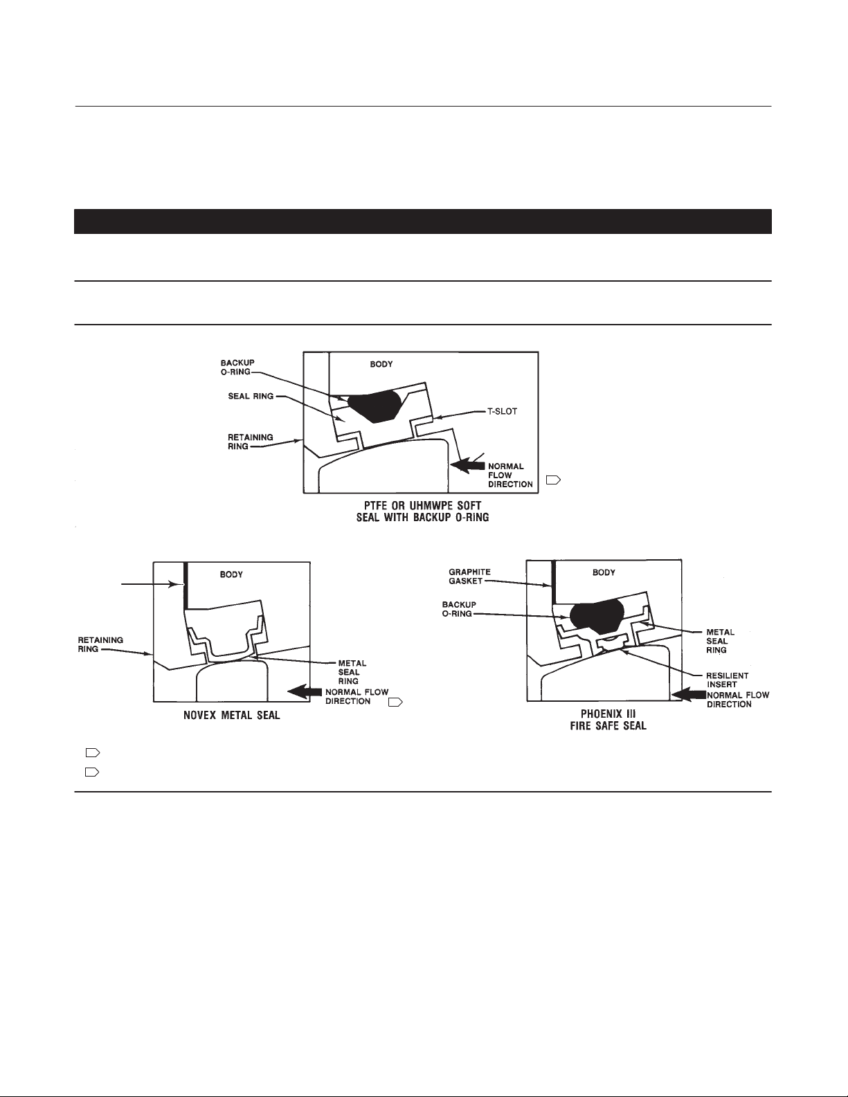
Figure 2. Available Seal Configurations
VALVE DISK
GRAPHITE
GASKET
VALVE DISK
B2313-3
NOTES:
1
THIS UNIDIRECTIONAL SEAL MUST BE INSTALLED SO THAT THE RETAINING RING IS DOWNSTREAM FROM THE HIGH PRESSURE SIDE OF THE VALVE AT
SHUTOFF, AS SHOWN.
2
FOR THIS BIDIRECTIONAL SEAL, THE “PREFERRED” VALVE ORIENTATION PLACES THE RETAINING RING DOWNSTREAM FROM THE HIGH PRESSURE SIDE
OF THE VALVE AT SHUTOFF.
1
2
VALVE DISK
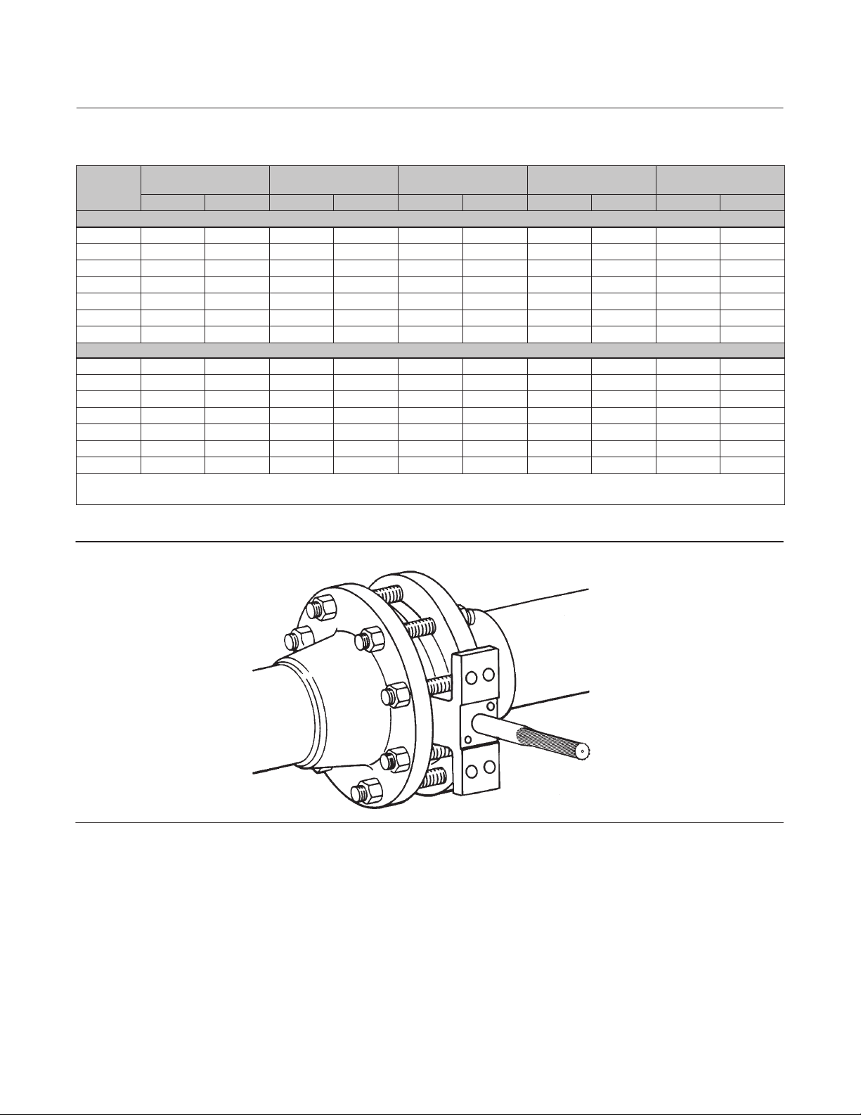
Adjusting the Actuator Travel
Key number locations are shown in figure 9, unless otherwise noted.
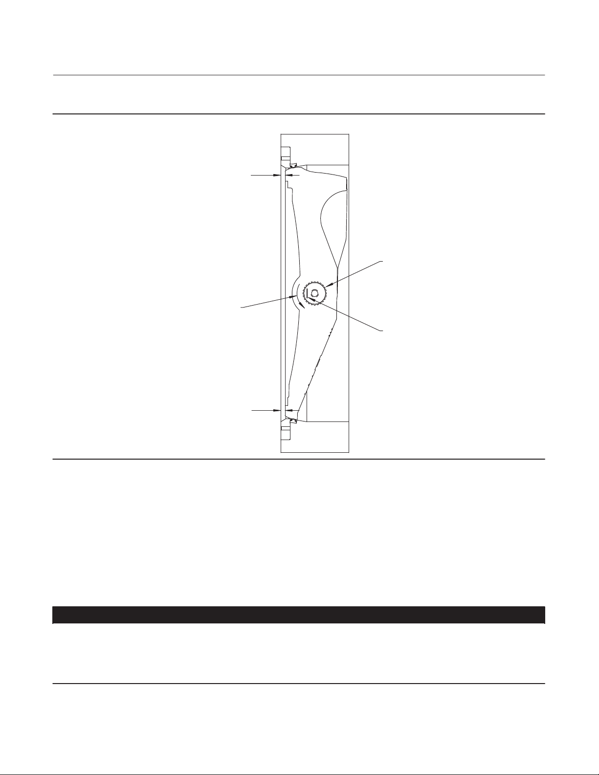
1. Adjust the actuator to bring the disk to the fully closed position at the end of the actuator stroke. To determine the
fully closed disk position, measure the distances between the disk face and the seal retainer face at the top and
bottom of the valve (X1 and X2) as shown in figure 3. Adjust the actuator to rotate the disk slightly until the two
measurements are within 0.8 mm (0.032 inch) of each other. Refer to the appropriate actuator instruction manual
for assistance.
2. Before installing the valve/actuator assembly in the process line, cycle the valve several times to be sure the valve
disk returns to the proper position.
6
Page 7
Instruction Manual
D103545X012
Figure 3. Sectional of Typical Valve Body
CCW DISK
ROTATION
TO OPEN
Control-Disk NPS 14-36
April 2011
X1
ACTUATOR END
OF SHAFT
POSITION INDICATION MARK
INDICATES APPROXIMATE DISK
POSITION
X2
GE53027-A
Installing the Valve
The maximum allowable inlet pressures for Control-Disk valves are consistent with the applicable ASME
pressure/temperature ratings except where limited by the material capabilities as shown in table 2 or figure 2.
Refer to table 5 for the quantity and size of line bolting required to install the valve in the pipeline.
CAUTION
To avoid damage to the valve disk during installation, the valve must be in the fully closed position. If the Control-Disk valve
is equipped with a fail‐open actuator, remove the actuator before installing the valve/actuator assembly or cycle the valve
into the fully closed position. Then, take appropriate steps to be sure that the actuator does not cause the valve to open
during installation.
7
Page 8
Control-Disk NPS 14-36
April 2011
Instruction Manual
D103545X012
Table 5. Hex Head Screw, Stud Bolt and Cap Screw Data
VALVE
SIZE, NPS
14 24 40 ‐ ‐ ‐ ‐ ‐ ‐ 1‐8 1‐1/8‐8 2.75 3.5 ‐ ‐ ‐ ‐ ‐ ‐
16 32 40 ‐ ‐ ‐ ‐ ‐ ‐ 1‐8 1‐1/4‐8 3 3.75 ‐ ‐ ‐ ‐ ‐ ‐
18 32 48 ‐ ‐ ‐ ‐ ‐ ‐ 1‐1/8‐8 1‐1/4‐8 3.25 4 ‐ ‐ ‐ ‐ ‐ ‐
20 40 48 ‐ ‐ ‐ ‐ ‐ ‐ 1‐1/8‐8 1‐1/4‐8 3.5 4 ‐ ‐ ‐ ‐ ‐ ‐
24 40 48 ‐ ‐ ‐ ‐ ‐ ‐ 1‐1/4‐8 1-1/2‐8 3.5 4.5 ‐ ‐ ‐ ‐ ‐ ‐
30 8 8 24 24 1‐1/4‐8 1‐3/4‐8 4.5 5.75 15.5 21.5
36 8 8 28 28 1‐1/2‐8 2‐8 5.25 6.5 18 24.25
14 ‐ ‐ ‐ 8 12 16 1‐8 1‐1/8‐8 ‐ ‐ ‐ 3.5 9.5 12
16 ‐ ‐ ‐ 8 16 16 1‐8 1‐1/8‐8 ‐ ‐ ‐ 3.75 10 13.5
18 ‐ ‐ ‐ 8 16 16 1‐1/8‐8 1‐1/4‐8 ‐ ‐ ‐ 4 11 13.75
20 ‐ ‐ ‐ 8 20 20 1‐1/8‐8 1‐1/4‐8 ‐ ‐ ‐ 4 12 14.5
24 ‐ ‐ ‐ 8 20 20 1‐1/4‐8 1‐1/2‐8 ‐ ‐ ‐ 4.5 14 16.5
30 56 56 ‐ ‐ ‐ ‐ ‐ ‐ 1‐1/4‐8 1‐3/4‐8 4.5 5.75 ‐ ‐ ‐ ‐ ‐ ‐
36 64 64 ‐ ‐ ‐ ‐ ‐ ‐ 1‐1/2‐8 2‐8 5.25 6.5 ‐ ‐ ‐ ‐ ‐ ‐
1. Thread engagement in accordance with ASME B31.3 “Chemical Plant and Petroleum Refinery Piping”.
2. Bolting lengths are based on installation of valve between standard raised face flanges and utilizing flange gaskets with a final compression thickness of 0.125 inch. When gaskets used have
a final compression thickness of less than 0.125 inch, reduce bolting lengths shown by 0.25 inch.
NO. OF CAP SCREWS NO. OF STUD BOLTS
CL150 CL300 CL150 CL300 CL150 CL300 CL150 CL300 CL150 CL300
(1)
SIZE‐DIA. INCH &
THREAD
Single-Flange Style
Wafer-Style
LENGTH OF CAP
SCREWS, INCH
(2)
LENGTH OF STUD BOLTS,
INCH
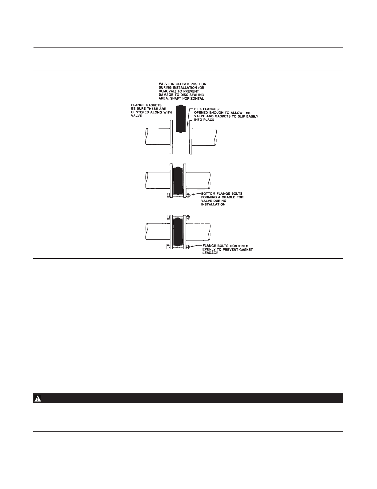
Figure 4. Installation of Wafer‐Style Valves
A5557
1. See figure 4 for recommended valve orientation.
D For Wafer‐Style Valves: Install the lower flange bolts first to form a cradle for the valve (see figure 5). See table 5 for
flange bolt specifications.
D For Single‐Flange Valves: Position the valve between the flanges. Be sure to leave enough room for the flange
gaskets. Install the lower flange bolts.
2. For all Valves: Select the appropriate gaskets for the application. Flat sheet, spiral wound, or other gasket types,
made to the ASME B16.5 standard or user's standard, can be used on Control-Disk valves depending on the service
conditions of the application.
8
Page 9
Instruction Manual
D103545X012
Figure 5. Proper Installation Steps
Control-Disk NPS 14-36
April 2011
B2263‐1
3. For Wafer‐Style Valves: Properly orient the valve according to the specific application. Place the valve in the line so
the flow properly enters the valve as indicated by the flow tag. Then, install the valve and the gaskets between the
flanges into the cradle formed by the flange bolts.
4. Install the remaining flange bolts.
D For Wafer‐Style Valves: Make sure the gaskets are centered on the gasket sealing surfaces of the flange and body.
5. For all Valves: Tighten the flange bolts in an alternating criss‐cross fashion to a torque value of one‐fourth of the
final bolting torque. Repeat this procedure several times, increasing the torque value each time by a fourth of the
final desired torque. After applying the final torque value, tighten each flange bolt again to allow for gasket
compression.
Packing Adjustment and Shaft Bonding
WARNING
Personal injury could result from packing leakage. Valve packing was tightened before shipment; however, the packing
might require some readjustment to meet specific service conditions. Check with your process or safety engineer for any
other hazards that may be present from exposure to process media.
9
Page 10

Control-Disk NPS 14-36
April 2011
Figure 6. Optional Shaft‐to‐Valve Body Bonding Strap Assembly
Instruction Manual
D103545X012
ACTUATOR
A
A
37A6528‐A
A3143‐2
VALVE BODY
VIEW A‐A
CAUTION
For non‐ENVIRO‐SEAL packing: Tighten the packing follower nuts only enough to prevent shaft leakage. Excessive
tightening will accelerate wear of the packing and could produce higher friction loads on the valve stem.
1. For PTFE or graphite packing: Tighten standard packing follower nuts only enough to prevent shaft leakage.
Excessive tightening of packing will accelerate wear and could produce higher rotating friction loads on the valve
stem. If necessary, refer to the Packing Maintenance section.
2. The ENVIRO‐SEAL Packing Systems will not require this initial re‐adjustment. Refer to the separate instruction
manual ENVIRO‐SEAL Packing System for Rotary Valves, D101643X012, for repair and adjustment procedures.
3. For hazardous atmosphere or oxygen service valves, read the following Warning, and provide the bonding strap
assembly mentioned below if the valve is used in an explosive atmosphere.
WARNING
The valve shaft is not necessarily grounded when installed in a pipeline unless the shaft is electrically bonded to the valve.
To avoid personal injury or property damage resulting from the effects of a static electricity discharge from valve
components in a hazardous atmosphere or where the process fluid is combustible, electrically bond the drive shaft (key 3)
to the valve according to the following step.
Note
Standard PTFE packing is composed of a partially conductive carbon‐filled PTFE female adaptor with PTFE V‐ring packing. Standard
graphite packing is composed of all conductive graphite ribbon packing. Alternate shaft‐to‐valve body bonding is available for
hazardous service areas where the standard packing is not sufficient to bond the shaft to the valve (see the following step).
For oxygen service applications, provide alternate shaft‐to‐valve body bonding according to the following step.
4. Attach the bonding strap assembly (key 131, figure 6) to the shaft with the clamp (key 130, figure 6).
10
Page 11

Instruction Manual
D103545X012
5. Connect the other end of the bonding strap assembly to the valve flange cap screws.
6. For more information, refer to the Packing Maintenance section below.
Control-Disk NPS 14-36
April 2011
Maintenance
Valve parts are subject to normal wear and must be inspected and replaced as necessary. The frequency of inspection
and replacement depends upon the severity of service conditions.
Key numbers in this procedure are shown in figure 9 unless otherwise indicated.
WARNING
Avoid personal injury from sudden release of process pressure. Before performing any maintenance operations:
D Always wear protective gloves, clothing, and eyewear when performing any maintenance operations to avoid personal
injury.
D Disconnect any operating lines providing air pressure, electric power, or a control signal to the actuator. Be sure the
actuator cannot suddenly open or close the valve.
D Use bypass valves or completely shut off the process to isolate the valve from process pressure. Relieve process pressure
on both sides of the valve. Drain the process media from both sides of the valve.
D Vent the power actuator loading pressure.
D Use lockout procedures to be sure that the above measures stay in effect while you work on the equipment.
D The valve packing box may contain process fluids that are pressurized, even when the valve has been removed from the
pipeline. Process fluids may spray out under pressure when removing the packing hardware or packing rings, or when
loosening the packing box pipe plug.
D Check with your process or safety engineer for any other hazards that may be present from exposure to process media.
Removing and Replacing the Actuator
Refer to the appropriate actuator instruction manual for actuator removal and replacement procedures.
Packing Maintenance
The Control-Disk valve is designed so the packing can be replaced without removing the valve from the process
pipeline.
CAUTION
For non‐ENVIRO‐SEAL packing: Tighten the packing follower nuts only enough to prevent shaft leakage. Excessive
tightening will accelerate wear of the packing and could produce higher friction loads on the valve stem.
Usually, packing leakage can be eliminated by merely tightening the hex nuts (key 15) located above the packing
follower (key 11) while the valve is in the pipeline. However, if leakage continues, the packing must be replaced.
For PTFE ENVIRO‐SEAL packing systems, refer to the separate instruction manual, ENVIRO‐SEAL Packing System for
Rotary Valves, D101643X012, (see figure 10).
11
Page 12

Control-Disk NPS 14-36
April 2011
Figure 7. Anti‐Blowout Design Details
HEX
NUT
PACKING
FOLLOWER
BELLEVILLE
SPRINGS
PACKING
Instruction Manual
D103545X012
STUD
HEX
JAM
NUT
ANTI
BLOWOUT
FOLLOWER
C0758‐1
CUTAWAY, INTERNAL DETAILS
34B7524‐B
CUTAWAY, ENVIRO-SEAL
PACKING ASSEMBLY
CAUTION
Never use a wrench or pliers on the splined (upper) shaft (key 3). A damaged shaft could cut the packing and allow leakage.
1. Before loosening any parts on the valve, release the pressure from the pipeline. Then, remove the hex nuts (key 15)
and lift off the packing follower (key 11).
2. Remove the hex jam nuts (key 17) and the anti‐blowout flange (key 10). Remove the packing follower (key 12).
Refer to figure 7 for details of the anti‐blowout design parts.
The packing is now accessible.
3. Use a packing extractor to remove packing. Insert the corkscrew‐like end of the tool into the first piece of packing
and pull firmly to remove the packing. Repeat this process until all packing parts have been removed.
12
Page 13

Instruction Manual
D103545X012
Control-Disk NPS 14-36
April 2011
CAUTION
Be careful when cleaning the packing box. Scratches to the upper shaft (key 3) or inside diameter of the packing bore might
cause leakage.
4. Before installing new packing, clean the packing box.
5. Install new packing one ring at a time, using the packing follower as a driver. If using split‐ring packing, stagger the
splits in the rings to avoid creating a leak path.
6. Reinstall packing parts. Refer to figure 9 for sequence of packing parts.
Removing the Valve
1. Disconnect any operating lines providing air pressure, electric power, or a control signal to the actuator. Be sure the
actuator cannot suddenly open the valve. Vent the power actuator loading pressure.
2. Use bypass valves or completely shut off the process to isolate the valve from process pressure. Relieve process
pressure on both sides of the valve. Drain the process media from either side of the valve.
CAUTION
Damage to the valve disk can occur if the disk is not closed when the valve is being removed from the pipeline. If necessary,
stroke the actuator to place the disk in the closed position while removing the valve from the pipeline.
3. Loosen the flange bolting that holds the valve. Make sure the valve cannot slip or twist while loosening and
removing the bolting.
4. Before removing the valve from the pipeline, make sure the valve disk is closed. Removing the valve with the disk
open could cause damage to the disk, piping, or pipe flanges.
5. After removing the valve from the pipeline, move the valve to an appropriate work area. Always support the valve
properly.
6. When valve maintenance is complete, refer to the Installation procedures in this manual.
Seal Maintenance
Note
For larger valves, it is possible to replace the seal (key 5) while the actuator is mounted to the valve and can be accomplished by
cycling the valve to 90 degrees open.
Key numbers in this procedure are shown in figure 9 unless otherwise indicated.
1. After removing the valve from the pipeline, remove the manual or power actuator. Manually rotate the upper shaft
(key 3) counterclockwise until the disk has moved a full 180 degrees away from the closed position.
WARNING
Avoid personal injury or property damage caused by the impact of a falling or tipping of a large valve. Support large valves
during maintenance.
13
Page 14

Control-Disk NPS 14-36
April 2011
Instruction Manual
D103545X012
2. Lay the valve flat on a work bench in a secure position with the retaining ring (key 18) and retaining ring screws (key
19) facing up. Properly secure the valve on a suitable worktable so it cannot slip, twist, or fall during maintenance.
Remove all retaining ring screws.
3. Remove the retaining ring by placing a socket head cap screw from the retaining ring in each of the two retaining
ring jacking screw holes. Slowly turn the screws until the retaining ring has been lifted from the valve body. Remove
the retaining ring to expose the seal in the T‐slot area of the valve body.
Note
The Control-Disk valve is available with different seal designs and components. See figure 2 to identify the specific seal design.
CAUTION
In the following procedure, take care not to damage the seal or T‐slot area of the valve body during removal of the seal.
4. Insert a regular screwdriver or other similar tool under the top edge of the seal and gently pry the seal out of the
T‐slot area in the valve body. Take care not to damage the seal or T‐slot area of the valve body. After the seal has
been removed, clean the T‐slot area, retaining ring and, if required, polish the disk (key 2) thoroughly with fine steel
wool or other appropriate material.
To install a new seal, O‐ring (key 6), and retaining ring gasket, follow the appropriate instructions given below.
Table 6. Torque Values for Fasteners
FASTENER NOMINAL SIZE
#10 4.6 41 4.0 35
1/4 11 100 9.2 81
5/16 25 220 19 167
3/8 45 400 33 295
7/16 72 53 53 39
1/2 112 83 80 59
9/16 161 119 117 86
5/8 225 166 161 119
3/4 401 296 286 210
7/8 651 480 447 330
1 976 720 651 480
1‐1/8 1356 1000 837 617
Note: These values are based upon standard materials, S66286/N07718 screws and ASTM A193GRB6 bolts. For other special fastener materials, please contact your Emerson Process
Management sales office.
RETAINING RING SCREWS GASKET RETAINING BOLTS
NSm InSlbs NSm InSlbs
NSm ftSlbs NSm ftSlbs
PTFE Seals
1. Locate the replacement seal ring (key 5) and note the shape of the ring. The ring is wider across one edge diameter
and narrower across the other edge diameter. Around the outside circumference is one wide groove.
Before installing the seal ring into the valve body, place the O‐ring (key 6) into the wide, outer groove of the seal ring.
Refer to figure 8.
2. Install the seal ring and O‐ring assembly in the valve body. The wider outside diameter of the seal ring goes into the
T‐slot area of the body (see figure 5). Start the edge with the wider diameter into the T‐slot of the valve body using
a blunt‐end screwdriver. If you have a maintenance kit, use the seal installation tools.
14
Page 15

Instruction Manual
D103545X012
Figure 8. Typical Seal Installation
Control-Disk NPS 14-36
April 2011
A5251‐1*
3. Carefully tuck the O‐ring downward into the body T‐slot until the seal ring is completely entrapped in the body
T‐slot, and it completely covers the backup O‐ring.
4. Re‐install the retaining ring and the socket head cap screws. Tighten the cap screws just enough to eliminate any
movement of the retaining ring. Do not over‐tighten the retaining ring screws. Using a blunt‐end tool, carefully
tuck the lip of the seal ring under the retaining ring.
5. When the seal is under the lip of the retaining ring, continue to tighten the cap screws according to standard
procedures. Do not fully torque the screws at this time. Final tightening of the screws is accomplished in step 7 of
this procedure.
6. Manually rotate the upper shaft clockwise 180 degrees to return the disk (key 2) to its closed position.
7. The final seating of the retaining ring cap screws can now be done. For the screw torque values, refer to table 6. The
seal is now fully installed. Refer to the Installation procedures in this manual.
NOVEX, Phoenix III and/or Phoenix III Fire‐Tested Seals
1. Locate the replacement seal ring (key 5) and note the shape of the ring. The ring is wider across one edge diameter
and narrower across the other edge diameter as shown in figure 8. Around the outside circumference is one wide
groove.
Install the seal ring (key 5) in the valve body by first placing the wider outside diameter of the seal ring into the T‐slot
area of the valve body which is shown in figure 2.
The backup O‐ring (key 6) for the Phoenix III seal will have to be installed after placement of the seal ring in the valve
body using a blunt‐end screwdriver or the seal installation tool in the maintenance kit. Do not use the screwdriver or
seal tool directly on the metal seat. Use tools on the O‐ring only.
15
Page 16

Control-Disk NPS 14-36
April 2011
2. With the seal ring inserted all the way around the body T‐slot now lay the O‐ring into the opening between the
valve body and the seal ring. Use the seal tool to apply pressure to the O‐ring and carefully tuck the O‐ring down
into the T‐slot between the valve body and the seal ring.
Note
On larger valves, it may be more efficient to have someone hold down the seal ring while you push the O‐ring into the T‐slot.
3. Once the seal ring and backup O‐ring have been fully installed into the body T‐slot, the retaining ring gasket can be
installed. This gasket is a thin graphite material. Punch one initial screw hole through the gasket for alignment,
being careful not to cause additional damage to the gasket.
4. Install the retaining ring and align the screw holes in the retaining ring with the holes in the valve body. Install the
first retaining ring screw through the punched hole in the ring gasket. Install the other ring screws by pushing the
screws through the graphite gasket and threading them into the valve body.
5. Tighten the retaining ring socket head cap screws just enough to eliminate any movement of the retaining ring. Do
not over‐tighten the retaining ring screws.
Instruction Manual
D103545X012
WARNING
Avoid personal injury or property damage caused by the impact of a falling or tipping of a large valve. Support large valves
during maintenance.
6. To complete this step, stand the valve up. Support the valve securely using methods appropriate for the valve size.
If a vise or other clamps are being used, be sure to not damage the flange gasket sealing area of the valve body.
7. Manually rotate the upper shaft (key 3) to turn the disk clockwise to meet the seal.
8. Adjust the actuator to bring the disk to the fully closed position at the end of the actuator stroke. To determine the
fully closed disk position, measure the distances between the disk face and the seal retainer face at the top and
bottom of the valve (X1 and X2) as shown in figure 3. Adjust the actuator to rotate the disk slightly until the two
measurements are within 0.8 mm (0.032 inch) of each other. Refer to the appropriate actuator instruction manual
for assistance.
9. The final seating of the retaining ring screws can now be done. For the screw torque values, refer to table 6.
Anti‐Blowout Design, Packing, Valve Shaft, Disk, and Bearing
Maintenance
Note
The Control-Disk valve has a two‐piece shaft. In these procedures, the shaft (with the splined end) is called the upper shaft (key 3).
The shaft opposite the upper shaft is called the lower (follower) shaft (key 4).
CAUTION
When removing the actuator from the valve, do not use a hammer or similar tool to drive the lever off the valve shaft.
Driving the lever or actuator off the valve shaft could damage the valve internal parts.
16
Page 17

Instruction Manual
D103545X012
If necessary, use a wheel puller to remove the lever or actuator from the valve shaft. It is okay to tap the wheel puller screw
lightly to loosen the lever or actuator, but hitting the screw with excessive force could also damage internal valve parts.
Control-Disk NPS 14-36
April 2011
Key numbers in this procedure are shown in figure 9 unless otherwise indicated.
1. Remove the valve from the pipeline. Remove the actuator from the valve.
CAUTION
Never use a wrench, pliers, or similar tool to turn the upper shaft. A damaged shaft can cut the packing and allow leakage.
Note
It is not necessary to remove the retaining ring and valve seal when removing the shaft(s) and disk.
WARNING
Avoid personal injury or property damage caused by the impact of a falling or tipping of a large valve. Support large valves
during maintenance.
2. Properly secure the valve on a suitable worktable so it cannot slip, twist, or fall during maintenance.
3. Removing the Anti‐Blowout Design:
a. For PTFE or Graphite Packing: Remove the hex nuts (key 15) and pull off the packing follower (key 11). Remove
the hex jam nuts (key 17) and the anti‐blowout flange (key 10). Remove the anti‐blowout gland (key 12). See
figure 7.
b. For ENVIRO‐SEAL Packing System: Remove the hex nuts (key 101), the packing follower (key 102), jam nuts (key
17), anti‐blowout flange (key 10), and the spring pack assembly (key 103). See figure 10.
4. Remove the packing from around the upper shaft.
5. Remove the tangential pins or disk pins. Locate the pins (key 9) in the upper shaft (key 3) and the pin in the lower
shaft (key 4), if the valve has a two‐piece shaft.
a. If a maintenance kit is available, use the pin extractor to remove the disk pins. Select the correct size pin
extractor tip with screws of proper thread size to match the thread size in the disk pins. If you do not have a kit,
see steps c and d below.
b. Screw the pin extractor tip into the pin as far as possible. With an upward, straight sliding motion, pull out the
pin. Repeat the same procedure for the other pins.
c. You can use a threaded rod with an appropriate spacer (tube) and nut as an extractor tool. If you use a threaded
rod, choose a rod with threads that fit the inside thread of the pins. The rod should extend several inches above
the disk when it is screwed into a pin.
d. After screwing the rod into the pin, slide the spacer over the rod and pin. Thread a nut onto the rod and tighten
it. As you tighten the nut, the nut will drive the spacer against the disk. The increasing force will draw the pin
from the disk.
17
Page 18

Control-Disk NPS 14-36
April 2011
Instruction Manual
D103545X012
6. The gasket retainer (key 20) on the side of the valve opposite the upper shaft must be removed before removing
the lower shaft.
Remove the hex head bolts (key 23) and lockwashers (key 22) from the gasket retainer and remove the gasket retainer
and gasket (key 21) to expose the end of the lower shaft.
7. Before removing the lower shaft (key 4), be sure the valve disk is properly supported. Pull the lower shaft from the
valve body. Use a shaft extractor screwed into the puller hole in the end of the lower shaft.
8. Before removing the upper shaft (key 3), be sure the valve disk is properly supported. Pull out the upper shaft (key
3) by hand‐pulling or by using a shaft extractor screwed into the end of the shaft.
CAUTION
To avoid damage to the disk, seal, and T‐slot area, do not force the disk past the seal or T‐slot area. Remove the disk from
the opposite side of the valve body.
Note
Both the upper shaft and the lower shaft have a thrust bearing (key 24) between the disk and the bearings (key 7). The thrust
bearing is located outside of the bearing bore which holds the bearings. Use care when removing the valve disk to avoid loss of or
damage to the thrust bearings.
9. After removing the shaft(s), remove the disk. Do not force the disk past the seal or T‐slot area. Collect the thrust
bearings.
10. Remove the bearings (key 7). Using a suitable punch or puller, drive or pull the bearings into the valve body bore
from the upper shaft bearing bore. Remove the bearing from the lower shaft bearing bore.
11. Inspect the valve body bore, bearings, bearing bores, and packing box for damage.
Note
In these instructions, the drive shaft (with splined end) is called the upper shaft (key 3). The shaft opposite the upper shaft is called
the lower (follower) shaft (key 4).
Installing the Two‐Piece Shaft
Key numbers in this procedure are shown in figure 9 unless otherwise indicated.
WARNING
Avoid personal injury or property damage caused by the impact of a falling or tipping of a large valve. Support large valves
during maintenance.
1. Properly secure the valve on a suitable worktable so it cannot slip, twist, or fall during maintenance. Be prepared to
support the valve disk.
Note
Replacement disk and shafts are provided as a matched set and both should be replaced at the same time.
18
Page 19

Instruction Manual
D103545X012
Control-Disk NPS 14-36
April 2011
2. Inspect all parts removed from the valve for wear or damage. Replace any worn or damaged parts. Clean the valve
body and all parts to be installed with an appropriate solvent or degreaser.
Note
When installing the bearings, apply lubricant to the outside diameter of the bearing for ease of installation.
CAUTION
Premature valve failure and loss of process control may result if bearings are improperly installed or are damaged during
installation.
3. When installing the lower bearings (key 4), insert one or more bearings into the lower shaft bearing bore so it is
flush with the body bore.
The number of bearings required changes with valve size and construction. Two bearings are required in the upper
shaft and two bearings in the lower shaft. If using an NPS 14 CL150 valve with metal bearings, four bearings in the
upper and four in the lower shaft will be required.
4. Hold the lower shaft thrust bearing (key 24) in the valve body bore against the counterbore of the lower shaft
bearing bore. Push the lower shaft into the bearing bore just enough to hold the thrust bearing.
5. When installing the upper bearing (key 7), insert one or more bearings into the upper shaft from the body bore into
the bearing bore below the packing box. Use caution to prevent damage to the bearing.
6. Hold the upper shaft thrust bearing (key 24) in the valve body bore against the counterbore of the upper shaft
bearing bore. Push the upper shaft through the packing box side into the bearing bore just enough to hold the
thrust bearing.
7. When installing the lower bearing (key 4), insert one or more bearings into the lower shaft bearing bore so it is flush
with the body bore.
8. Insert the lower shaft through the bore in the valve body uncovered by removal of the gasket retainer. Hold the
lower shaft thrust bearing (key 24) in the valve body bore against the counterbore of the lower shaft bearing bore.
Push the lower shaft into the bearing bore just enough to hold the thrust bearing.
CAUTION
To avoid damage to the disk, seal, and T‐slot area, do not force the disk past the seal or T‐slot area. Install the disk from the
opposite side of the valve body.
9. Place the flat side of the disk on a flat surface and insert wooden blocks to raise the disk approximately 51 mm (2
inches) from the worktable surface. Then, suspend the valve body over the disk so the seal/T‐slot area is facing up.
Align the shaft bores through the disk with the upper shaft and lower shaft bores. Lower the valve body over the
disk using caution not to dislodge or damage the thrust bearings placed on the ends of the shafts.
10. With the disk (key 2) properly positioned in the valve body (key 1), push the upper shaft and lower shaft the rest of
the way through the thrust bearings and into the shaft bores in the valve disk.
11. Align the holes in the shafts with the holes in the disk.
19
Page 20

Control-Disk NPS 14-36
April 2011
Instruction Manual
D103545X012
CAUTION
To avoid damage to the tangential pins, disk pins, valve disk, or shaft(s) resulting from the application of excessive force,
use appropriate care when driving the pins into the disk hub and shaft(s). Use the right tool. Do not use excessive force.
12. Install the appropriate tangential pins, and disk pins. Use 2 tangential pins that will go through the upper shaft and
1 disk pin that will go through the lower shaft.
13. Refer to the Anti‐Blowout Design, Packing, Valve Shaft, Disk and Bearing Maintenance procedures in this manual
to re‐install the packing and anti‐blowout design.
Gasket Retainer
Valves with a two‐piece shaft use a gasket retainer and gasket (keys 20 and 21) to cover the lower shaft opening in the
valve body. The gasket is held in place by the gasket retainer and four hex head bolts and lockwashers (keys 23 and
22). When re‐assembling the valve, use a new gasket.
Be sure to center the gasket over the lower shaft bore before retightening bolts. Tighten down bolts evenly in a
crossover or star pattern.
Refer to table 6 for proper torque values.
Parts Ordering
Typical parts are shown in figure 9.
When corresponding with your Emerson Process Management sales office about a Control-Disk valve, identify the
valve as a Control-Disk and provide the valve serial number. For valve/actuator combinations assembled at the factory,
the valve serial number is stamped on the nameplate attached to the actuator.
WARNING
Use only genuine Fisher replacement parts. Components that are not supplied by Emerson Process Management should not,
under any circumstances, be used in any Fisher valve, because they may void your warranty, might adversely affect the
performance of the valve, and could cause personal injury and property damage.
Note
Neither Emerson, Emerson Process Management, nor any of their affiliated entities assumes responsibility for the selection, use, or
maintenance of any product. Responsibility for the selection, use, and maintenance of any product remains with the purchaser and
end user.
20
Page 21

Instruction Manual
Control-Disk NPS 14-36
D103545X012
Retrofit Kits
Retrofit kits include all parts required for installation of the ENVIRO‐SEAL packing system into existing
high‐performance butterfly valves. Retrofit kits are available for single PTFE packing.
See table 7 for retrofit kit part numbers.
Retrofit Kit Included Parts
Key Description Quantity
10
17
100
101
102
103
105
106
107
111
112
1. Not included in graphite packing kit.
2. Only 1 req'd for NPS 18 CL300, NPS 20 CL150 and NPS 24 CL150.
Anti‐blowout follower
Jam nut
Packing stud
Packing nut
Packing flange
Spring pack assembly
Packing Set
Anti‐extrusion washer
Packing box ring
Tag
Cable
2
2
April 2011
1
1
2
2
1
1
1
(1)
(2)
1
1
Note: Key 103, the spring pack assembly, is made up of the packing spring stack held in place by an O‐ring on the
packing follower.
Repair Kits
PTFE Repair kits include a single PTFE packing set and anti‐extrusion washers. Graphite packing sets include graphite
packing rings and carbon anti‐extrusion rings. See table 7 for PTFE repair kit part numbers.
Table 7. Retrofit and Repair Kit Part Numbers
VALVE SIZE, NPS PRESSURE RATING
14
16
18
20 CL150 50.8 (2) RRTYXRT0652 RRTYX000182
24 CL150 63.5 (2‐1/2) RRTYXRT0662 RRTYX000222
30, 36 No kit available
1. Shaft diameter: Diameter through the packing box.
2. For larger shaft sizes, consult your Emerson Process Management sales office.
CL150 34.9 (1‐3/8) RRTYXRT0592 RRTYX000172
CL300 50.8 (2) RRTYXRT0602 RRTYX000182
CL150 38.1 (1‐1/2) RRTYXRT0612 RRTYX000192
CL300 57.2 (2‐1/4) RRTYXRT0622 RRTYX000202
CL150 44.5 (1‐3/4) RRTYXRT0632 RRTYX000212
CL300 63.5 (2‐1/2) RRTYXRT0642 RRTYX000222
SHAFT
DIAMETER
mm (Inch)
(1)(2)
,
RETROFIT KITS REPAIR KITS
PTFE PTFE
21
Page 22

Control-Disk NPS 14-36
April 2011
Parts List
Instruction Manual
D103545X012
Key Description Part Number
Note
Part numbers are shown for recommended spares only. For part
numbers not shown, contact your Emerson Process Management sales
office.
Key Description Part Number
1 Valve Body
If you need a valve body as a replacement part, order the
valve size, Class and desired material. Contact your
Emerson Process Management sales office.
2 Disk
3 Drive Shaft
4 Follower Shaft
5* Seal Ring (See following table)
6* Backup Ring (See following table)
7* Bearing (See following table)
9 Tangential Pin / Disk Pin
10 Anti‐Blowout Flange
11 Packing Flange
12 Packing Follower
13* Packing Set
PTFE, V‐Ring
CL150
NPS 14 V111433X012
NPS 16 V167865X012
NPS 18 V110460X012
NPS 20 V111437X012
NPS 24 V111699X012
NPS 30 V111704X012
NPS 36 V121811X012
CL300
NPS 14 V111437X012
NPS 16 V110631X012
NPS 18 V111699X012
NPS 20 V111704X012
NPS 24 V111708X012
NPS 30 V121593X012
NPS 36 V122149X012
Graphite
CL150
NPS 14 V111434X012
NPS 16 V167864X012
NPS 18 V111028X012
NPS 20 V111438X012
NPS 24 V111442X012
NPS 30 V111705X012
NPS 36 V129596X012
CL300
NPS 14 V111438X012
NPS 16 V111696X012
NPS 18 V111442X012
NPS 20 V111705X012
NPS 24 V111709X012
NPS 30 V115138X012
NPS 36 V115155X012
14 Stud (2 req'd)
15 Hex nut (2 req'd)
17 Hex Jam Nut (2 req'd)
18 Retaining Ring
19 Retaining Ring Screw
20 Gasket Retainer
21* Gasket (See following table)
22 Lockwasher (4 req'd)
23 Cap Screw (4 req'd)
24* Thrust Bearing (See following table)
26* Retaining Ring Gasket
NOVEX and Phoenix III Seal
Standard & NACE
CL150
NPS 14 V161467X012
NPS 16 V161468X012
NPS 18 V161469X012
NPS 20 V112062X012
NPS 24 V161471X012
NPS 30 V168292X012
NPS 36 V124869X012
CL300
NPS 14 V113741X012
NPS 16 V112064X012
NPS 18 V161469X012
NPS 20 V112062X012
NPS 24 V124867X012
NPS 30 V124882X012
NPS 36 V124883X012
Oxygen Service
CL150
NPS 14 V161467X022
NPS 16 V161468X022
NPS 18 V161469X022
NPS 20 V169962X012
NPS 24 V161471X022
NPS 30 V168292X022
NPS 36 V124869X022
CL300
NPS 14 V113741X022
NPS 16 V112064X022
NPS 18 V161469X022
NPS 20 V112062X022
NPS 24 V124687X022
NPS 30 V124882X022
NPS 36 V124883X022
27 Cap Screw - Actuator (4 req'd)
28 Hex Nut - Actuator (4 req'd)
29 Nameplate (not shown)
32 Drive Screw (2 req'd) (not shown)
33 Flow Direction Arrow (not shown)
34 Packing Box Ring
35 Disk/Shaft/Pin Assembly
22
*Recommended spare parts
Page 23

Instruction Manual
D103545X012
Control-Disk NPS 14-36
April 2011
ENVIRO‐SEAL Packing System
(See figure 10)
Key Description Part Number
10 Anti‐Blow Flange
17 Hex Jam Nut (4 req'd)
100 Packing Flange Stud (4 req'd)
101 Packing Flange Nut (4 req'd)
102 Packing Flange, SST
103 Spring Pack Assembly
105* Packing Set
Use with PTFE packing
CL150
NPS 14 14B3490X012
NPS 16 14B3495X012
NPS 18 13B9155X012
NPS 20 13B9164X012
NPS 24 12B7782X012
CL300
NPS 14 13B1964X012
NPS 16 14B3647X012
NPS 18 12B7782X012
NPS 20 13B9164X012
NPS 24 14B5730X012
Use with Graphite packing
CL150
NPS 14 14B3541X112
NPS 16 14B3541X122
Key Description Part Number
NPS 18 14B3541X032
NPS 20 14B3541X082
NPS 24 14B3541X042
CL300
NPS 14 14B3541X082
NPS 16 14B3541X052
NPS 18 14B3541X042
NPS 20 14B3541X062
NPS 24 14B3541X072
106* Anti‐Extrusion Ring, Composition/graphite
filled PEEK (2 req'd)
Single PTFE packing w/std packing box
CL150
NPS 14 14B3489X012
NPS 16 14B3494X012
NPS 18 13B9159X012
NPS 20 13B9168X012
NPS 24 12B7783X012
CL300
NPS 14 13B9168X012
NPS 16 14B3642X012
NPS 18 12B7783X012
NPS 20 13B9168X012
NPS 24 14B5734X012
107 Packing Box Ring
111 Tag (not shown)
112 Cable Tie (not shown)
113 Lubricant
Key 5* Seal Ring
VALVE SIZE, NPS
14 V168932X012 V168932X022 V140831X012 V140831X022 V140831X032 V159013X012
16 V111337X012 V111337X022 V140857X012 V140857X022 V140857X032 V159014X022
18 V111340X012 V111340X022 V114458X012 V114458X022 V114458X032 V159026X022
20 V111343X012 V111343X022 V142359X012 V142359X022 V142359X022 V159044X022
24 V111349X012 V111349X022 V142384X012 V142384X022 V142384X032 V159146X022
30 V113350X012 ‐ ‐ ‐ V114472X012 ‐ ‐ ‐ V114472X022 V159048X022
36 V113358X012 ‐ ‐ ‐ V143197X012 ‐ ‐ ‐ V143197X022 V159051X012
14 V111626X012 V111626X022 V142584X012 V142584X022 V142584X032 V164731X022
16 V111629X012 V111629X022 V140837X012 V140837X022 V140837X032 V168015X032
18 V111632X012 V111632X022 V114459X012 V114459X022 V114459X032 V167979X022
20 V111635X012 V149634X012 V114462X012 V114462X022 V114462X032 V167658X022
24 V111638X012 V111638X012 V142372X012 V142372X022 V142372X032 V164730X022
30 V113353X012 ‐ ‐ ‐ V114473X012 ‐ ‐ ‐ V114473X022 13B2252X042
36 V113361X012 ‐ ‐ ‐ V141335X012 ‐ ‐ ‐ V141335X022 13B3645X012
1. Includes FKM (fluorocarbon), NBR, EPR, CR, and PTFE
2. Includes FKM, NBR, EPR, and CR
PTFE
(1)
SOFT SEAL PHOENIX III SEAL METAL SEAL
UHWMPE
(2)
PTFE ETFE
CL150
CL300
PTFE for oxygen
service
NOVEX
*Recommended spare parts
23
Page 24

Control-Disk NPS 14-36
April 2011
Figure 9. Fisher Control-Disk Wafer Style Valve Assembly
Instruction Manual
D103545X012
GE53130-A
PARTS NOT SHOWN: 29, 32, 33, 26, 111, 112
NOTE:
USE ONLY WITH SOFT SEAL AND PHOENIX III SEAL
1
1NOTE
24
Page 25

Instruction Manual
D103545X012
Control-Disk NPS 14-36
April 2011
Key 6* Backup RIng
VALVE SIZE, NPS FKM NBR EPR CR PTFE
Soft Seal PTFE / UHMWPE
CL150
14 V111360X012 V111360X022 V111360X032 V111360X042 V111358X012
16 V111365X012 V111365X022 V111365X032 V111365X042 V111363X012
18 V111370X012 V111370X022 V111370X032 V111370X042 V111368X012
20 V111375X012 V111375X022 V111375X032 V111375X042 V111373X012
24 V111385X012 V111385X022 V111385X032 V111385X042 V111383X012
30 V115375X022 V115375X012 V115375X032 V115375X042 ---
36 V113713X032 V113713X012 V113713X022 V113713X042 ---
CL300
14 V111648X012 V111648X022 V111648X032 V111648X042 ---
16 V111653X012 V111653X022 V111653X032 V111653X042 ---
18 V111370X012 V111370X022 V111370X032 V111370X042 ---
20 V111375X012 V111375X022 V111375X032 V111275X042 ---
24 V111658X012 V111658X022 V111658X032 V111658X042 ---
30 V113523X022 V113523X012 V113523X032 V113523X042 ---
36 V116146X022 V116146X012 V116146X032 V116146X042 ---
Phoenix III 316/PTFE, ETFE & Oxygen Service
CL150
14 V111647X012 V111648X022 V111648X032 V111648X042 ---
16 V111360X012 V111360X022 V111360X032 V111360X042 ---
18 V111365X012 V111365X022 V111365X032 V111365X042 ---
20 V111375X012 V111375X022 V111375X032 V111375X042 ---
24 V111385X012 V111385X022 V111385X032 V111385X042 ---
30 V115375X022 V115375X012 V115375X032 V115375X042 ---
36 V116146X022 V116146X012 V116146X032 V116146X042 ---
CL300
14 V110203X012 V110203X022 V110203X032 V110203X042 ---
16 V111360X012 V111360X022 V111360X032 V111360X042 ---
18 V111365X012 V111365X022 V111365X032 V111365X042 ---
20 V111370X012 V111370X022 V111370X032 V111370X042 ---
24 V111375X012 V111375X022 V111375X032 V111375X042 ---
30 V113523X022 V113523X012 V113523X032 V113523X042 ---
36 V141350X032 V141350X012 V141350X022 V141350X042 ---
1. Not available in UHMWPE
(1)
*Recommended spare parts
25
Page 26

Control-Disk NPS 14-36
April 2011
Instruction Manual
D103545X012
Key 7* Bearing
VALVE SIZE, NPS QUANTITY NEEDED PEEK 316 / NITRIDE BRONZE/GRAPHITE PTFE / COMPOSITION
CL150
CL300
V161474X022
V111398X032
---
V161474X042
V111398X042
---
V161474X052
V111398X052
---
14
16 4
18 4
20 4
24 4
30 4
36 4
14 4
16 4
18 4
20 4
24 4
30 4
36 4
1. Upper bearing
2. Lower bearing
3. Both upper and lower bearings
(1)
3
(2)
2
(3)
7
(3)
(3)
(3)
(3)
(3)
(3)
(3)
(3)
(3)
(3)
(3)
(3)
(3)
---
---
V175057X012
V157058X012 V161472X022 V161472X042 V161472X052
V157059X012 V131700X022 V131700X042 V131700X012
V157060X012 V169414X012 V169414X032 V169414X042
V157061X012 V127742X032 V127742X042 V127742X012
V167654X012 V171363X012 V131010X012 ‐ ‐ ‐
13B1970X012 V171361X012 V171361X032 ‐ ‐ ‐
V168185X012 V168528X022 V168528X042 V168528X052
V168186X012 V128066X032 V128066X052 V128066X012
V168187X012 V170455X012 V170455X032 V170455X042
V168188X012 V131699X042 V131699X032 V131699X012
V168189X012 V131703X042 V131703X052 V131703X012
13B1968X012 V175126X012 V175126X032 ‐ ‐ ‐
13B1971X012 V174912X042 V174912X032 ‐ ‐ ‐
26
*Recommended spare parts
Page 27

Instruction Manual
D103545X012
Figure 10. ENVIRO‐SEAL Packing Systems
Control-Disk NPS 14-36
April 2011
34B7524‐B
PTFE PACKING SYSTEM
14B0086‐A
STACKING ORDER OF
GRAPHITE PACKING RINGS
14B0095‐A
STACKING ORDER OF
PTFE PACKING RINGS
34B7524‐B
GRAPHITE PACKING SYSTEM
NOTES:
1
VALVES WITH SHAFTS LARGER THAN 38.1 mm (1-1/2 INCH) USE GRAPHITE RINGS
27
Page 28

Control-Disk NPS 14-36
April 2011
Instruction Manual
D103545X012
Key 21* Gasket
VALVE SIZE, NPS
14 V125000X022 V125000X012 V125000X032
16 V125001X012 V125001X012 V125001X032
18 V125002X022 V125002X012 V125002X032
20 V124604X022 V124604X022 V124604X032
24 V124603X022 V124603X012 V124603X032
30 V135139X022 V135139X012 V135139X032
36 V135138X022 V135138X012 V135138X032
14 V124604X022 V124604X012 V124604X032
16 V139033X022 V139033X012 V139033X032
18 V139502X022 V139502X012 V139502X032
20 V139619X022 V139619X012 V139619X032
24 V135138X022 V135138X012 V135138X032
30 V148908X022 V148908X012 V148908X032
36 V148909X022 V148909X012 V148909X032
1. Soft Seal and Phoenix III gaskets require backup O‐rings (key 6).
(1)
SOFT SEAL METAL / PHOENIX III SOFT SEAL & METAL / PHOENIX III
Standard and NACE Standard and NACE For Oxygen Service
CL150
CL300
Key 24* Thrust Bearing
VALVE SIZE, NPS QUANTITY NEEDED PEEK 316/NITRIDE BRONZE/GRAPHITE PTFE/COMPOSITE
CL150
14 2 GE48766X022 GE48766X042 GE48766X052
16 2 GE49229X022 GE49229X042 GE49229X052
18 2 GE49222X022 GE49222X042 GE49222X052
20 2 GE49224X022 GE49224X042 GE49224X052
24 2 V159690X012 V127739X032 V127739X052 V127739X012
30 2 V167656X012 V171364X012 V171364X022
36 2 13B1961X012 V171362X012 V171362X022
CL300
14 2 GE49730X022 GE49730X042 GE49730X052
16 2 GE48156X012 GE48498X022 GE48498X042 GE48498X052
18 2 GE48692X012 GG08220X012 GG08220X042 GG08220X052
20 2 GE49716X022 GE49716X042 GE49716X052
24 2 GE48758X012 GE48756X022 GE48756X042 GE48756X052
30 2 13B1959X012 V175127X012 V175127X022
36 2 13B1962X012 V116148X012 V116148X022
*Recommended spare parts
Fisher, Control-Disk, FIELDVUE, and ENVIRO-SEAL are marks owned by one of the companies in the Emerson Process Management business division of
Emerson Electric Co. Emerson Process Management, Emerson, and the Emerson logo are trademarks and service marks of Emerson Electric Co. All other
marks are the property of their respective owners.
The contents of this publication are presented for informational purposes only, and while every effort has been made to ensure their accuracy, they are not
to be construed as warranties or guarantees, express or implied, regarding the products or services described herein or their use or applicability. All sales
are governed by our terms and conditions, which are available upon request. We reserve the right to modify or improve the designs or specifications of
such products at any time without notice. Neither Emerson, Emerson Process Management, nor any of their affiliated entities assumes responsibility for the
selection, use or maintenance of any product. Responsibility for proper selection, use, and maintenance of any product remains solely with the purchaser
and end user.
Emerson Process Management
Marshalltown, Iowa 50158 USA
Sorocaba, 18087 Brazil
Chatham, Kent ME4 4QZ UK
Dubai, United Arab Emirates
Singapore 128461 Singapore
www.Fisher.com
28
EFisher Controls International LLC 2011; All Rights Reserved
 Loading...