

Page 1

Instruction Manual
D104302X012
CML Electronic Actuator
™
for Baumann
24000 Series
CML Electric Actuator
January 2019
Contents
Introduction 1...................................
Scope of Manual 1.............................
Actuator Specifications 2.......................
Educational Services 3.........................
Maintenance 4.................................
Recommended Installation Location 4............
Installation 7..................................
Calibration and Setup 7........................
Parts Ordering 8................................
Figure 1. Baumann 24000CVF Valve with
CML-250 Electric Actuator
X1450
Introduction
CML electric actuators (figure 1) provide high accuracy for industrial temperature, HVAC, and sanitary applications
with Baumann sliding-stem control valves.
Scope of Manual
This instruction manual includes installation information for CML electric actuators.
Do not install, operate, or maintain CML electric actuators without being fully trained and qualified in valve, actuator,
and accessory installation, operation, and maintenance. To avoid personal injury or property damage, it is important
to carefully read, understand, and follow all the contents of this manual, including all safety cautions and warnings. If
you have any questions about these instructions, contact your Emerson sales office
www.Fisher.com
before proceeding.
Page 2
CML Electric Actuator
January 2019
Instruction Manual
D104302X012
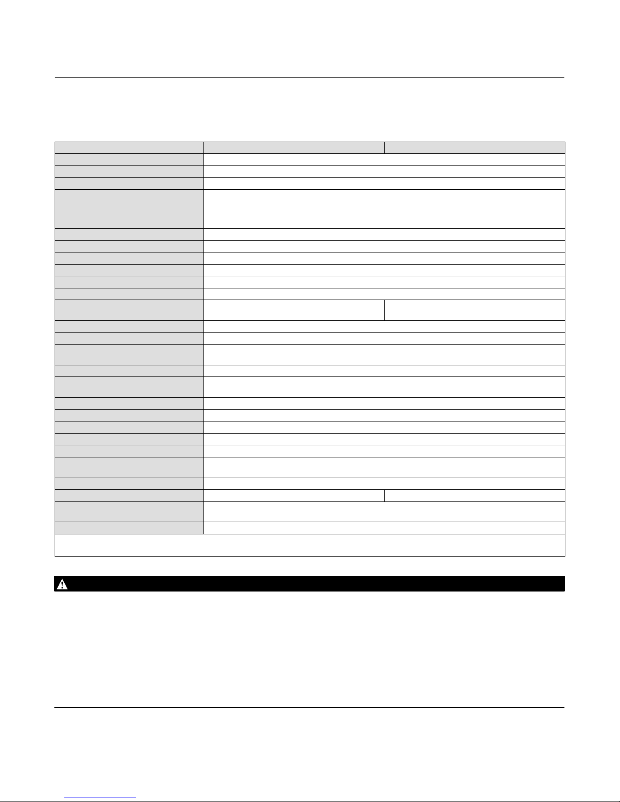
Actuator Specifications
Table 1. CML Actuator Specifications
ACTUATOR CML-250 CML-750
ACTUATOR HOUSING Cast Aluminum
ENVIRONMENTAL RATINGS FM, CSA, ATEX, IEC
OPTIONAL RATINGS FM, CSA, ATEX, IEC
FM
STANDARD ENCLOSURE
STANDARD TEMPERATURE RATING -30°C to +70°C (-22°F to +158°F)
HAZAROUS AREA TEMPERATURE RANGE -20°C to +65°C (-4°F to +150°F)
CONDUIT CONNECTION 3/4" - 14 NPT (M25 x 1.50p optional)
MOTOR TYPE Brushless DC
OPTIONAL VOLTAGES 120VAC, 240VAC, 24VDC
STANDARD POWER 120VAC/240VAC
THRUST RATING
THRUST ADJUSTABILITY 60% - 150% Rated Thrust
MAX SPEED 0.13 in/sec
STANDARD CONTROL
STANDARD FEEDBACK 4-20mA loop powered feedback
STANDARD CONTROL OPTIONS
(SPECIAL)
HMI/GUI SETUP LCD - text
MODULATING DUTY CYCLE Unrestricted and Continuous
RESOLUTION 0.2% (adjustable deadband 0 - 10% of analogue signal)
SENSITIVITY 0.2%
RESPONSE TIME 20 milliseconds
STANDARD FAILURE ACTION
CUSTOMER SETTINGS SAVED Yes, Standard
WEIGHT (ACTUATOR ONLY) 8.3 kg (18.4 lbs) 11.5 kg (25.4 lbs)
POWER BACK-UP OPTION
LOWER CONTROL OPTION Available: Separate option. Local controls come standard with Super Capacitor Power Back-up
1. 24VAC not available.
2. Adjustable from 50 to 100%.
3. Includes 2 adjustable relay outputs.
250 lbs Mod/Run (1112.1 N)
375 lbs Seating (1668.1 N)
Full range 4-20mA / Split Range 4/12 or 12-20mA
Discrete On/Off RIRO [24VDC or 120VAC control], HART, Foundation
Fieldbus, DeviceNet, Profibus, Modbus, Pakscan
Close valve / Open valve / Hold-in-Place / Fail to Position on loss of input signal (selectable).
Holds in place on power failure (standard)
Available: Super Capacitors. Fail to Position on Loss of Power.
Adjustable to Fail Closed, Fail Open, Fail to Position, Fail in Place
NEMA 4 and 6 / IP67
Class 1 Div 1 Gr C, D
Class II Div I E, F, G
(1)
750 lbs Mod/Run (3336.2 N)
1125 lbs Seating (5004.2 N)
(2)
**optional: 0-5Vdc and 0-10Vdc
(3)
WARNING
Always wear protective gloves, clothing and eyewear when performing any installation operations to avoid personal
injury.
Personal injury or property damage caused by sudden release of pressure or bursting of pressure retaining parts may result
if service conditions exceed those for which the product was intended. To avoid injury or damage, provide a relief valve for
over pressure protection as required by government or accepted industry codes and good engineering practices.
Check with your process or safety engineer for any additional measures that must be taken to protect against process
media.
If installing into an existing application, also refer to the WARNING at the beginning of the Maintenance section in this
instruction manual.
2
Page 3

Instruction Manual
D104302X012
CML Electric Actuator
January 2019
CAUTION
This actuator is intended for a specific range of pressures, temperatures and other application specifications. Applying
different pressures and temperatures to the actuator could result in parts damage, malfunction of the actuator or loss of
control of the process. Do not expose this product to service conditions or variables other than those for which the product
was intended. If you are not sure what these conditions are you should contact your Emerson sales office
complete specifications. Provide the product serial numbers (shown on the nameplate) and all other pertinent information.
for more
WARNING
If you move or work on an actuator installed on a valve with loading pressure applied, keep your hands and tools away
from the stem travel path to avoid personal injury. Be especially careful when removing the stem connector to release all
loading on the actuator stem.
Likewise take similar care when adjusting or removing any optional travel stop. Refer to the relevant actuator Maintenance
Instructions.
If hoisting the valve, take care to prevent people from being injured in case the hoist or rigging slips. Be sure to use
adequate sized hoists and chains or slings to handle the valve.
WARNING
Personal injury could result from packing leakage. Valve packing is tightened before shipment; however, the packing
might require some readjustment to meet specific service conditions.
Educational Services
For information on available courses for CML electric actuators, as well as a variety of other products, contact:
Emerson Automation Solutions
Educational Services - Registration
Phone: 1-641-754-3771 or 1-800-338-8158
E-mail: education@emerson.com
emerson.com/fishervalvetraining
3
Page 4

CML Electric Actuator
January 2019
Instruction Manual
D104302X012
Maintenance
WARNING
Avoid personal injury and property damage from sudden release of process pressure or bursting of parts. Before
performing any maintenance operations:
D Do not remove the actuator from the valve while the valve is still pressurized.
D Always wear protective gloves, clothing, and eyewear when performing any maintenance operations.
D Disconnect any operating lines providing air pressure, electric power, or a control signal to the actuator. Be sure the
actuator cannot suddenly open or close the valve.
D Use bypass valves or completely shut off the process to isolate the valve from process pressure. Relieve process pressure
on both sides of the valve. Drain the process media from both sides of the valve.
D Use lock‐out procedures to be sure the above measures stay in effect while you work on the equipment.
D The valve packing box may contain process fluids that are pressurized, even when the valve has been removed from the
pipeline. Process fluids may spray out when removing the packing hardware or packing rings, or when loosening the
packing box pipe plug.
D Check with your process or safety engineer for any additional measures that must be taken to protect against process
media.
Note
It is recommended that you review figure 2 before performing maintenance or installation of the CML electric actuator.
Recommended Installation Location
It is permissible to install the CML actuator upright or horizontally. Allow 12 inches of clearance for removal of the
actuator. Do not install with the actuator below the pipe.
CAUTION
To avoid equipment damage, do not install the valve with the stem in a downward position. Equipment damage may occur
from liquids leaking into the actuator cover.
4
Page 5

Instruction Manual
D104302X012
Figure 2. CML Actuator Components
CML Electric Actuator
January 2019
584
(23)
GE90415
CML-250
729
(28.7)
GE90416
CML-750
Table 2. CML Mounting Parts List
Key No. Description Qty
-- Actuator 1 Consult your Emerson sales office
2 Stem Adaptor 1 NA GE87952X022
3 Nut 2 NA 24334-1
4 Lock Washer 4 NA 20075
5 Cap Screw 4 NA 82813
17 Actuator Yoke 1 24184-3B GE87978X022
56 Travel Scale 1 983674-001-250 NA
68 Spacer 1 24186 GE79905X012
CML 250 CML 750
Part Number Part Number
mm
(Inch)
5
Page 6

CML Electric Actuator
January 2019
Figure 3. Typical Baumann Valve Components
A
Instruction Manual
D104302X012
E1239
Table 3. Common Valve Parts
Key Number Description
1 Valve Body
2 Seat Ring
4 Plug
5 Stem
8 Bonnet
8A Bonnet Bushing
9 Drive Nut
10 Packing Follower
12 O-Ring
14 Packing
27 Lock Nuts
49 Body Gasket
58 Travel Indicator
6
Page 7

Instruction Manual
D104302X012
CML Electric Actuator
January 2019
Installation
See table 2 for actuator parts/key numbers referenced in this Installation section. See table 3 and also refer to the
appropriate Baumann valve instruction manual for valve parts referenced.
1. Before starting, ensure you have the correct actuator part number and locate the parts listed in table 2. Refer to the
assembly instructions for the appropriate Baumann control valve for parts identification.
2. Place the valve body (key1) in a vise. Clamp the flat end faces of the valve. DO NOT CLAMP THE SIDES OF THE
VALVE. This may distort the shape of the casting and ruin the valve.
3. Push the valve stem (key 5) to the closed position. Install the two lock nuts (key 27) onto the stem (key 25).
4. Slowly lower the actuator down on the valve body (key 1). As the yoke (key 17) passes over the end of the valve
stem (key 5), place the yoke drive nut (key 9) over the valve stem (key 5).
5. Screw the yoke drive nut (key 9) on to the bonnet (key 8) and tighten.
6. Place travel indicator disc (key 58) onto the valve stem (key 5).
7. For CML 750: Skip to step 10.
8. For CML 250: Remove the drive nut (supplied with actuator) from the base of the actuator and set the upper drive
nut over the valve stem (key 5).
9. Place the spacer (key 68) on top of the actuator yoke (key 17) over the opening.
10. Set the actuator on top of the actuator yoke (key 17) and prepare for mounting
11. Lift the valve stem (key 5) with the travel indicator (key 58) and hold it. Spin the actuator onto top of the yoke (key
17) to screw the actuator stem onto the valve stem (key 5) by 9 full turns. The actuator should be facing forward
when engagement is complete.
For the CML750 align the four bolt holes in the yoke (key 17) with the bolt holes in the actuator with the actuator
facing forward.
12. For the CML 250 tighten the upper lock nut (supplied with actuator) on the actuator thread.
For the CML750 install the 4 cap screws (key 5) and tighten to 20 ftSlbs.
13. Raise the top lock nut (key 27) and lock travel indicator (key 58) on top. Then raise the lower lock nut (key 27) and
lock in place to secure travel indicator (key 58) tight against the actuator stem.
Additional Calibration and Setup
Additional calibration and setup information is available:
D CMA Installation and Maintenance Manual (PUB094-009
D CMA Range Quick Start Guide (PUB094-007
)
)
7
Page 8

CML Electric Actuator
January 2019
Parts Ordering
Contact your Emerson sales office about this equipment.
Instruction Manual
D104302X012
Neither Emerson, Emerson Automation Solutions, nor any of their affiliated entities assumes responsibility for the selection, use or maintenance
of any product. Responsibility for proper selection, use, and maintenance of any product remains solely with the purchaser and end user.
Baumann and Fisher are marks owned by one of the companies in the Emerson Automation Solutions business unit of Emerson Electric Co. Emerson
Automation Solutions, Emerson, and the Emerson logo are trademarks and service marks of Emerson Electric Co. All other marks are the property of their
respective owners.
The contents of this publication are presented for informational purposes only, and while every effort has been made to ensure their accuracy, they are not
to be construed as warranties or guarantees, express or implied, regarding the products or services described herein or their use or applicability. All sales are
governed by our terms and conditions, which are available upon request. We reserve the right to modify or improve the designs or specifications of such
products at any time without notice.
Emerson Automation Solutions
Marshalltown, Iowa 50158 USA
Sorocaba, 18087 Brazil
Cernay, 68700 France
Dubai, United Arab Emirates
Singapore 128461 Singapore
www.Fisher.com
8
E 2017, 2019 Fisher Controls International LLC. All rights reserved.
 Loading...