

Page 1
Instruction Manual
D103292X012
C1 Controllers and Transmitters
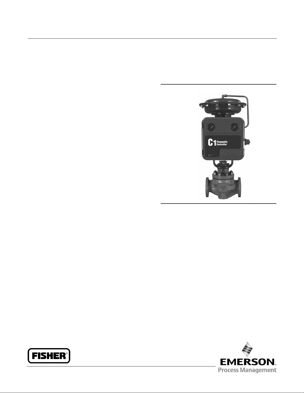
Fisherr C1 Pneumatic Controllers and
Transmitters
May 2014
Contents
Introduction 2.................................
Scope of Manual 2.............................
Description 2.................................
Specifications 2...............................
Educational Services 2.........................
Installation 6..................................
Standard Installation 6.........................
Panel Mounting 7.............................
Wall Mounting 7..............................
Pipestand Mounting 7.........................
Actuator Mounting 7..........................
Pressure Connections 9........................
Supply Pressure 9..........................
Process Pressure 10........................
Vent Assembly 11.............................
Controller Operation 11.........................
Proportional-Only Controllers 11.................
Adjustments 11...........................
Adjustment: Set Point 11.................
Adjustment: Proportional Band 11..........
Calibration: Proportional-Only Controllers 12...
Startup: Proportional-Only Controllers 15......
Proportional-Plus-Reset Controller 15............
Adjustments 16...........................
Adjustment: Set Point 16.................
Adjustment: Proportional Band 16..........
Adjustment: Reset 16....................
Adjustment: Anti-Reset Windup 17.........
Calibration 17.............................
Calibration: Proportional-Plus-Reset
Controllers 17..........................
Calibration: Anti-Reset Windup 19..........
Startup: Proportional-Plus-Reset
Controllers 20..........................
Differential Gap Controllers 20..................
Adjustments 21...........................
Adjustment: Set Point 21.................
Adjustment: Proportional Band 21..........
Calibration: Differential Gap Controllers 21....
Startup: Differential Gap Controllers 23.......
Transmitter Operation 23........................
Adjustments 23...............................
Adjustment: Zero 23.......................
Adjustment: Span 24.......................
Figure 1. Fisher C1 Controller Yoke-Mounted on
Control Valve Actuator
W9263-1
Calibration: Transmitters 24....................
Startup: Transmitters 26.......................
Principle of Operation 27........................
Proportional-Only Controllers 27.................
Proportional-Plus-Reset Controllers 28............
Controllers with Anti-Reset Windup 28............
Differential Gap Controllers 28..................
Transmitters 29...............................
Maintenance 30................................
Replacing Gauges 30...........................
Replacing Bourdon Tube 31.....................
Replacing Bellows Sensing Element 32............
Changing Proportional or Reset Valve 33..........
Changing Anti-Reset Windup Differential
Relief Valve 33..............................
Changing Action 33............................
Proportional-Only to a Differential
Gap Controller 33.......................
Reverse to Direct Action 34..................
Relay Replacement 36.........................
Changing Output Signal Range 37...............
Parts Ordering 40...............................
www.Fisher.com
Page 2

C1 Controllers and Transmitters
May 2014
Instruction Manual
D103292X012
Contents (Continued)
Parts Kits 41...................................
Parts List 41...................................
Common Parts 41.............................
Mounting Parts for Panel, Wall, Pipestand
or Actuator Mounting 50.....................
Introduction
Scope of Manual
This instruction manual provides installation, operating, maintenance, and parts information for the Fisher C1 pressure
controllers and transmitters shown in figure 1. Refer to separate instruction manuals for information regarding the
control valve, actuator, and accessories.
Do not install, operate, or maintain C1 pressure controllers and transmitters without first being fully trained and
qualified in valve, actuator, and accessory installation, operation, and maintenance. To avoid personal injury and
property damage, it is important to carefully read, understand, and follow all the contents of this manual, including all
safety cautions and warnings. If you have any questions about these instructions, contact your Emerson Process
Management sales office before proceeding.
Description
The C1 pneumatic pressure controllers and transmitters use a bellows or Bourdon tube sensing element to sense the
gauge pressure, vacuum, compound pressure, or differential pressure of a liquid or gas. The controller or transmitter
output is a pneumatic pressure signal that can be used to operate a final control element, indicating device, or
recording device.
Unless otherwise noted, all NACE references are to NACE MR0175 / ISO15156 & NACE MR0103.
Specifications
Specifications for the C1 controllers and transmitters are listed in table 1. Table 2 explains available configurations and
options.
Educational Services
For information on available courses for C1 controllers and transmitters, as well as a variety of other products, contact:
Emerson Process Management
Educational Services - Registration
Phone: +1-641-754-3771 or +1-800-338-8158
e-mail: education@emerson.com
http://www.emersonprocess.com/education
2
Page 3

Instruction Manual
D103292X012
Table 1. Specifications
C1 Controllers and Transmitters
May 2014
Available Configurations
See table 2
Input Signal
Type: J Gauge pressure, J vacuum, J compound
pressure, or J differential pressure of a liquid or gas
Limits: See table 3 or 4
Output Signal
Proportional-Only or Proportional-Plus-Reset
Controllers and Transmitters:
J 0.2 to 1.0 bar (3 to 15 psig) or
J 0.4 to 2.0 bar (6 to 30 psig) pneumatic pressure
signal
Differential Gap Controllers:
J 0 and 1.4 bar (0 and 20 psig) or
J 0 and 2.4 bar (0 and 35 psig) pneumatic pressure
signal
Action: Control action is field reversible between
J direct (increasing sensed pressure produces
increasing output signal) and J reverse (increasing
sensed pressure produces decreasing output signal).
Supply Pressure Requirements
(1)
See table 5
Supply and Output Connections
1/4 NPT internal
Common Signal Pressure Conversions
See table 6
Proportional Band Adjustment
For Proportional-Only Controllers: Full output
pressure change adjustable from J 2% to 100% of the
sensing element range for 0.2 to 1.0 bar (3 to 15 psig)
or J 4% to 100% of the sensing element range for 0.4
to 2.0 bar (6 to 30 psig)
For Proportional-Plus-Reset Controllers: Full output
pressure change adjustable from J 3% to 100% of the
sensing element range for 0.2 to 1.0 bar (3 to 15
psig), or J 6% to 100% of the sensing element range
for 0.4 to 2.0 bar (6 to 30 psig)
Differential Gap Adjustment
For Differential Gap Controllers:
Full output pressure change adjustable from
15% to 100% of sensing element range
Reset Adjustment
For Proportional-Plus-Reset Controllers: Adjustable
from 0.01 to 74 minutes per repeat (100 to 0.01
repeats per minute)
Supply Pressure Medium
Air or natural gas
Air: Supply pressure must be clean, dry air that meets
the requirements of ISA Standard 7.0.01. A maximum
40 micrometer particle size in the air system is
acceptable. Further filtration down to 5 micrometer
particle size is recommended. Lubricant content is
not to exceed 1 ppm weight (w/w) or volume (v/v)
basis. Condensation in the air supply should be
minimized
Natural Gas: Natural gas must be clean, dry, oil-free,
and noncorrosive. H
S content should not exceed 20
2
ppm.
Steady-State Air Consumption
(2)(3)
0.2 to 1.0 bar (3 to 15 psig): 0.08 normal m3/hour
(3 scfh)
0.4 to 2.0 bar (6 to 30 psig): 0.12 normal m
3
/hour
(4.5 scfh)
−continued−
Zero Adjustment (Transmitters Only)
Continuously adjustable to position span of less than
100% anywhere within the sensing element range
Span Adjustment (Transmitters Only)
Full output pressure change adjustable from 6 to
100% of sensing element range
Performance
Repeatability: 0.5% of sensing element range
Deadband (Except Differential Gap Controllers)
(4)
0.1% of sensing element range
Typical Frequency Response at 100% Proportional
Band
Output to Actuator: 0.7 Hz and 110 degree phase shift
with 1850 cm
3
(113 inches3) volume, actuator at
mid-stroke
Output to Positioner Bellows: 9 Hz and 130 degree
phase shift with 0.2 to 1.0 bar (3 to 15 psig) output to
3
33 cm
(2 inches3) bellows
:
3
Page 4
C1 Controllers and Transmitters
May 2014
Table 1. Specifications (continued)
Instruction Manual
D103292X012
Ambient Operating Temperature Limits
(1)
J Standard Construction: -40 to 71_C (-40 to 160_F)
J High Temperature Construction: -18 to 104_C
(0 to 220_F)
Anti-reset windup (differential pressure relief) and
process pressure gauge options are only available in
the standard construction
If the process temperature is outside the ambient
operating range of the controller, the length of the
capillary tube run from the sensor point to the
controller process input may be adjusted to protect
the controller from the process temperature
Typical Ambient Temperature Operating Influence
Proportional Control only:
$3.0% of output span for each 28_C (50_F) change in
temperature between -40 and 71_C (-40 and 160_F)
for a controller set at 100% proportional band
Proportional-Plus-Reset Control:
$2.0% of output span for each 28_C (50_F) change in
temperature between -40 and 71_C (-40 and 160_F)
for a controller set at 100% proportional band
Transmitters only:
$3.0% of output span for each 28_C (50_F) change in
temperature between -40 and 71_C (-40 and 160_F)
for a transmitter set at 100% span
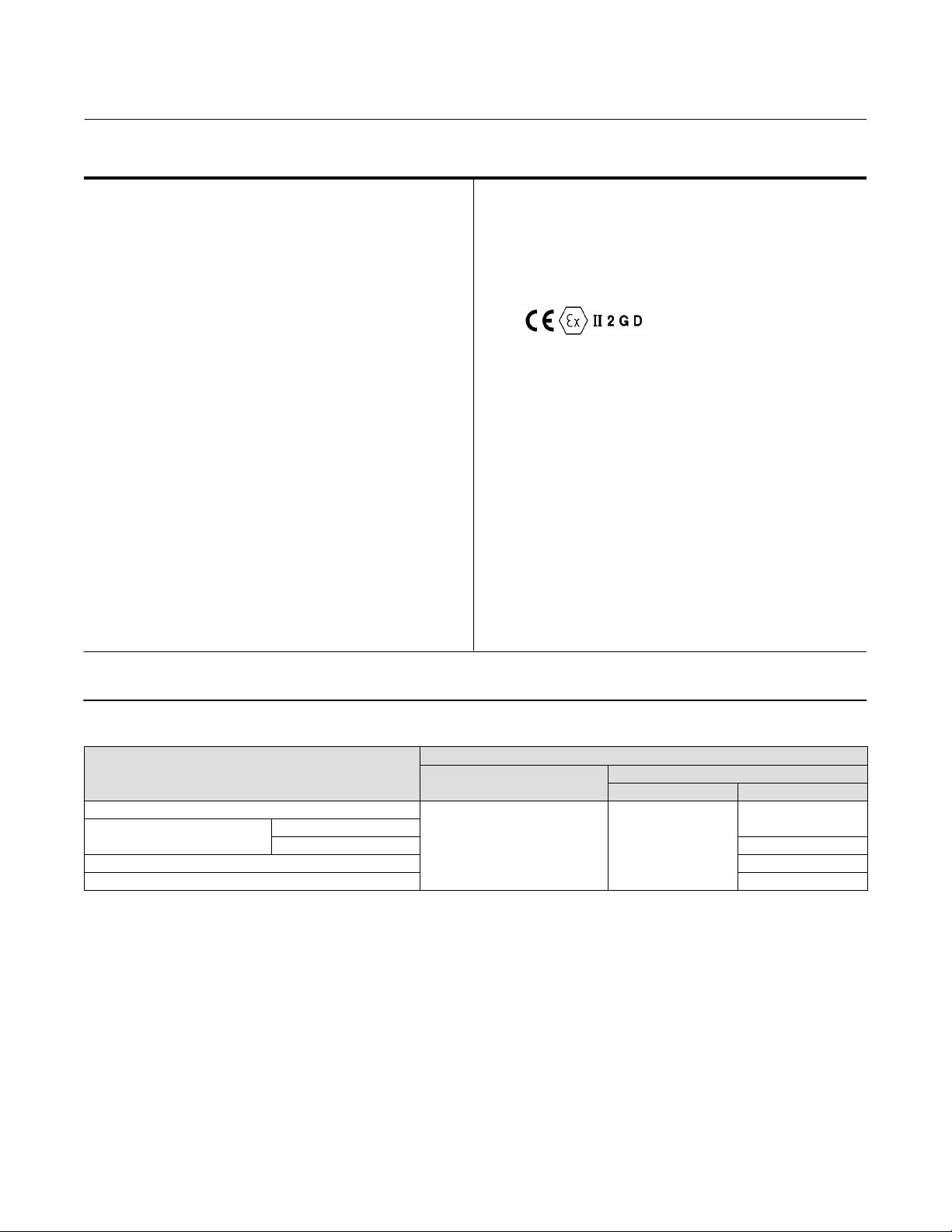
Hazardous Area Classification
Complies with the requirements of ATEX Group II
Category 2 Gas and Dust
Refer to figure 26 for location of ATEX marking
Approximate Weight
8.2 kg (18 pounds)
Declaration of SEP
Fisher Controls International LLC declares this
product to be in compliance with Article 3 paragraph
3 of the Pressure Equipment Directive (PED) 97 / 23 /
EC. It was designed and manufactured in accordance
with Sound Engineering Practice (SEP) and cannot
bear the CE marking related to PED compliance.
However, the product may bear the CE marking to
indicate compliance with other applicable European
Community Directives.
1. The pressure/temperature limits in this document and any applicable standard or code limitation should not be exceeded.
2. Normal m
3. To convert from air flow rate to natural gas flow rate multiply by 1.29.
4. An adjustable differential gap (differential gap controllers) is equivalent to an adjustable deadband.
3
/hr: normal cubic meters per hour (m3/hr, 0_C and 1.01325 bar, absolute). Scfh: standard cubic feet per hour (ft3/hr, 60_F and 14.7 psig).
Table 2. Available Configurations
DESCRIPTION
Proportional-only controller
Proportional-plus-reset controller
Differential gap controller - - -
Transmitter C1D
Without anti-reset windup
With anti-reset windup - - -
Bourdon Tube Sensing Element
(Gauge Pressure Only)
C1P C1B
TYPE NUMBER
Bellows Sensing Element
Gauge Pressure Differential Pressure
C1D
4
Page 5
Instruction Manual
D103292X012
C1 Controllers and Transmitters
May 2014
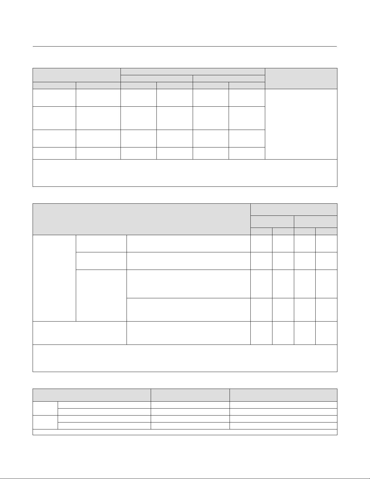
Table 3. Bourdon Tube Pressure Range and Materials
PRESSURE RANGES
(1,2)
MAXIMUM ALLOWABLE STATIC PRESSURE LIMITS
Standard With Optional Travel Stop
Bar Psig Bar Psig Bar Psig
0 to 2.0
0 to 4.0
0 to 7.0
0 to 14
0 to 20
0 to 40
0 to 70
0 to 100
0 to 200
0 to 350
0 to 550
0 to 700
1. If the process can trip to a pressure outside of the operating range of the sensing element, a commercially available device, such as an overpressure protector, may be used to protect
against pressure surges and pulsations.
2. Range marked on Bourdon tube may be in kPa (1 bar = 100 kPa)
3. Bourdon tube may be pressurized to limit shown without permanent zero shift.
4. With travel stop set at 110% of the range.
5. Bourdon tubes are also available in NACE compliant material. Contact your Emerson Process Management sales office for additional information.
0 to 30
0 to 60
0 to 100
0 to 200
0 to 300
0 to 600
0 to 1000
0 to 1500
0 to 3000
0 to 5000
0 to 8000
0 to 10.000
2.0
4.0
7.0
14
20
40
70
100
200
350
550
700
30
60
100
200
300
600
1000
1500
3000
5000
8000
10,000
3.3
6.6
11
19
29
50
83
115
230
380
550
700
(3)
48
96
160
280
420
720
1200
1650
3300
5500
8000
10,000
(4)
MATERIAL
(5)
316 stainless steel
Table 4. Bellows Pressure Ranges and Materials
MAXIMUM ALLOWABLE STATIC
PRESSURE LIMITS
PRESSURE RANGES
(1)
Brass
Construction
Bar Psig Bar Psig
Vacuum
0 to 340 mbar (0 to 10 inch Hg)
0 to 1.0 bar (0 to 30 inch Hg)
75 mbar vac. to 75 mbar (30 inch wc vac. to 30 inch wc)
0 to 150 mbar (0 to 60 inch wc)
Compound Pressure
500 mbar vac. to 500 mbar (15 inch Hg vac. to 7.5 psig)
1.0 bar vac. to 1.0 bar (30 inch Hg vac. to 15 psig)
Gauge Pressure
0 to 150 mbar (0 to 60 inch wc)
0 to 250 mbar
0 to 350 mbar
(3)
(0 to 100 inch wc)
(4)
(0 to 140 inch wc)
0 to 0.35 bar (0 to 5 psig)
Positive pressure
0 to 0.5 bar (0 to 7.5 psig)
0 to 0.7 bar (0 to 10 psig)
0 to 1.0 bar (0 to 15 psig)
0 to 1.4 bar (0 to 20 psig)
0 to 2.0 bar (0 to 30 psig)
0 to 300 mbar (0 to 80 inch wc)
Differential Pressure
(5)
0 to 0.7 bar (0 to 10 psi)
0 to 1.4 bar (0 to 20 psi)
0 to 2.0 bar (0 to 30 psi)
1. If the process can trip to a pressure outside of the operating range of the sensing element, a commercially available device, such as an overpressure protector, may be used to protect
against pressure surges and pulsations.
2. Bellows may be pressured to limit shown without permanent zero shift.
3. Transmitter only.
4. Except transmitter.
5. The overrange limit for these sensing elements is a differential pressure equal to the maximum allowable static pressure limit.
1.4
2.8
2.8
1.4
2.8
2.8
1.4
1.4
2.8
2.8
2.8
2.8
2.8
2.8
2.8
1.4
2.8
2.8
---
20
40
40
20
40
40
20
20
40
40
40
40
40
40
40
20
40
40
---
(2)
Stainless Steel
Construction
---
---
6.9
---
6.9
6.9
---
---
---
---
---
---
6.9
---
6.9
---
---
---
6.9
---
---
100
--100
100
---
---
---
---
---
--100
--100
---
---
--100
Table 5. Supply Pressure Requirements
Output Signal Range
Bar
Psig
1. If this pressure is exceeded, control may be impaired.
0.2 to 1.0 or 0 and 1.4 (differential gap) 1.4 2.8
0.4 to 2.0 or 0 and 2.4 (differential gap) 2.4 2.8
3 to 15 or 0 and 20 (differential gap) 20 40
6 to 30 or 0 and 35 (differential gap) 35 40
Normal Operating Supply
Pressure
(1)
Maximum Allowable Supply Pressure To Prevent
Internal Part Damage
5
Page 6
C1 Controllers and Transmitters
May 2014
Instruction Manual
D103292X012
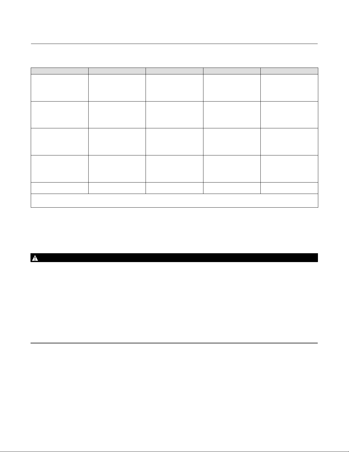
Table 6. Common Signal Pressure Conversions
0.2
0.3
0.4
0.5
0.6
0.8
0.8
1.0
1.0
1.3
1.4
1.5
1.8
1.9
2.0
2.2
2.3
2.5
3.5
5.6
7.0
10.5
2
(3)
Mps kg/cm
0.02
0.03
0.04
0.05
0.06
0.07
0.08
0.09
0.10
0.12
0.14
0.15
0.17
0.18
0.20
0.22
0.23
0.24
0.34
0.55
0.69
1.03
1. Values as listed in ANSI/S7.4.
2. Values as listed in IEC Standard 382.
3. Values rounded to correspond with kPa values.
bar kPa Psi
0.2
0.3
0.4
0.5
0.6
0.8
0.8
1.0
1.0
1.2
1.4
1.5
1.7
1.9
2.0
2.2
2.3
2.4
3.4
5.5
6.9
10.3
(2)
(2)
(3)
20
35
40
50
60
75
80
95
100
125
140
150
170
185
200
220
230
240
345
550
690
1035
(1)
(1)
(1)
(1)
3
5
6
7
9
11
12
14
15
18
20
22
25
27
30
32
33
35
50
80
100
150
Installation
WARNING
To avoid personal injury or property damage resulting from the sudden release of pressure:
D Always wear protective clothing, gloves, and eyewear when performing any installation operations.
D Personal injury or property damage may result from fire or explosion if natural gas is used as the supply medium and
appropriate preventive measures are not taken. Preventive measures may include, but are not limited to, one or more
of the following; remote venting of the unit, re-evaluating the hazardous area classification, ensuring adequate
ventilation, and the removal of any ignition sources. For information on remote venting of this controller/ transmitter,
refer to page 11.
D If installing into an existing application, also refer to the WARNING at the beginning of the Maintenance section in this
instruction manual.
D Check with your process or safety engineer for any additional measures that must be taken to protect against process
media.
Standard Installation
The instruments are normally mounted vertical with the case/cover as shown in figure 1. If installing the instrument in
any other position, be sure that the vent opening shown in figure 2 is facing downward.
6
Page 7

Instruction Manual
D103292X012
C1 Controllers and Transmitters
May 2014
Panel Mounting
Refer to figure 2.
Cut a hole in the panel surface according to the dimensions shown in figure 2. Remove the cap screws (key 252),
brackets (key 251), and vent assembly (key 28). Slide the controller or transmitter into the cutout and reattach the
brackets. Tighten the cap screw located in the center of each bracket to draw the case snugly and evenly against the
panel. Reinstall the vent unless a remote vent will be used.
Wall Mounting
Refer to figure 2.
Drill four holes in the wall using the dimensions shown in figure 2. In the bracket (key 251) are 8.7 mm (0.3438 inch)
diameter holes. Back out the cap screw located in the center of each bracket. (The screws are used for panel mounting
but are not required for wall mounting.) If tubing runs through the wall, drill holes in the wall to accommodate the
tubings. Figure 2 shows the pressure connection locations in the back of the case.
Mount the controller to the bracket using the four cap screws (key 252) provided. Attach the bracket to the wall, using
suitable screws or bolts.
Pipestand Mounting
Refer to figure 2.
Use a hammer and punch to knock out the blanks in the two holes indicated in the back view of figure 2. Attach the
spacer spools (key 228) and the mounting plate (key 213) to the controller with cap screws, lock washers, and nuts
(keys 215, 221, and 216). Attach the controller to a 2-inch (nominal) pipe with pipe clamps (key 250).
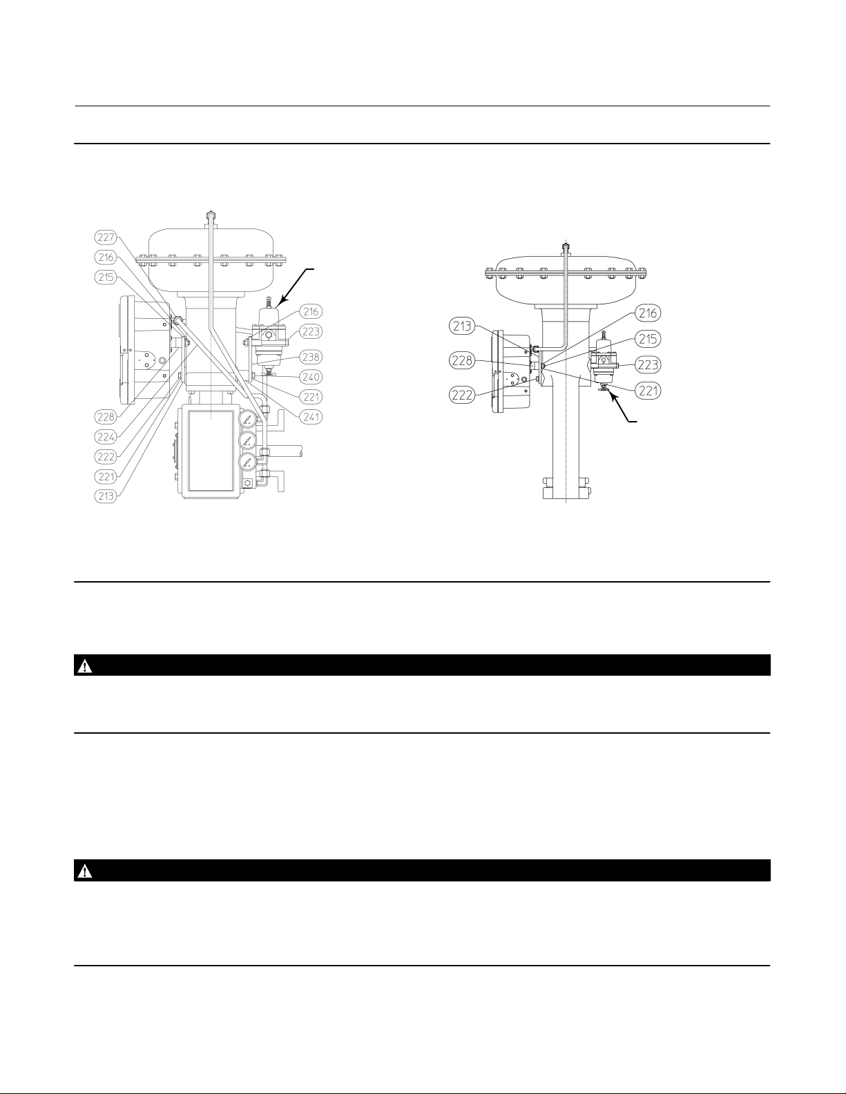
Actuator Mounting
Refer to figure 3.
Controllers specified for mounting on a control valve actuator are mounted at the factory. If the instrument is ordered
separately for installation on a control valve actuator, mount the instrument according to the following instructions.
Mounting parts for the different actuator types and sizes vary. Two typical actuator-mounting installations are shown
in figure 3; see the parts list for parts required for the specific actuator type and size involved.
Use a hammer and punch to knock out the blanks in the two holes indicated in the back view of figure 2. Attach the
spacer spools (key 228) and the mounting plate (key 213) to the controller with machine screws, lock washers, and
nuts (keys 215, 221, and 216).
Attach the mounting bracket to the actuator yoke with cap screws (key 222) and, if needed, spacer spools. On some
designs, the mounting bracket is attached to the actuator diaphragm casing rather than to the yoke.
7
Page 8

C1 Controllers and Transmitters
May 2014
Figure 2. Panel, Wall, and Pipestand Mounting
180.8
(7.12)
2 INCH
(NOMINAL)
PIPE
65.8
(2.59)
23.1
(0.91)
63.5
(2.50)
Instruction Manual
D103292X012
63.5
(2.50)
VENT ASSEMBLY
(KEY 28)
PIPESTAND MOUNTING
8.7
(11/32)
MOUNTING
HOLES
PANEL MOUNTING WALL MOUNTING
NOTES:
1. ALL CONNECTIONS ARE 1/4 NPT INTERNAL.
2
HIGH-PRESSURE CONNECTION FOR DIFFERENTIAL-PRESSURE UNITS.
3
LOW-PRESSURE CONNECTION FOR DIFFERENTIAL-PRESSURE UNITS.
E1052
142.7
(5.62)
KNOCK-OUT
BACK VIEW
218.9
(8.62)
CUTOUT FOR
PANEL MOUNTING
69.1
(2.72)
KNOCK-OUT
244.3
(9.62)
215.9
(8.50)
14.3
(0.56) R
FOUR HOLES
FOR WALL
MOUNTING
101.6
(4.00)
mm
(INCH)
8
Page 9
Instruction Manual
D103292X012
Figure 3. Actuator Mounting
C1 Controllers and Transmitters
May 2014
SUPPLY PRESSURE
REGULATOR
SUPPLY PRESSURE
REGULATOR
GE33947-A
GE33946-A
TYPICAL ROTARY ACTUATOR
TYPICAL SLIDING-STEM ACTUATOR
Pressure Connections
WARNING
To avoid personal injury or property damage resulting from the sudden release of pressure, do not install any system
component where service conditions could exceed the limits given in this manual. Use pressure-relieving devices as
required by government or accepted industry codes and good engineering practices.
All pressure connections on C1 instruments are 1/4 NPT internal. Use 6 mm (1/4-inch) or 10 mm (3/8-inch) pipe or
tubing for supply and output piping. The pressure connection locations are shown in figure 2.
Supply Pressure
WARNING
Severe personal injury or property damage may occur from an uncontrolled process if the instrument supply medium is not
clean, dry, oil-free and noncorrosive. While use and regular maintenance of a filter that removes particles larger than 40
micrometers in diameter will suffice in most applications, check with an Emerson Process Management field office and
industry instrument supply medium quality standards for use with hazardous gas or if you are unsure about the proper
amount or method of air filtration or filter maintenance.
9
Page 10

C1 Controllers and Transmitters
May 2014
Instruction Manual
D103292X012
Supply pressure must be clean, dry air that meets the requirements of ISA Standard 7.0.01. A maximum 40
micrometer particle size in the air system is acceptable. Further filtration down to 5 micrometer particle size is
recommended. Lubricant content is not to exceed 1 ppm weight (w/w) or volume (v/v) basis. Condensation in the air
supply should be minimized. Alternatively, natural gas may be used as the supply pressure medium. Gas must be
clean, dry, oil-free, and noncorrosive. H
S content should not exceed 20 ppm.
2
Use a suitable supply pressure regulator to reduce the supply pressure source to the normal operating supply pressure
shown in table 5. Connect supply pressure to the SUPPLY connection at the back of the case.
WARNING
To avoid personal injury or property damage resulting from the sudden release of process pressure, use a high pressure
regulator system when operating the controller or transmitter from a high pressure source.
If operating the controller or transmitter from a high pressure source [up to 138 bar (2000 psig)], use a high pressure
regulator system, such as the Fisher 1367 High Pressure Instrument Supply System. For 1367 system installation,
adjustment, and maintenance information, refer to the 1367 High-Pressure Instrument Supply System with
Overpressure Protection instruction manual, D100343X012.
Process Pressure
WARNING
To avoid personal injury or property damage resulting from the sudden release of pressure when using corrosive media,
make sure the tubing and instrument components that contact the corrosive medium are of suitable noncorrosive
material.
Also refer to the Installation Warning at the beginning of this section.
The pressure connections to the controller depend upon the type of pressure sensing, gauge or differential. Gauge
pressure controllers use either a Bourdon tube or bellows as the sensing element, as indicated in table 2. Differential
pressure controllers use two bellows to sense differential pressure.
For gauge pressure instruments: The control pressure block (key 10 in figure 22) has two connections. Process
pressure can be connected either to the CONTROL connection on the back of the case, or to the connection on the left
side of the case, shown in figure 2, depending on the instrument application. Plug the unused connection.
For differential pressure instruments: Connect the low pressure line to the CONTROL connection on the side of the
case and the high pressure line to the CONTROL connection on the back of the case as shown in figure 2.
When installing process piping, follow accepted practices to ensure accurate transmission of the process pressure to
the controller or transmitter. Install shutoff valves, vents, drains, or seal systems as needed in the process pressure
lines. If the instrument is located such that the adjacent process pressure lines will be approximately horizontal, the
lines should slope downward to the instrument for liquid-filled lines and upward to instruments for gas-filled lines. This
will minimize the possibility of air becoming trapped in the sensor with liquid-filled lines or of condensation becoming
trapped with gas-filled lines. The recommended slope is 83 mm per meter (1 inch per foot).
If a controller is being used in conjunction with a control valve to control pipeline pressure, connect the process
pressure line in a straight section of pipe approximately 10 pipe diameters from the valve but away from bends,
elbows, and areas of abnormal fluid velocities. For pressure-reducing service, the process line must be connected
downstream of the valve. For pressure-relief service, the process pressure line must be connected upstream of the
control valve. Install a needle valve in the process pressure line to dampen pulsations.
10
Page 11

Instruction Manual
D103292X012
C1 Controllers and Transmitters
May 2014
Vent Assembly
WARNING
Personal injury or property damage could result from fire or explosion of accumulated gas, or from contact with hazardous
gas, if a flammable or hazardous gas is used as the supply pressure medium. Because the instrument case and cover
assembly do not form a gas-tight seal when the assembly is enclosed, a remote vent line, adequate ventilation, and
necessary safety measures should be used to prevent the accumulation of flammable or hazardous gas. However, a remote
vent pipe alone cannot be relied upon to remove all flammable and hazardous gas. Vent line piping should comply with
local and regional codes, and should be be as short as possible with adequate inside diameter and few bends to reduce case
pressure buildup.
CAUTION
When installing a remote vent pipe, take care not to overtighten the pipe in the vent connection. Excessive torque will
damage the threads in the connection.
The vent assembly (key 28, figure 2) or the end of a remote vent pipe must be protected against the entrance of all
foreign matter that could plug the vent. Use 13 mm (1/2-inch) pipe for the remote vent pipe, if one is required. Check
the vent periodically to be certain it has not become plugged.
Controller Operation
Proportional-Only Controllers
This section describes the adjustments and procedures for calibration and startup. Adjustment locations are shown in
figure 4 unless otherwise specified. All adjustments must be made with the cover open. When the adjustments and
calibration procedures are complete, close and latch the cover.
To better understand the adjustments and overall operation of the controller, refer to the Principle of Operation
section in this manual for proportional-only controllers. Refer also to the schematic diagram in figure 13.
Adjustments
Adjustment: Set Point
Adjust the pressure setting knob by turning the knob clockwise to increase the set point and counterclockwise to
decrease the set point. Note that the dial setting and actual process pressure may vary significantly, especially with a
wide proportional band setting.
Adjustment: Proportional Band
To adjust the proportional band, rotate the proportional band adjustment knob to the desired value.
The proportional band adjustment determines the amount of change in controlled pressure required to cause the
control valve to stroke fully. It may be adjusted from 2 to 100 percent for 0.2 to 1.0 bar (3 to 15 psig) or 4 to 100
percent for 0.4 to 2.0 bar (6 to 30 psig) of the nominal sensing element pressure rating.
11
Page 12
C1 Controllers and Transmitters
May 2014
Instruction Manual
D103292X012
Calibration: Proportional-Only Controllers
Unless otherwise indicated, key number locations are shown in figure 4.
Provide a process pressure source capable of simulating the process pressure range of the controller. If an output
pressure gauge is not provided, install a suitable pressure gauge for calibration purposes.
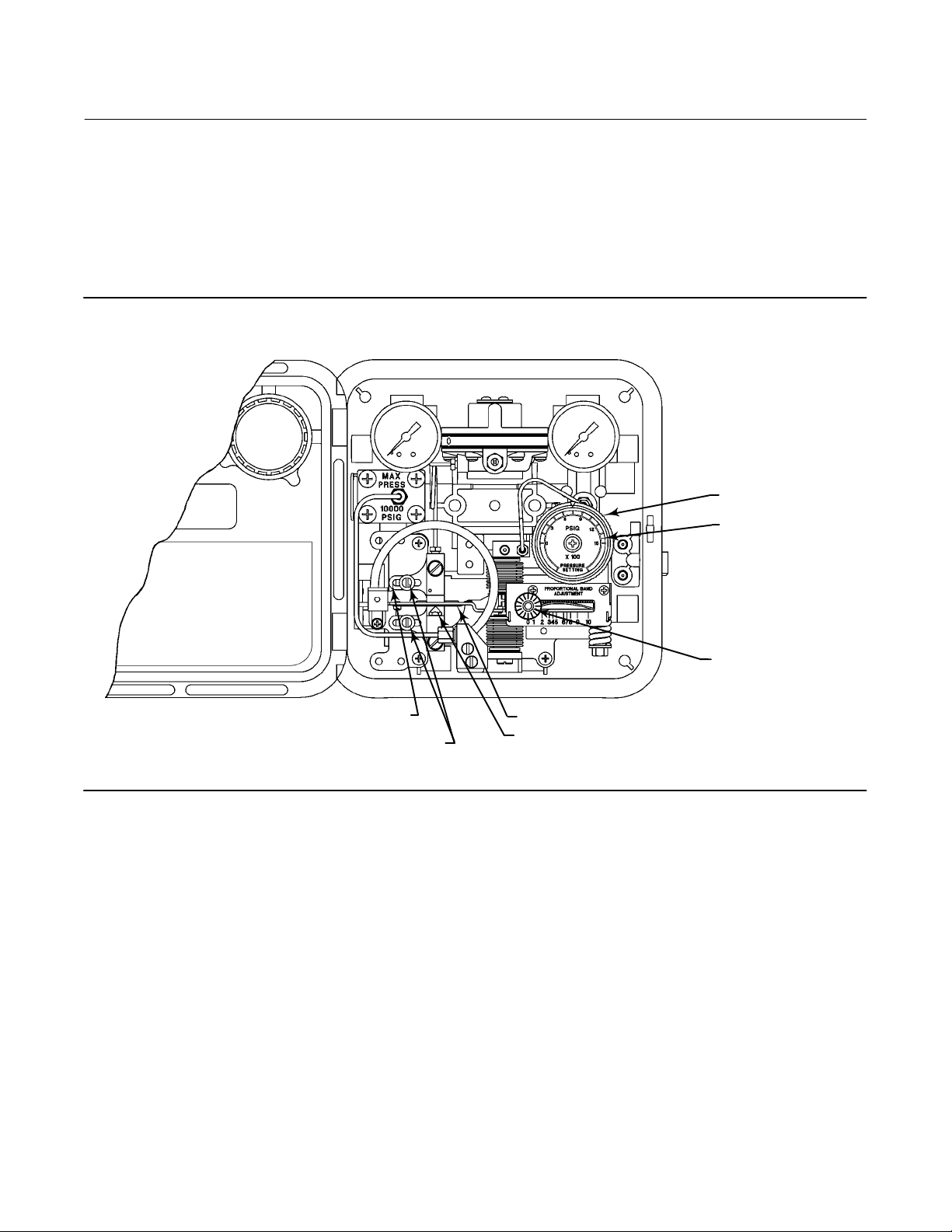
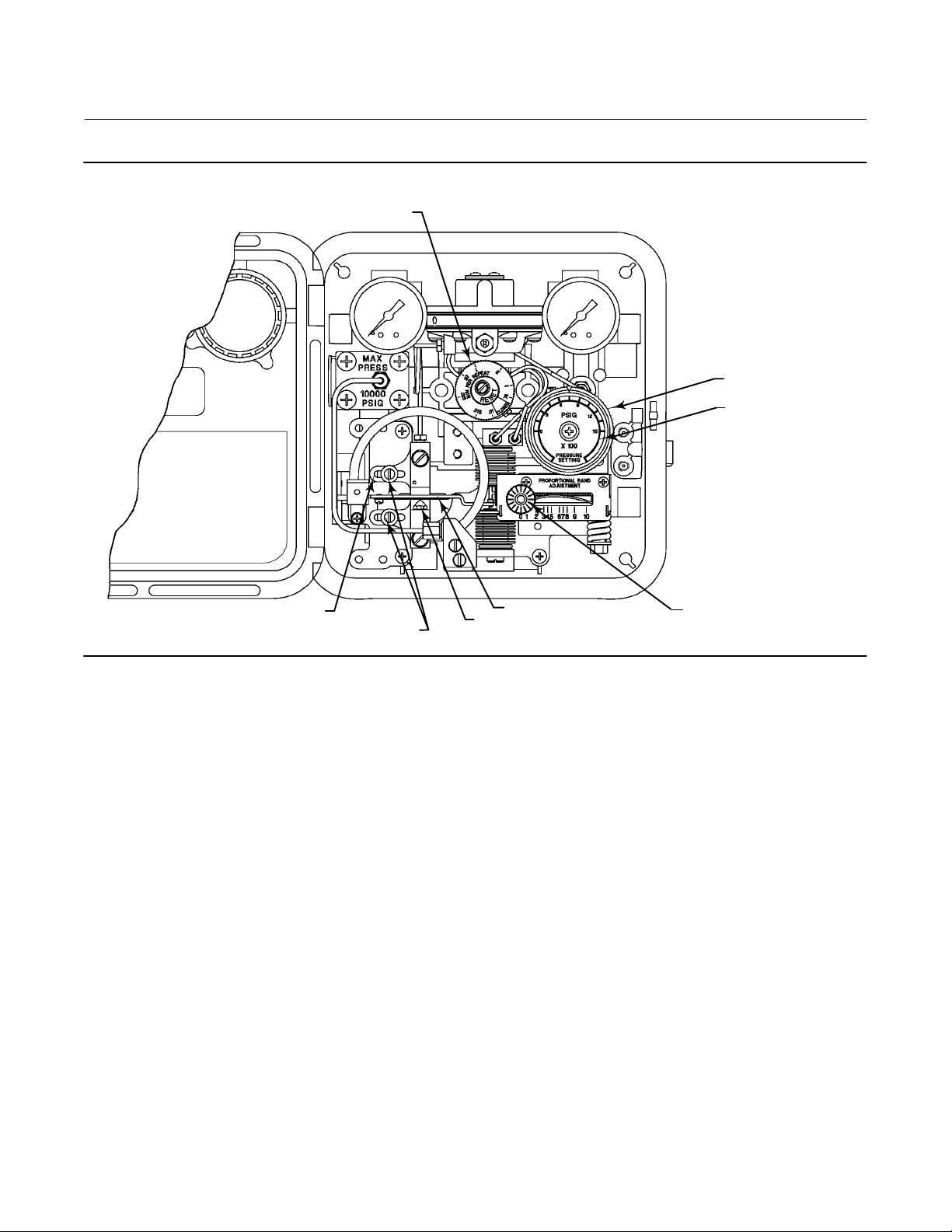
Figure 4. Proportional-Only Controller Adjustment Locations
PRESSURE SETTING KNOB
(KEY 58)
PRESSURE SETTING
DIAL (KEY 6)
PROPORTIONAL BAND
ADJUSTMENT KNOB
GE28280-B
E1059
CALIBRATION ADJUSTER (KEY 36)
ADJUSTER SCREWS (KEY 48)
FLAPPER (KEY 40)
NOZZLE (KEY 54)
Connect a pressure source to the supply pressure regulator and be sure the regulator is delivering the correct supply
pressure to the controller. The controller must be connected open loop (Open loop: The controller output pressure
changes must be dead ended into a pressure gauge). The following procedures use a 0.2 to 1.0 bar (3 to 15 psig)
output pressure range as an example. For a 0.4 to 2.0 bar (6 to 30 psig) output range, adjust the values as appropriate.
1. Complete the above connections and provide a process pressure equal to the sensing element range.
2. Rotate the proportional band adjustment knob, shown in figure 4, to 1.5 (15 percent proportional band).
3. Verify that the calibration adjuster screws (key 48) are at mid-position in the calibration adjuster (key 36) slots.
Depending upon the controller action, perform one or the other of the following procedures.
12
Page 13
Instruction Manual
D103292X012
C1 Controllers and Transmitters
May 2014
For reverse-acting controllers:
4. Apply an input pressure equal to the sensing element upper range value.
5. Rotate the pressure setting knob to the maximum value.
6. Adjust the nozzle (key 54) until the controller output pressure is between 0.6 and 0.7 bar (8 and 10 psig).
7. Apply an input pressure equal to the sensing element lower range value.
8. Rotate the pressure setting knob to the minimum value.
Note
When performing the span adjustment in step 9, do not watch the output gauge while changing the calibration adjuster. The
change in output is not a good indication of the change in span. While moving the calibration adjuster, the output pressure may
change in the opposite direction than expected. For example, while moving the calibration adjuster to increase span, the output
pressure may decrease. This should be disregarded since even though the output pressure decreases, the span is increasing.
Proper controller response depends on nozzle-to-flapper alignment.
When performing span adjustments, carefully loosen both calibration adjuster screws while holding the calibration adjuster in
place. Then move the calibration adjuster slightly in the required direction by hand or using a screwdriver. Verify proper
nozzle-to-flapper alignment and hold the calibration adjuster in place while tightening both adjustment screws.
9. If the output is not between 0.6 and 0.7 bar (8 and 10 psig), adjust the controller span by loosening the two
adjusting screws (key 48) and moving the calibration adjuster (key 36) a small distance as indicated in figure 5.
10. Repeat steps 4 through 9 until no further adjustment is necessary.
11. Proceed to the startup procedure for proportional controllers.
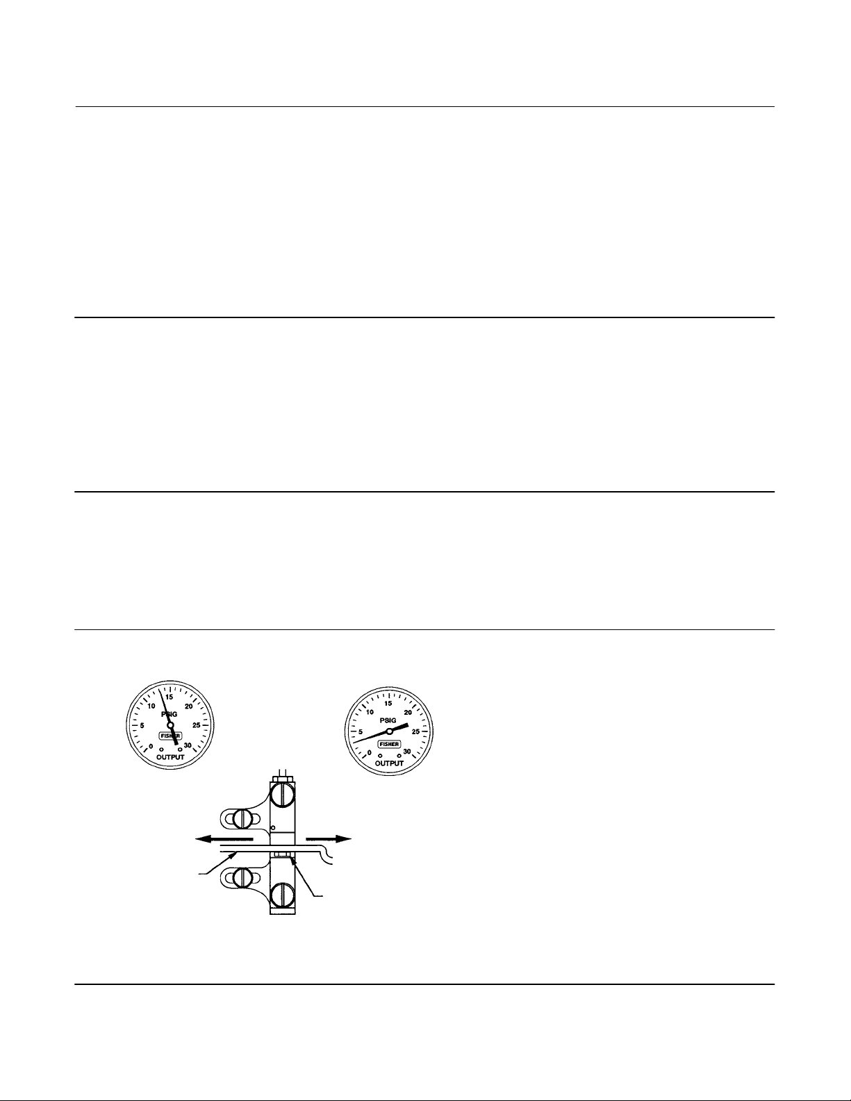
Figure 5. Reverse-Acting Controller Span Adjustment — Proportional-Only Controllers
IF OUTPUT IS:
ABOVE
8 TO 10 PSIG
(0.6 TO 0.7 BAR)
MOVE ADJUSTER
NOTE:
3 TO 15 PSIG (0.2 TO 1.0 BAR) OUTPUT SHOWN.
FOR 6 TO 30 PSIG (0.4 TO 2.0 BAR) OUTPUT, ADJUST
VALUES AS APPROPRIATE.
A6155-1
LEFT
FLAPPER
NOZZLE
BELOW
8 TO 10 PSIG
(0.6 TO 0.7 BAR)
MOVE ADJUSTER
RIGHT
13
Page 14
C1 Controllers and Transmitters
May 2014
Instruction Manual
D103292X012
For direct-acting controllers:
4. Apply an input pressure equal to the sensing element lower range value.
5. Rotate the pressure setting knob to the minimum value.
6. Adjust the nozzle (key 54) until the controller output pressure is between 0.6 and 0.7 bar (8 and 10 psig.)
7. Apply an input pressure equal to the sensing element upper range value.
8. Rotate the pressure setting knob to the maximum value.
Note
When performing the span adjustment in step 9, do not watch the output gauge while changing the calibration adjuster. The
change in output is not a good indication of the change in span. While moving the calibration adjuster, the output pressure may
change in the opposite direction than expected. For example, while moving the calibration adjuster to increase span, the output
pressure may decrease. This should be disregarded since even though the output pressure decreases, the span is increasing.
Proper controller response depends on nozzle-to-flapper alignment.
When performing span adjustments, carefully loosen both calibration adjuster screws while holding the calibration adjuster in
place. Then move the calibration adjuster slightly in the required direction by hand or using a screwdriver. Verify proper
nozzle-to-flapper alignment and hold the calibration adjuster in place while tightening both adjustment screws.
9. If the output is not between 0.6 and 0.7 bar (8 and 10 psig), adjust the controller span by loosening the two
adjusting screws (key 48) and moving the calibration adjuster (key 36) a small distance as indicated in figure 6.
10. Repeat steps 4 through 9 until no further adjustment is necessary.
11. Proceed to the startup procedure for proportional controllers.
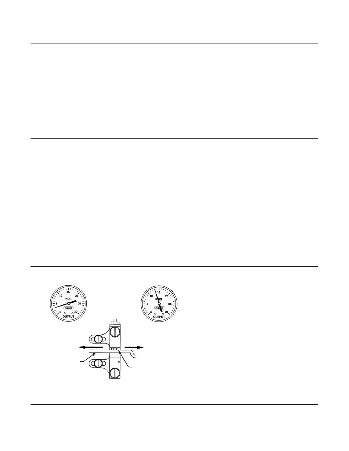
Figure 6. Direct-Acting Controller Span Adjustment—Proportional-Only Controllers
IF OUTPUT IS:
BELOW
8 TO 10 PSIG
(0.6 TO 0.7 BAR)
MOVE ADJUSTER
NOTE:
3 TO 15 PSIG (0.2 TO 1.0 BAR) OUTPUT SHOWN.
FOR 6 TO 30 PSIG (0.4 TO 2.0 BAR) OUTPUT, ADJUST
VALUES AS APPROPRIATE.
A6154
LEFT
FLAPPER
NOZZLE
ABOVE
8 TO 10 PSIG
(0.6 TO 0.7 BAR)
MOVE ADJUSTER
RIGHT
14
Page 15

Instruction Manual
D103292X012
C1 Controllers and Transmitters
May 2014
Startup: Proportional-Only Controllers (General Tuning Guidelines)
Calibrate the controller prior to this procedure.
1. Be sure that the supply pressure regulator is delivering the proper supply pressure to the controller.
2. Rotate the pressure setting knob to the desired set point.
3. Set the proportional band adjustment to 100 percent for fast processes (example: liquid pressure or liquid flow). For
slow processes (example: temperature), calculate the percentage from the equation below:
For a slow process, determine the initial proportional band setting in percent from the following equation:
2 AllowableOvershoot
PressureSpan
For example:
2 0.14bar
2.1bar
2 2psig
(
30psig
1.3 proportional band setting
4. Proportional Action
Disturb the system by tapping the flapper lightly or change the set point a small amount and check for system cycling.
If the system does not cycle then lower the proportional band (raising the gain) and disturb the system again.
Continue this procedure until the system cycles. At that point, double the proportional band setting.
Note
Proportional band adjustment affects the set point. Proportional-only controllers will show some offset from set point depending
upon proportional band setting and process demand. After adjusting the proportional band, re-zero by carefully rotating the
nozzle (key 54) until the steady-state process pressure equals the pressure setting dial reading.
100% ^ 13%
100% ^ 13%
100% + P.B.
)
This tuning procedure may be too conservative for some systems. The recommended proportional band setting
should be checked for stability by introducing a disturbance and monitoring the process.
Proportional-Plus-Reset Controllers
This section describes the adjustments and procedures for calibration and startup. The adjustment locations are
shown in figure 7 unless otherwise specified. All adjustments must be made with the cover open. When the
adjustments and calibration procedures are complete, close and latch the cover. To better understand the
adjustments and overall operation of the controller, refer to the Principle of Operation section in this manual for
proportional-plus-reset controllers. Refer also to the schematic diagram in figure 13.
15
Page 16
C1 Controllers and Transmitters
May 2014
Figure 7. Proportional-Plus-Reset Controller Adjustment Locations
RESET ADJUSTMENT KNOB
Instruction Manual
D103292X012
PRESSURE SETTING KNOB
(KEY 58)
PRESSURE SETTING
DIAL (KEY 6)
GE28281-B
E1060
CALIBRATION ADJUSTER (KEY 36)
ADJUSTER SCREWS (KEY 48)
FLAPPER (KEY 40)
NOZZLE (KEY 54)
PROPORTIONAL BAND
ADJUSTMENT KNOB
Adjustments
Adjustment: Set Point
Adjust the pressure setting knob by turning the knob clockwise to increase the set point and counterclockwise to
decrease the set point.
Rotate the knob until the indicator points to the desired set point pressure value. The pressure setting dial will reflect
the desired set point if the controller is accurately calibrated.
Adjustment: Proportional Band
To adjust the proportional band, rotate the proportional band adjustment knob to the desired value.
The proportional band adjustment determines the amount of change in controlled pressure required to cause the
control valve to stroke fully. It may be adjusted from 3 to 100 percent for 0.2 to 1.0 bar (3 to 15 psig) or 6 to 100
percent for 0.4 to 2.0 bar (6 to 30 psig) of the nominal sensing element pressure rating.
Adjustment: Reset
To adjust reset action turn the knob clockwise to decrease the minutes per repeat. Turn the knob counterclockwise to
increase the minutes per repeat. Increasing the minutes per repeat provides a slower reset action.
The reset adjustment dial is calibrated in minutes per repeat. By definition, this is the time in minutes required for the
reset action to produce an output change which is equal to the change produced by proportional control action. This is
16
Page 17

Instruction Manual
D103292X012
C1 Controllers and Transmitters
May 2014
in effect, the time in minutes required for the controller to increase (or decrease) its output pressure by an amount
equal to a proportional increase (or decrease) caused by a change in set point or process pressure.
Adjustment: Anti-Reset Windup
The externally mounted differential relief valve can be mounted to relieve on increasing or decreasing output pressure.
Calibration
Calibration: Proportional-Plus-Reset Controllers
Unless otherwise indicated, key number locations are shown in figure 7.
Before starting this procedure:
D Provide a process pressure source capable of simulating the process pressure range of the controller.
D If an output pressure gauge is not provided, install a suitable pressure gauge for calibration purposes. The
controller must be connected open loop (Open loop: The controller output pressure changes must be dead
ended into a pressure gauge).
Note
C1P and C1B controllers with anti-reset windup are supplied with two O-rings (key 81), an anti-reset windup cover (key 80), and
two machine screws (key 82). Use these parts in the next step.
1. For C1P and C1B controllers with anti-reset windup record the direction of the arrow on the anti-reset windup
assembly (key 190, in figure 23). Remove the assembly and install the two O-rings (key 81), and cover (key 80)
supplied with the controller. Secure the cover with the two machine screws (key 82) provided.
2. Connect regulated supply pressure to the controller. Do not exceed the normal operating pressure in table 5.
3. Rotate the reset knob to 0.01 minutes per repeat (fastest setting).
4. Rotate the proportional band adjustment knob to 1.5 (15 percent proportional band).
5. Verify that the calibration adjuster screws (key 48) are at mid-position in the calibration adjuster (key 36) slots.
Depending upon the controller action, perform one or the other of the following procedures.
For reverse-acting controllers:
6. Apply an input pressure equal to the sensing element upper range value.
7. Rotate the pressure setting knob to the maximum value.
8. Adjust the nozzle (key 54) until the controller output pressure is between 0.6 and 0.7 bar (8 and 10 psig).
9. Apply an input pressure equal to the sensing element lower range value.
10. Rotate the pressure setting knob to the minimum value.
Note
When performing the span adjustment in step 11, do not watch the output gauge while changing the calibration adjuster. The
change in output is not a good indication of the change in span. While moving the calibration adjuster, the output pressure may
17
Page 18

C1 Controllers and Transmitters
May 2014
Instruction Manual
D103292X012
change in the opposite direction than expected. For example, while moving the calibration adjuster to increase span, the output
pressure may decrease. This should be disregarded since even though the output pressure decreases, the span is increasing.
Proper controller response depends on nozzle-to-flapper alignment.
When performing span adjustments, carefully loosen both calibration adjuster screws while holding the calibration adjuster in
place. Then move the calibration adjuster slightly in the required direction by hand or using a screwdriver. Verify proper
nozzle-to-flapper alignment and hold the calibration adjuster in place while tightening both adjustment screws.
11. If the output pressure is not between 0.6 and 0.7 bar (8 and 10 psig), adjust the controller span by loosening the
two adjusting screws (key 48) and moving the calibration adjuster (key 36) a small distance as indicated in figure 8.
12. Repeat steps 6 through 11 until no further adjustment is necessary.
13. For C1P and C1B controllers with anti-reset windup, remove the two machine screws, anti-reset windup cover, and
two O-rings installed in step 1 of this procedure. Install the anti-reset windup assembly (key 190) with the arrow
pointing in the direction recorded in step 1.
14. Proceed to the Startup procedures for proportional-plus-reset controllers.
Figure 8. Reverse-Acting Controller Span Adjustment—Proportional-Plus-Reset Controllers
IF OUTPUT IS:
ABOVE
8 TO 10 PSIG
(0.6 TO 0.7 BAR)
MOVE ADJUSTER
NOTE:
3 TO 15 PSIG (0.2 TO 1.0 BAR) OUTPUT SHOWN.
FOR 6 TO 30 PSIG (0.4 TO 2.0 BAR) OUTPUT, ADJUST
VALUES AS APPROPRIATE.
A6155-1
LEFT
FLAPPER
NOZZLE
BELOW
8 TO 10 PSIG
(0.6 TO 0.7 BAR)
MOVE ADJUSTER
RIGHT
For direct-acting controllers:
6. Apply an input pressure equal to the sensing element lower range value.
7. Rotate the pressure setting knob to the minimum value.
8. Adjust the nozzle (key 54) until the controller output pressure is between 0.6 and 0.7 bar (8 and 10 psig).
9. Apply an input pressure equal to the sensing element upper range value.
10. Rotate the pressure setting knob to the maximum value.
Note
When performing the span adjustment in step 11, do not watch the output gauge while changing the calibration adjuster. The
change in output is not a good indication of the change in span. While moving the calibration adjuster, the output pressure may
18
Page 19

Instruction Manual
D103292X012
C1 Controllers and Transmitters
May 2014
change in the opposite direction than expected. For example, while moving the calibration adjuster to increase span, the output
pressure may decrease. This should be disregarded since even though the output pressure decreases, the span is increasing.
Proper controller response depends on nozzle-to-flapper alignment.
When performing span adjustments, carefully loosen both calibration adjuster screws while holding the calibration adjuster in
place. Then move the calibration adjuster slightly in the required direction by hand or using a screwdriver. Verify proper
nozzle-to-flapper alignment and hold the calibration adjuster in place while tightening both adjustment screws.
11. If the output pressure is not between 0.6 and 0.7 bar (8 and 10 psig), adjust the controller span by loosening the
two adjusting screws (key 48) and moving the calibration adjuster (key 36) a small distance as indicated in figure 9.
12. Repeat steps 6 through 11 until no further adjustment is necessary.
13. For C1P and C1B controllers with anti-reset windup remove the two machine screws, anti-reset windup cover, and
two O-rings installed in step 1 of this procedure. Install the anti-reset windup assembly (key 190) with the arrow
pointing in the direction recorded in step 1.
14. Proceed to the Startup procedures for proportional-plus-reset controllers.
Figure 9. Direct-Acting Controller Span Adjustment —Proportional-Plus-Reset Controllers
IF OUTPUT IS:
BELOW
8 TO 10 PSIG
(0.6 TO 0.7 BAR)
MOVE ADJUSTER
NOTE:
3 TO 15 PSIG (0.2 TO 1.0 BAR) OUTPUT SHOWN.
FOR 6 TO 30 PSIG (0.4 TO 2.0 BAR) OUTPUT, ADJUST
VALUES AS APPROPRIATE.
A6154
LEFT
FLAPPER
NOZZLE
ABOVE
8 TO 10 PSIG
(0.6 TO 0.7 BAR)
MOVE ADJUSTER
RIGHT
Calibration: Anti-Reset Windup
Controllers with anti-reset windup have a differential relief valve assembly (figure 23). This relief valve is set at the
factory to relieve at a 0.3 bar (5 psi) pressure difference between the reset bellows pressure and the proportional
bellows pressure. The valve can be adjusted to relieve from 0.14 to 0.4 bar (2 to 7 psig).
The relief valve can relieve on either rising controller output pressure or falling controller output pressure. If the arrow
on the relief valve points toward the bottom of the controller case as shown in figure 23, the valve will relieve on falling
output pressure. If the arrow points in the opposite direction, the valve will relieve on rising output pressure. The valve
can be removed and reinstalled with the arrow pointing in the opposite direction to change the relief action.
19
Page 20

C1 Controllers and Transmitters
May 2014
Instruction Manual
D103292X012
Startup: Proportional-Plus-Reset Controllers (General Tuning Guidelines)
Calibrate the controller prior to this procedure.
1. Be sure that the supply pressure regulator is delivering the proper supply pressure to the controller.
2. Rotate the pressure setting knob to the desired set point.
3. Start with a reset setting of 0.05 minutes per repeat (m/r) for fast processes, and 0.5 m/r for slow processes.
4. Set the proportional band adjustment to 100 percent for fast processes (example: liquid pressure or liquid flow). For
a slow process (example: temperature), calculate the percentage from the equation below:
For a slow process, determine the initial proportional band setting in percent from the following equation:
2 AllowableOvershoot
PressureSpan
For example:
2 0.14bar
2.1bar
2 2psig
()
30psig
1.3 proportional band setting
5. Proportional Action:
Disturb the system by tapping the flapper lightly or change the set point a small amount and check for system cycling.
If the system does not cycle then lower the proportional band (raising the gain) and disturb the system again.
Continue this procedure until the system cycles. At that point, double the proportional band setting and begin tuning
the reset.
6. Reset Action:
Disturb the system. If the system does not cycle then speed up the reset and disturb the system again. Continue this
procedure until the system cycles. When the system cycles multiply the reset time setting by a factor of three (3) and
slow the reset down to the new value. The reset is now tuned.
This tuning procedure may be too conservative for some systems. The recommended proportional band and reset
setting should be checked for stability by introducing a disturbance and monitoring the process as previously
described. For some applications, tighter control may be desirable.
100% ^ 13%
100% ^ 13%
100% + P.B.
Differential Gap Controllers
This section describes the adjustments and procedures for calibration and startup. The adjustment locations are
shown in figure 4 unless otherwise specified. The output of each controller is checked at the factory before the
instrument is shipped.
To convert a differential gap controller to a proportional-only controller or vice versa, refer to the appropriate
procedure in the Maintenance section.
If the process pressure can be varied through all or part of the sensing element range or through the two desired
switching points, use the process pressure for calibration. If not, provide a pressure source to simulate the process
pressure range for calibration procedures.
20
Page 21

Instruction Manual
D103292X012
C1 Controllers and Transmitters
May 2014
To better understand the adjustments and overall operation of the controller, refer to the Principle of Operation
section in this manual for differential gap controllers and the schematic diagram in figure 13.
Adjustments
Adjustment: Set Point
The position of the pressure setting knob determines the location of the differential gap within the range of the
pressure sensing element. Move the pointer to the desired pressure where the output of the controller should switch
from zero to full supply pressure with rising process pressure (direct-acting controllers) or with falling process pressure
(reverse-acting controllers).
Adjustment: Proportional Band
The proportional band adjustment shown in figure 4 determines the width of the differential gap. The width of the gap
is the difference between the process pressures at which the controller output will switch from zero to full supply
pressure, or from full supply pressure to zero. The relationship between the proportional band dial setting and the
differential gap is shown in figure 10.
Figure 10. Differential Gap Adjustment for Differential Gap Controllers
PROPORTIONAL BAND KNOB SETTING
A2202-3
DIFFERENTIAL GAP (PERCENT OF ELEMENT RANGE)
Calibration: Differential Gap Controllers
The output of each controller is checked at the factory before the unit is shipped. Before placing the controller in
control of a process loop, check to verify that the controller is calibrated correctly for the application. The controller
must be connected open loop (Open loop: The controller output pressure changes must be dead ended into a
pressure gauge).
1. Temporarily convert the differential gap controller to proportional-only controller by disconnecting the
proportional tubing (key 25, figure 16) from the mounting base. Reinstall the tubing into the other connection in
the mounting base. Remove the proportional band assembly and invert it as shown in figure 16. Do not invert the
reversing block (key 37, figure 16).
2. Temporarily invert the proportional band assembly (refer to figure 17):
a. Turn the proportional band assembly (key 73) to 10.
b. Unscrew the spring adjustor (key 65), removing the bias spring (key 70) and washers (key 62) with it.
21
Page 22

C1 Controllers and Transmitters
May 2014
c. Unclip the lock spring (key 72). Remove the indicator scale (key 69) and proportional band adjustment knob
(key 73).
d. Remove the gain adjustment bar (key 63). Flip it over so it attaches to the opposite side of the cantilever spring
(key 8) as shown in figure 16 and screw it back down.
e. Flip over the indicator scale (key 69); install it and the proportional band adjustment knob (key 73) as a unit. Snap
in the lock spring (key 72).
f. Tighten down the spring adjustor (key 65) with the bias spring (key 70) and washers (key 62) until it stops against
the gain adjustment bar (key 63).
g. Turn the proportional band adjustment knob to the 10 setting. If it cannot be turned to the 10 setting, loosen the
spring adjustor (key 65).
3. Calibrate using the calibration procedure for proportional-only controllers found on page 12 of this manual.
4. When calibration is complete, return the tubing (key 25) and the proportional band assembly to their original
locations and continue on with step 5 of this procedure.
Note
After reinstalling the tubing (key 25) and proportional band assembly a slight offset of the output pressure will be noticed due to a
combination of switching from the proportional bellows to the reset bellows and the repositioning of the cantilever spring.
Performing step 6b below adjusts for this offset.
Instruction Manual
D103292X012
5. Refer to figure 10 to determine the proportional band dial setting required for the desired differential gap.
For example, assume that a 0 to 100 psig sensing element is being used and the controller is to switch from zero to full
supply pressure at a process pressure of 80 psig with rising process pressure and from full supply pressure to zero at 20
psig with falling pressure. (This is for a direct-acting controller.) The differential gap is:
5.5bar * 1.3bar
6.9bar
80psig * 20psig
(
100psig
From figure 10, the proportional band dial setting should be approximately 4.5; rotate the proportional band
adjustment knob to 4.5.
6. Setting the process pressure
100% + 60%
100% + 60%
)
For a Direct-Acting Controller:
a. Rotate the pressure setting knob to the pressure at which the controller output is to switch to the upper
switching point (zero to full supply pressure) with rising process pressure. In the above example, this pressure is
5.5 bar (80 psig).
b. Increase pressure to the sensing element while monitoring the output pressure gauge. The controller output
pressure should switch from zero to full supply pressure when the upper switching point is reached with rising
input pressure.
Note
If the upper switching point is not correct, adjust the nozzle to correct the error. Repeat step 6b until the input pressure and upper
switching point are at the desired setting.
22
Page 23

Instruction Manual
D103292X012
c. With falling input pressure, the output should switch from full supply pressure back to zero when the lower
switching point is reached.
Reverse-acting controllers produce the opposite response.
7. Vary the process pressure and observe the switching points. Widen or narrow the differential gap by rotating the
proportional band adjustment knob, then repeat the above steps.
If the output is within the limits stated, refer to the startup procedures in this section. If the output pressure cannot
be adjusted within the limits stated, refer to the maintenance procedures.
C1 Controllers and Transmitters
May 2014
Startup: Differential Gap Controllers
Calibrate the controller prior to this procedure.
1. Be sure that the supply pressure regulator is delivering the proper supply pressure to the controller.
2. Adjust the proportional band setting for the proper differential gap (see figure 10).
3. If the controller is used in conjunction with a control valve, slowly open the upstream and downstream manual
shutoff valves, and close the bypass valves.
4. To change the differential gap, perform steps 1 through 5 of the calibration for differential gap controllers
procedure.
Transmitter Operation
This section describes the adjustments and procedures for calibration and startup. Refer to figure 11 for the
adjustment locations. All adjustments must be made with the cover open. When the adjustments and calibration
procedures are complete, close and latch the cover.
To better understand the adjustments and overall operation of the transmitter, refer to the Principle of Operation
section in this manual for transmitters. Refer also to the schematic diagram in figure 13.
Adjustments
Adjustment: Zero
The pressure setting dial is marked ZERO ADJUSTMENT PRESSURE SETTING. Zero is in the center of the dial, and the
pressure values increase to the right and left of the center as shown in figure 11. To set the zero, rotate the pointer
around the pressure setting dial. Rotate the pointer clockwise to increase or counterclockwise to decrease the output
depending on transmitter action and desired setting.
For direct-acting transmitters, zero adjustment determines the process pressure at which the transmitter output
signal will be at its lower range limit.
The dial (key 6) graduations are approximate indications of the transmitter zero setting. When making adjustments,
do not rely solely on the dial setting. Monitor the process pressure and output pressure to be sure the desired settings
are attained.
23
Page 24

C1 Controllers and Transmitters
May 2014
Figure 11. Transmitter Adjustment Locations
Instruction Manual
D103292X012
ZERO ADJUSTMENT KNOB
(KEY 58)
PRESSURE SETTING
DIAL (KEY 6)
GE34729-B
E1061
ADJUSTER SCREWS (KEY 48)
CALIBRATION ADJUSTER (KEY 36)
FLAPPER (KEY 40)
NOZZLE (KEY 54)
SPAN ADJUSTMENT KNOB
Adjustment: Span
The span adjustment is graduated from 0 to 10. A setting of 10 represents a span setting of 100 percent of the process
sensing element range. The transmitter achieves the highest accuracy when the span is 100 percent.
The transmitter span adjustment shown in figure 11 is the same as the controller proportional band adjustment.
Calibration: Transmitters
The output of each transmitter is checked at the factory before the unit is shipped. The transmitter provides an output
signal that is proportional to the pressure applied to the sensing element. The output pressure has no direct effect on
the process pressure.
The transmitter is calibrated at the factory and should not need additional adjustment. Use the following calibration
procedures when the sensing element has been changed or other maintenance procedures have altered the
calibration of the transmitter. The following procedures use a 0.2 to 1.0 bar (3 to 15 psig) output pressure range as an
example. For other output pressure ranges [such as 0.4 to 2.0 bar (6 to 30 psig)] adjust the values to match the
application.
24
Page 25

Instruction Manual
D103292X012
C1 Controllers and Transmitters
May 2014
Provide a process pressure source capable of simulating the process pressure range of the transmitter. If an output
pressure gauge is not provided, install a suitable pressure gauge for calibration purposes. Connect a pressure source to
the supply pressure regulator and be sure the regulator is delivering the correct supply pressure to the transmitter.
Note
For stability, some transmitter applications will require additional volume than just the gauge. Provide a minimum volume of
approximately 25 cm
3
(1.5 in3) or greater if stability is a problem.
Unless otherwise indicated, key number locations are shown in figure 11.
1. Complete the above connections and provide a process pressure equal to the sensing element range.
2. Rotate the span adjustment knob to the maximum setting on the dial (100 percent span).
3. Verify that the calibration adjuster screws (key 48) are at mid-position in the calibration adjuster (key 36) slots.
Depending upon the transmitter action, perform one or the other of the following procedures.
For reverse-acting transmitters:
4. Rotate the zero adjustment knob to zero.
5. Apply an input pressure equal to the sensing element upper range limit.
6. Adjust the nozzle (key 57) until the transmitter output pressure is at 0.2 bar (3 psig).
7. Set the input pressure equal to zero.
Note
Proper transmitter response depends on nozzle-to-flapper alignment.
When performing the span adjustment in step 8, carefully loosen both calibration adjuster screws while holding the calibration
adjuster in place. Then move the calibration adjuster slightly in the required direction by hand or using a screwdriver. Verify proper
nozzle-to-flapper alignment and hold the calibration adjuster in place while tightening both adjustment screws.
8. If the output pressure is not 15 psig, adjust the span by loosening the two adjusting screws (key 48) and moving the
calibration adjuster (key 36) a small distance as indicated in figure 12.
9. Repeat steps 4 through 8 until no further adjustment is necessary.
10. Proceed to the startup procedure for transmitters.
25
Page 26

C1 Controllers and Transmitters
May 2014
Figure 12. Transmitter Span Adjustment
IF OUTPUT IS:
Instruction Manual
D103292X012
BELOW
15 PSIG
(1.0 BAR)
MOVE ADJUSTER
NOTE:
3 TO 15 PSIG (0.2 TO 1.0 BAR) OUTPUT SHOWN.
FOR 6 TO 30 PSIG (0.4 TO 2.0 BAR) OUTPUT, ADJUST
VALUES AS APPROPRIATE.
A6156
LEFT
ABOVE
15 PSIG
(1.0 BAR)
MOVE ADJUSTER
RIGHT
For direct-acting transmitters:
4. Rotate the zero adjustment knob to zero.
5. Set the input pressure to zero.
6. Adjust the nozzle (key 54) until the transmitter output pressure is at 0.2 bar (3 psig).
7. Apply an input pressure equal to the sensing element upper range value.
Note
Proper transmitter response depends on nozzle-to-flapper alignment.
When performing the span adjustment in step 8, carefully loosen both calibration adjuster screws while holding the calibration
adjuster in place. Then move the calibration adjuster slightly in the required direction by hand or using a screwdriver. Verify proper
nozzle-to-flapper alignment and hold the calibration adjuster in place while tightening both adjustment screws.
8. If the output pressure is not 15 psig, adjust the span by loosening the two adjusting screws (key 48) and moving the
calibration adjuster (key 36) a small distance as indicated in figure 12.
9. Repeat steps 4 through 8 until no further adjustment is necessary.
10. Proceed to the startup procedure for transmitters.
Startup: Transmitters
1. Be sure that the supply pressure regulator is delivering the proper supply pressure to the transmitter.
2. Refer to the calibration procedures for the transmitter initial settings.
3. If the transmitter is used in conjunction with a control valve, slowly open the upstream and downstream manual
shutoff valves, and close the bypass valves.
26
Page 27

Instruction Manual
D103292X012
C1 Controllers and Transmitters
May 2014
Principle of Operation
The following sections describe the operation of a controller or transmitter using a Bourdon tube sensing element. The
operation is the same for an instrument using a bellows sensing element (key 71, figure 25) except that movement of
the beam is caused by expansion or contraction of the bellows or differential bellows.
Proportional-Only Controllers
As shown in figure 13, supply pressure enters the relay and bleeds through the fixed orifice before escaping through
the nozzle. Nozzle pressure also registers on the large relay diaphragm, and loading pressure (controller output
pressure) registers on the small relay diaphragm.
Figure 13. Schematic of Reverse-Acting Proportional-Only and Proportional-Plus-Reset Controllers
CONSTANT SUPPLY
PRESSURE
EXHAUST END OF RELAY
BOURDON TUBE
FIXED
PIVOT
TO FINAL
CONTROL
ELEMENT
EXHAUST
RESET BELLOWS
NOZZLE
BEAM AND
FLAPPER
PROPORTIONAL
BELLOWS
SENSED
PRESSURE
INLET END OF RELAY VALVE
SMALL DIAPHRAGM
LARGE DIAPHRAGM
RESTRICTION
VENT
CANTILEVER SPRING
PRESSURE SETTING KNOB
PRESSURE SETTING DIAL
PROPORTIONAL
BAND ADJUSTMENT
KNOB
PROPORTIONAL-ONLY
CONTROLLER
SENSED PRESSURE OUTPUT PRESSURE NOZZLE PRESSURE RESET PRESSURE
GE23696
GE34724-A
E1062
RESET BELLOWS
PROPORTIONAL
BELLOWS
PROPORTIONAL-PLUS-RESET
CONTROLLER
RESET
VALVE
A change in the process pressure moves the beam and flapper with respect to the nozzle by either expanding or
contracting the Bourdon tube arc. An increasing process pressure with direct action (or decreasing pressure with
reverse action) produces a nozzle-flapper restriction that increases the loading on the large relay diaphragm and opens
the relay valve. Additional supply pressure flows through the relay chamber to increase the loading pressure on the
control valve actuator. A decreasing process pressure with direct action (or increasing pressure with reverse action)
produces a nozzle-flapper opening that bleeds off pressure on the large relay diaphragm and opens the relay valve to
exhaust controller output pressure from the actuator.
27
Page 28

C1 Controllers and Transmitters
May 2014
This controller output pressure change feeds back to the proportional bellows, countering the pressure change in the
nozzle and equalizes the relay diaphragm pressure differential. The relay valve maintains a new loading pressure
according to the change in sensed pressure.
If the proportional band adjustment is at its maximum setting (10), the cantilever spring in the proportional band
assembly has a low spring rate, allowing more feedback motion to be transferred from the proportional bellows for a
change in output pressure. As the effective length of the cantilever is reduced, its spring rate increases, causing less
feedback motion from proportional bellows. Setting the cantilever spring to its maximum length results in a
proportional band of 100%. The lower the proportional band adjustment, the shorter the effective length of the
cantilever spring. The spring rate of the cantilever spring increases as its length shortens, allowing less motion to be
transferred from the bellows to the beam and flapper for a given change in output pressure.
Instruction Manual
D103292X012
Proportional-Plus-Reset Controllers
Action of a proportional-plus-reset controller is similar to that of a proportional-only controller except that feedback
from the controller output pressure is piped to a reset bellows as well as to the proportional bellows as shown at the
right in figure 13.
With an increasing controller output pressure, pressure in the reset bellows increases. Increases in reset bellows
pressure moves the beam and flapper closer to the nozzle, starting another increase of pressure throughout the
system. Pressure buildup continues until the controlled pressure is brought back to the set point. The reset valve is
adjustable to vary the amount of delay in the reset action. Closing the reset valve increases the delay in reset action.
Controllers with Anti-Reset Windup
During a prolonged difference between set point and the controlled variable, such as encountered with intermittent
control applications (e.g., batch temperature control or wide open monitors on pressure control), reset ramps the
controller output to either zero or full supply pressure; this condition is reset windup. When the controlled variable
crosses the set point, there will be a delay before the controller output responds to the change in controlled variable.
Anti-reset windup minimizes this delay and permits returning the controlled variable to set point more quickly with
minimal overshoot.
As shown in
The valve consists of two pressure chambers separated by a spring-loaded diaphragm.
For the controller shown in figure 14, proportional pressure registers rapidly on the spring side of the relief valve
diaphragm as well as in the proportional bellows, and reset pressure registers on the opposite side of the relief valve
diaphragm. As long as controlled pressure changes are slow enough for normal proportional and reset action, the
relief valve spring will keep the relief valve diaphragm from opening. However, a large or rapid decrease in controller
pressure will cause the relay to exhaust loading pressure from the control device rapidly, and also from the
proportional system and spring side of the relief diaphragm. If this decrease on the spring side of the diaphragm is
greater than the relief valve spring setting, the diaphragm will move off the relief valve orifice and permit the
proportional pressure on the opposite side of the relief valve diaphragm to bleed rapidly into the reset bellows. The
anti-reset windup action also can be reversed to relieve with an increasing proportional pressure.
figure 14 a proportional-plus-reset controller with anti-reset windup includes a differential relief valve.
Differential Gap Controllers
With a differential gap controller, feedback pressure does not counteract the change in flapper position as it does in a
proportional-only controller. Instead, feedback pressure is piped to the bellows located on the side of the beam and
flapper opposite the nozzle (the proportional bellows in figure 13). Then, as controller output pressure increases,
feedback pressure moves the flapper closer to the nozzle to again increase controller output pressure. This process
continues rapidly until the controller output pressure is at the upper range limit. The action of a differential gap
controller is so rapid that output pressure changes from zero to maximum as soon as the switching point is reached.
28
Page 29

Instruction Manual
D103292X012
C1 Controllers and Transmitters
May 2014
The action is similar with falling output pressure. Lower feedback pressure lowers the bellows pressure, which moves
the flapper away from the nozzle. This again reduces the output pressure and continues until the output pressure is
zero.
Figure 14. Schematic of Reverse-Acting Proportional-Plus-Reset
Controller with Anti-Reset Windup
ARROW UP-RELIEVES
ON INCREASING OUTPUT
(OUTPUT AT ZERO
DURING SHUTDOWN)
CONSTANT SUPPLY
PRESSURE
EXHAUST
RESET BELLOWS
TO FINAL
CONTROL
ELEMENT
CANTILEVER
PROPORTIONAL
BELLOWS
SENSED
PRESSURE
SENSED PRESSURE OUTPUT PRESSURE NOZZLE PRESSURE RESET PRESSURE
GE23697-A
GE34724-A
E1063
RESTRICTION
SPRING
ARROW DOWN-RELIEVES
ON DECREASING OUTPUT
(OUTPUT AT SUPPLY
DURING SHUTDOWN)
DIFFERENTIAL
RELIEF VALVE
PRESSURE
SETTING KNOB
PRESSURE
SETTING DIAL
PROPORTIONAL
BAND ADJUSTMENT
KNOB
RESET VALVE
Transmitters
Action of a pneumatic transmitter is similar to that of a proportional-only controller. Since the output pressure of the
transmitter has no effect on the process pressure, transmitter output pressure is a proportional measure of the
process pressure. The proportional band adjustment determines the span of the transmitter, and the pressure setting
mechanism determines the zero of the transmitter.
29
Page 30

C1 Controllers and Transmitters
May 2014
Instruction Manual
D103292X012
Maintenance
If the installation includes a Fisher 67 filter regulator, periodically open the drain on the filter regulator to drain
accumulated moisture. Also, push the spring-out cleaning wire on the relay orifice. Check the opening of the vent
assembly (key 28, figure 2) or the opening of the remote vent pipe, if one is used. If necessary, clean the openings.
Parts are subject to normal wear and must be inspected and replaced as necessary. The frequency of inspection and
parts replacement depends upon the severity of the service conditions.
WARNING
The following maintenance procedures require taking the controller out of service. To avoid personal injury and property
damage caused by the release of pressure or process fluid, observe the following before starting maintenance:
D Always wear protective clothing, gloves, and eyewear.
D Provide some temporary means of control for the process before taking the controller out of service.
D Provide a means of containing the process fluid before removing any measurement devices from the process.
D Use lock-out procedures to be sure that the above measures stay in effect while you work on the equipment.
D Personal injury or property damage may result from fire or explosion if natural gas is used as the supply medium and
appropriate preventative measures are not taken. Preventative measures may include, but are not limited to, one or
more of the following; Remote venting of the unit, re-evaluating the hazardous area classification, ensuring adequate
ventilation, and the removal of any ignition sources. For information on remote venting of this controller/ transmitter,
refer to page 11.
D Check with your process or safety engineer for any additional measures that must be taken to protect against process
media.
Replacing Gauges
Refer to figures 22 and 23 for key number locations unless otherwise directed.
Three gauge configurations are available for C1 units.
D Output and supply pressure indications
D Output and process pressure indications
D Output, process, and supply pressure indications
One gauge type (key 2) is used for both output and supply pressure indications when the gauges are installed inside
the controller case. Key 2 features a 1/8-inch connecting stem that matches the threaded gauge boss extending from
the relay base.
In some cases, a process pressure gauge (key 4) covers the position of the internal supply pressure gauge. The supply
pressure gauge has been removed and replaced with a pipe plug (key 15). The pressure control block (key 10) is
different to accommodate a different control tubing assembly (key 23) with a pressure connection (key 14) for a
process pressure gauge. If a supply pressure gauge is required, a gauge with a 1/4-inch connecting stem (key 3) must
be mounted on the supply pressure regulator.
CAUTION
Before performing this procedure, be sure the replacement gauges are the correct range so they are not damaged by
overpressure.
30
Page 31

Instruction Manual
D103292X012
Note
Key 2 is used as both a supply gauge and an output gauge on units without a process pressure gauge. A quantity of 2 is required for
these units. On units with a process pressure indicator gauge (key 4), key 2 is used for the output gauge. A quantity of 1 is required
for these units.
Use key 3 for supply pressure indication when a process pressure gauge is installed. Key 3 installs on the supply pressure regulator.
C1 Controllers and Transmitters
May 2014
1. Shut off the supply pressure and process lines to the controller or transmitter.
2. Remove the gauge to be replaced:
D Unscrew the output or supply gauge (key 2) from the relay base.
D Unscrew the process pressure gauge (key 4) from the process connection (key 14).
D Unscrew the supply gauge (key 3) from the supply pressure regulator.
3. Coat the threads of the replacement gauge with a sealant.
4. Screw the replacement gauge into the relay base, process connection, or supply pressure regulator.
5. Check for leaks by applying the correct supply pressure with the nozzle capped to produce full output pressure.
Replacing Bourdon Tube
Refer to figure 24 for key number locations unless otherwise directed.
1. Shut off the supply pressure and process lines to the controller or transmitter.
2. Unscrew the machine screw (key 56) to disconnect the link (key 16) and bearing (key 31) from the beam (key 39).
Be careful to avoid losing the bearing (key 31). Washer(s) (key 62) for the machine screw (key 56) are at times
furnished for insertion at the beam (key 39) connection to ensure alignment of the connecting link (key 16).
3. Disconnect the control tubing (key 23, figure 23). Unscrew the two screws (key 55) and washers (key 45), and
remove the Bourdon tube (key 5).
4. Unscrew the machine screw (key 56), and remove the link and bearing (keys 16 and 31) from the Bourdon tube. Be
careful to avoid losing the bearing.
5. Attach the link and bearing to the replacement Bourdon tube.
6. Attach the Bourdon tube with two machine screws and washers (keys 55 and 45).
7. Connect the link and bearing to the beam (key 39).
8. After connecting the link to the beam, make sure that the link is parallel to the sensing element (key 5) and the
beam (key 39) so that it does not bind against the sensing element of the beam. Figure 15 shows a properly aligned
connecting link; the connecting link is not in contact with the Bourdon tube or or washers. When properly
configured, the connecting link moves freely when touched. Washers (key 62) are used as shims to set parallelism.
9. Check to be sure that the beam is parallel with the bottom of the case and that the link (key 16) is in tension. If the
beam is not parallel with the case, loosen the machine screws (key 55), reposition the Bourdon tube to get the
beam parallel, and retighten the screws.
10. If a Bourdon tube with a different range was installed, remove the machine screw and washer (keys 61 and 60) and
dial (key 6). Install a new dial having an adjustment range corresponding to the range of the Bourdon tube. If an
optional process pressure gauge (key 4, figure 22) is being used, install a new gauge with the appropriate
measurement capability.
31
Page 32

C1 Controllers and Transmitters
May 2014
Figure 15. Connecting Link
BOURDON TUBE
(KEY 5)
Instruction Manual
D103292X012
BOURDON TUBE
(KEY 5)
GE37119
BINDING CONNECTING LINK
(IMPROPERLY ALIGNED)
LINK BEARING
(KEY 31)
WASHER (QTY 2)
(KEY 62)
BEAM
(KEY 39)
CONNECTING
LINK (KEY 16)
PROPERLY ALIGNED
CONNECTING LINK
WASHER
(KEY 62)
LINK BEARING
(KEY 31)
WASHER
(KEY 62)
BEAM
(KEY 39)
CONNECTING
LINK (KEY 16)
11. Check all tubing connections for leaks and the Bourdon tube machine screws, tighten as necessary. Perform the
appropriate calibration procedures.
Replacing Bellows Sensing Element
Refer to figure 25 for key number locations unless otherwise directed.
1. Shut off the supply pressure and process lines to the controller or transmitter.
2. Disconnect the tubing from the mounting base (key 57) and calibration adjuster (key 36). Disconnect the tubing
that connects the pressure block (key 8, figure 22) to the bellows assembly (key 71), at the pressure block end.
3. Unscrew the four machine screws (key 41, figure 22 or 23), and remove the pressure sensing subassembly from the
case.
4. Remove the bellows yoke machine screws and washers (keys 98 and 99), and move the bellows yoke to the right to
permit access to the link screw.
5. Disconnect the link (key 71M) and bearing (key 71L) from the beam. Be careful to avoid losing the bearing.
6. Loosen the nuts that secure the bellows assembly (key 71), and remove this assembly from the bellows yoke
(key 100).
7. For a gauge-pressure sensing element (only one bellows in the assembly), install the proper bellows spring
(key 104) into the bellows assembly if the input signal range is being changed.
8. Install the new bellows assembly into the bellows yoke.
9. Attach the link and bearing to the bellows assembly. Position the bellows yoke (key 100) on the mounting base
(key 57), and attach the link and bearing to the beam. Start but do not tighten the four machine screws (key 98)
with washers (key 99) that attach the yoke to the mounting base. Slide the yoke up or down as necessary to position
the beam horizontally, as shown in figure 25. Tighten the machine screws.
10. Replace the subassembly in the case and secure with the four machine screws (key 41, figure 22 or 23). Reconnect
all tubing.
11. If a bellows assembly with a different range is installed, remove the machine screw and washer (keys 61 and 60) and
dial (key 6), and install a new dial having an adjustment range corresponding to the range of the bellows. If an
optional process pressure gauge (key 4, figure 22) is being used, install a new gauge with the appropriate
measurement capability.
32
Page 33

Instruction Manual
D103292X012
C1 Controllers and Transmitters
May 2014
12. Check all tubing connections for leaks and the bellows yoke machine screws, tighten as necessary. Perform the
appropriate calibration procedures.
Changing Reset Valve
1. Disconnect the appropriate tubing and remove the reset restriction valve assembly (key 256, figure 23) by
removing the screw (key 22, not shown) from the back of the case. Install the desired replacement assembly.
2. Connect the tubing, check all connections for leaks and perform the appropriate calibration procedures.
Changing Anti-Reset Windup Differential Relief Valve
Refer to figure 24 for key number locations.
1. Note the controller output pressure (zero or supply) when the process is shut down.
2. Remove the differential relief valve assembly.
3. Refer to figure 14. Install the replacement relief valve with the arrow positioned so that the controller output will be
as noted in step 1 when the process is shut down.
Changing Action
Proportional-Only to a Differential Gap Controller
A proportional-only controller may be changed to a differential gap controller, or vice versa, by changing the position
of the proportional tubing and inverting the proportional band assembly.
1. Isolate the controller or transmitter from process, control, and supply pressure. Vent any trapped pressure from the
controller or transmitter before proceeding with the following steps.
2. Disconnect the proportional tubing (key 25, figure 16) from the mounting base (key 57, figure 24 or 25) and
reinstall it in the other connection in the mounting base.
Figure 16. Reverse/Direct Acting Tubing Connection for Differential Gap Controller
PROPORTIONAL TUBING
(KEY 25)
(KEY 24)
PROPORTIONAL
BAND ASSY
BELLOWS
(KEY 52)
DIRECT ACTING
RELAY TUBING
(KEY 24)
FLAPPER/SCREW
(KEYS 40 AND 46)
REVERSE ACTING
POSITION
REVERSING BLOCK
(KEY 37)
PROPORTIONAL TUBING
(KEY 25)
REVERSE ACTING
BELLOWS
(KEY 52)
PROPORTIONAL BAND ASSY
REVERSING BLOCK
DIRECT ACTING
FLAPPER/SCREW
(KEYS 40 AND 46)
RELAY TUBING
(KEY 37)
POSITION
GE34724-B
DIFFERENTIAL-GAP CONTROLLER
33
Page 34

C1 Controllers and Transmitters
May 2014
Instruction Manual
D103292X012
3. Do not invert the reversing block unless also changing the controller action from direct to reverse (or vice versa).
4. Invert the proportional band assembly (refer to figure 17):
a. Turn the proportional band adjustment knob (key 73) to 10.
b. Unscrew the spring adjustor (key 65), removing the bias spring (key 70) and washers (key 64) with it.
c. Unclip the lock spring (key 72). Remove the indicator scale (key 69) and proportional band adjustment knob
(key 73).
d. Remove the gain adjustment bar (key 63). Flip it over so it attaches to the opposite side of the cantilever spring
(key 8), as shown in figure 16, and screw it back down.
e. Flip over the indicator scale (key 69); install it and the proportional band adjustment knob (key 73) as a unit. Snap
in the lock spring (key 72).
f. Tighten down the spring adjustor (key 65) with the bias spring (key 70) and washers (key 64) until it stops against
the gain adjustment bar (key 63).
g. Turn the proportional band adjustment knob to the 10 setting. If it cannot be turned to the 10 setting loosen the
spring adjustor (key 63).
5. Check all connections for leaks with a soap-and-water solution. Perform the appropriate calibration procedure.
Figure 17. Proportional Band Assembly
PROPORTIONAL BAND ADJUSTMENT KNOB
CANTILEVER SPRING
SPRING ADJUSTOR
GE34725-B
(KEY 73)
LOCK SPRING
(KEY 72)
(KEY 8)
SPRING SPACER
(KEY 245)
BIAS SPRING
(KEY 70)
WASHER
(KEY 64)
(KEY 65)
MACHINE SCREW
(KEY 56)
INDICATOR SCALE
(KEY 69)
MACHINE SCREW
(KEY 74)
GAIN ADJUSTMENT BAR
(KEY 63)
Reverse to Direct Action
Use the numbered steps below to change from reverse action (increasing process pressure produces decreasing
output pressure) to direct action (increasing process pressure produces increasing output pressure), or vice versa.
Changing the action is accomplished by reversing the positions of the reversing block, proportional band assembly,
and bellows tubing(s). Refer to figures 16, 17, 18, and 21 for key number locations unless otherwise directed.
1. Isolate the controller or transmitter from process, control, and supply pressure. Vent any trapped pressure from the
controller or transmitter before proceeding with this procedure.
2. As shown in figure 18, locate the new tubing, proportional band assembly, and reversing block positions for the
desired action.
34
Page 35

Instruction Manual
C1 Controllers and Transmitters
D103292X012
Figure 18. Reverse/Direct Acting Tubing Connections for Proportional Controllers or Transmitter
May 2014
RELAY TUBING
FLAPPER/SCREW
(KEYS 40 AND 46)
REVERSING
POSITION
GE28263-B
RELAY TUBING
(KEY 24)
PROPORTIONAL TUBING
(KEY 24)
ACTING
REVERSE ACTING
TO CHANGE ACTION OF THE CONTROLLER, REPOSITION THE PROPORTIONAL TUBING,
RESET VALVE
(KEY 256)
(KEY 25)
PROPORTIONAL
BAND ASSY
BELLOWS
(KEY 52)
REVERSING BLOCK (KEY 37)
NOZZLE (KEY 54)
PROPORTIONAL TUBING
RELAY TUBING (KEY 24)
REVERSING BLOCK (KEY 37)
NOZZLE (KEY 54)
DIRECT ACTING
POSITION
FLAPPER/SCREW
(KEYS 40 AND 46)
(KEY 25)
DIRECT ACTING
REVERSING BLOCK/NOZZLE AND PROPORTIONAL BAND ASSY AS SHOWN ABOVE
PROPORTIONAL-ONLY CONTROLLER OR TRANSMITTER
RESET VALVE
(KEY 256)
RESET TUBING
(KEY 27)
PROPORTIONAL TUBING
(KEY 27)
PROPORTIONAL
BAND ASSY
RELAY TUBING
(KEY 24)
REVERSING BLOCK
(KEY 37)
DIRECT ACTING
POSITION
BELLOWS
(KEY 52)
PROPORTIONAL
BAND ASSY
RESET TUBING
(KEY 27)
PROPORTIONAL
TUBING (KEY 27)
BELLOWS
(KEY 52)
FLAPPER/SCREW
(KEYS 40 AND 46)
REVERSE ACTING
POSITION
REVERSING BLOCK
(KEY 37)
GG15992-1
BELLOWS
(KEY 52)
REVERSE ACTING
FLAPPER/SCREW
(KEYS 40 AND 46)
PROPORTIONAL
BAND ASSY
DIRECT ACTING
PROPORTIONAL-PLUS-RESET CONTROLLER
3. Locate the two bellows (key 52), the proportional band assembly (see figure 18), and the reversing block (key 37).
4. Disconnect the tubing (refer to figure 18):
a. For a proportional-only controller or for a transmitter, disconnect the proportional tubing (key 25) from the
mounting base and reconnect them on the opposite side.
b. For a proportional-plus-reset controller, disconnect the proportional tubing (key 27) and reset tubing (key 27)
from the mounting base and reconnect them on the opposite side.
5. Invert the proportional band assembly (refer to figure 17):
a. Turn the proportional band adjustment knob (key 73) to 10.
35
Page 36

C1 Controllers and Transmitters
May 2014
b. Unscrew the spring adjustor (key 65), removing the bias spring (key 70) and washers (key 64) with it.
c. Unclip the lock spring (key 72). Remove the indicator scale (key 69) and proportional band adjustment knob
(key 73).
d. Remove the gain adjustment bar (key 63). Flip it over so it attaches to the opposite side of the cantilever spring
(key 8) as shown in figure 18 and re-attach.
e. Flip over the indicator scale (key 69, figure 17); install it and the proportional ban knob (key 73) as a unit. Snap in
the lock spring (key 72).
f. Tighten down the spring adjustor (key 65) with the bias spring (key 70) and washers (key 64) until it stops against
the gain adjustment bar (key 63).
g. Turn the proportional band adjustment knob to the 10 setting. If it cannot be turned, loosen the spring adjustor
(key 65).
6. Change the reversing block assembly (figure 16 or 18, key 37):
a. Remove the sealing screw (key 49, figure 24 or 25). Inspect the O-ring (key 77 located in the recessed area under
the sealing screw head. Replace the O-ring if necessary.
b. Remove the reversing block screw (key 50, figure 24 or 25) and reversing block assembly (key 37). Inspect the
O-rings (key 77) located in the recessed area under the reversing block screw head and between the reversing
block assembly and the calibration adjuster (key 36). Replace these O-rings if necessary.
Instruction Manual
D103292X012
c. Position the reversing block assembly, with an O-ring, on the calibration adjuster (key 36) so that the nozzle is on
the opposite side of the beam (key 39) from which it was removed. Position the reversing block hole in the
calibration adjuster. Install the reversing block screw (key 50) with an O-ring (key 77).
d. Install the sealing screw (key 49) with an O-ring in the hole previously covered by the reversing block assembly.
7. Check all connections for leaks with a soap-and-water solution. Perform the appropriate calibration procedures.
Relay Replacement
Key numbers used in this procedure are shown in figure 22 or 23 except where indicated.
1. Shut off the supply pressure and process pressure line(s) to the controller or transmitter.
2. Disconnect the tubing (key 24) from the relay.
3. Unscrew the output or supply pressure gauge (key 2).
4. To remove the relay assembly, unscrew two Phillips-head machine screws (key 29, not shown) located behind the
relay on the back of the case.
5. Remove the relay gasket (key 19, figure 22).
6. A new relay can be installed as a replacement. If a new relay is being installed, continue with the next step.
7. Attach the replacement relay and new relay gasket with machine screws inserted through the back of the case.
Reinstall the output or supply gauge.
8. Connect the tubing, and check all connections for leaks. Perform the appropriate calibration procedures.
36
Page 37

Instruction Manual
D103292X012
C1 Controllers and Transmitters
May 2014
Changing Output Signal Range
Use the following information and subsequent procedures when changing the output signal range of the controller or
transmitter. Use the following procedure:
D For a controller or transmitter, use this procedure to change from a 0.2 to 1.0 bar (3 to 15 psig) to a 0.4 to 2.0 bar
(6 to 30 psig) output signal range or vice versa (also see figure 19).
D For a differential gap controller, use this procedure to change from a 0 and 1.4 bar (0 and 20 psig) to a 0 and 2.4
bar (0 and 35 psig) output signal range or vice versa (also see figure 19).
D When changing the supply pressure source to a new range, refer to table 5 for supply pressure requirements for
the output signal range selected.
Figure 19. Changing From a 0.2 to 1.0 bar (3 to 15 psig) to a 0.4 to 2.0 bar (6 to 30 psig) Output Signal Range
or Vice Versa
CANTILEVER SPRING
(KEY 8)
1
BIAS
SPRING
(KEY 70)
WASHER
(KEY 64)
SPRING
SPACER
(KEY 245)
SPRING
ADJUSTER
(KEY 65)
0.2 TO 1.0 BAR (3 TO 15 PSIG)
OUTPUT RANGE
NOTE
REVERSE THE SPRING SPACER AS APPROPRIATE TO CHANGE THE BIAS SPRING WORKING LENGTH.
1
GG15991-A
SPRING
(KEY 70)
0.4 TO 2.0 BAR (6 TO 30 PSIG)
CANTILEVER SPRING
(KEY 8)
BIAS
WASHER
(KEY 64)
OUTPUT RANGE
SPRING
SPACER
(KEY 245)
SPRING
ADJUSTER
(KEY 65)
1
Also, make appropriate changes to the nameplate of the controller or transmitter, reflecting the new range selections.
Refer to figure 24 or 25 for key number locations unless otherwise directed.
1. Shut off the supply pressure and process lines to the controller or transmitter.
2. Disconnect the tubing from the mounting base (key 57) and calibration adjuster (key 36).
Disconnect the tubing that connects the pressure block (key 10, figure 22 or 23) to the Bourdon tube or bellows
assembly (key 5 or 52), at the pressure block end.
3. Unscrew the machine screws (key 41, figure 22 or 23), and remove the subassembly from the case.
4. If the controller or transmitter uses a Bourdon tube sensing element disconnect the Bourdon tube from the beam
(key 39) by removing the screw (key 56). Be careful to avoid losing the bearing (key 31). Unscrew the machine
screws (key 55) and remove the washers and Bourdon tube (keys 45 and 5).
37
Page 38

C1 Controllers and Transmitters
May 2014
Instruction Manual
D103292X012
5. Unscrew the bellows screws (key 53) from each end of the mounting base (key 57).
Note
The bellows screws (key 53) have an O-ring (key 77, figure 20) installed beneath the bellows screw head. Remove the O-ring and
obtain a replacement when re-assembling the bellows.
Figure 20. Bellows Screw Detail
O-RING
(KEY 77)
A6281-1
6. Unscrew the spring adjustor (key 65). Unclip the lock spring (key 72, figure 17) and remove the indicator scale
(key 69) and the proportional band adjustment knob (key 73).
7. Compress the bellows (key 52) so that the end of the bellows, beam (key 39), and cantilever spring (key 8) can be
removed from the mounting base (key 57).
8. Unscrew the bellows (key 52) from the bellows/cantilever assembly.
9. Remove the cantilever spring from the spacer (key 34).
a. Remove the beam machine screws (figure 21, step m).
b. Remove the cantilever machine screws (figure 21, step l).
c. Remove the inner flexure (figure 21, step j) and install it on the new cantilever.
10. Install the new cantilever spring (key 8) and reconnect the beam (key 39) to the bellows spacer (key 34) in reverse
sequence of steps 9a and 9b and reattach the bellows to the beam/cantilever assembly.
11. Compress the bellows and install them into the mounting base (key 57). Align the cantilever spring with the gain
adjustment bar (key 63). For 0.2 to 1.0 bar (3 to 15 psig) and 0.4 to 2.0 bar (6 to 30 psig) output ranges: reverse the
spring spacer (key 245) as shown in figure 19. Install the indicator scale (key 69) and the proportional band
adjustment knob (key 73) as a unit. Snap the lock spring (key 72) onto the indicator scale.
12. Install the spring adjustor (key 65, figure 17) and washer (key 64, figure 17) on the bias spring (key 70, figure 17).
Tighten down the spring adjustor until it stops against the gain adjustment bar (key 63).
38
Page 39

Instruction Manual
D103292X012
C1 Controllers and Transmitters
May 2014
13. Turn the proportional band adjustment knob to 10. If it cannot be turned to 10 loosen the spring adjustor (key 65).
14. Secure the bellows (key 52) with the bellows screws (key 53), making sure that the nozzle (key 54) is centered on
the flapper (key 40).
15. Unscrew the supply and output gauges (figure 22 or 23, key 2) and install new gauges with correct ranges.
16. Replace the subassembly in the case and secure with machine screws (figure 22 or 23, key 41). Re-install the
Bourdon tube if it was removed; refer to the Replacing the Bourdon Tube section. Reconnect all tubing.
17. Check all tubing connections and the bellows machine screws for leaks; tighten as necessary. Perform the
appropriate calibration procedures.
Figure 21. Beam/Cantilever Spring Assembly
OUTER FLEXURE
(KEY 68)
GE34726-B
E1068
MACHINE SCREW
(KEY 51)
MACHINE SCREW
(KEY 51)
BEAM
(KEY 39)
BELLOWS SPACER
(KEY 34)
INNER FLEXURE
(KEY 67)
CANTILEVER SPRING
(KEY 8)
39
Page 40

C1 Controllers and Transmitters
May 2014
Instruction Manual
D103292X012
Parts Ordering
Whenever corresponding with your Emerson Process Management sales office about this equipment, mention the
serial number of the unit. The serial number can be found on the nameplate (key 22, figure 22). When ordering
replacement parts, also state the complete 11-character part number of each part required as found in the following
parts list.
WARNING
Use only genuine Fisher replacement parts. Components that are not supplied by Emerson Process Management should
not, under any circumstances, be used in any Fisher instrument. Use of components not supplied by Emerson Process
Management may void your warranty, might adversely affect the performance of the instrument, and could cause personal
injury or property damage.
40
Page 41

Instruction Manual
D103292X012
C1 Controllers and Transmitters
May 2014
Parts Kits
Description Part Number
Controller Repair Kits
Kit includes Gasket, Relay Gasket, Bellows Frame
Gasket, and keys 16, 20, 21, 31, 37, 38, 40, 46, 49,
50, 54, 62, 75, 76, and 77
Note
Keys 71K, 71L, and 71M may also be necessary for repair of C1B and C1D
controllers. Refer to the Common Parts section for part numbers.
Standard Temperature RC100X00L12
High Temperature RC100X00H12
Relay Replacement Kits
Kit includes keys 19 and 29, the replacement relay, and
2 Machine Screws
Standard Temperature RRELAYX0L22
High Temperature RRELAYX0H22
Case Assembly Seal Kit
Kit includes 3 Manifold Seals, 1 Manifold Cover,
and 10 Mounting Screws RC100X00012
Key Description Part Number
Note
Key 2 is used as both a supply gauge and an output gauge on units
without a process pressure gauge. A quantity of 2 is required for these
units. On units with a process pressure gauge (key 106), key 2 is used for
the output gauge. A quantity of 1 is required for these units.
Use key 3 for supply pressure indication when a process pressure gauge
is installed. Key 3 installs on the supply pressure regulator.
2* Supply and Output Pressure Gauge, w/o process
pressure gauge (1/8-inch connecting stem), (2 req'd)
Dual scale
Brass/Plastic
0-2.0 kg/cm
0-4.0 kg/cm
SST
0-2.0 kg/cm
0-4.0 kg/cm
Triple scale
Brass/Plastic
0-2.0 bar, 0-0.2 MPa, and 0-30 psig 11B8577X012
0-4.0 bar, 0-0.4 MPa, and 0-60 psig 11B8577X022
SST
0-2.0 kg/cm
0-4.0 kg/cm
2
and 0-30 psig 11B8577X042
2
and 0-60 psig 11B8577X052
2
and 0-30 psig 11B8583X032
2
and 0-60 psig 11B8583X052
2
and 0-30 psig 11B8583X012
2
and 0-60 psig 11B8583X022
Parts List
Common Parts (Figures 22, 23,
24, and 25)
Key Description Part Number
Note
Part numbers are shown for recommended spares only. For part
numbers not shown, contact your Emerson Process Management sales
office.
1 Case and Cover Assembly, aluminum
2* Output Pressure Gauge, w/process pressure
gauge (1/8-inch connecting stem), Brass/Plastic
Triple scale
0-2.0 bar, 0-0.2 MPa, and 0-30 psig 11B8577X012
0-4.0 bar, 0-0.4 MPa, and 0-60 psig 11B8577X022
3* Supply Pressure Gauge, w/process pressure
gauge (1/4-inch connecting stem), Brass/Plastic
Triple scale
0-2.0 bar, 0-0.2 MPa, and 0-30 psig 11B8579X022
0-4.0 bar, 0-0.4 MPa, and 0-60 psig 11B8579X032
Note
Controllers with bellows sensing element use only the 2.0 bar, 0 to 0.2
MPa, and 0 to 0 to 30 psig triple scale brass and stainless steel process
pressure gauges. Differential pressure controllers do not use a process
pressure gauge.
4* Process Pressure Indicator Gauge (use only when specified)
Triple scale
Stainless steel
0-2.0 bar, 0-0.2 MPa, and 0-30 psig 11B8584X022
0-20 bar, 0-2.0 MPa, and 0-300 psig 11B8584X012
0-69 bar, 0-6.9 MPa, and 0-1000 psig 11B8584X032
High Temp, silicone 1N873804142
*Recommended spare parts
41
Page 42

C1 Controllers and Transmitters
May 2014
Figure 22. Typical Reverse Acting Fisher C1 Assembly
(Refer to figure 26 for the Front View of the Case & Cover Assembly)
SPRING-OUT CLEANING WIRE
RELAY ASSEMBLY
Instruction Manual
D103292X012
NOTE:
KEYS 11, 21, AND 29 ARE NOT SHOWN
GE34729-B
GE31719-A
E1069
TRANSMITTER
Key Description Part Number
5* Bourdon Tube See following table
6 Dial, aluminum
7 Screw, nylon (transmitters only)
8* Cantilever Spring, S30200
3-15 psi range GE31702X012
6-30 psi range GE31701X012
9 Nameplate, aluminum
10 Control Pressure Block
For gauge pressure instruments
w/o process pressure gauge
CF8M FMS 20B58 for standard, NACE and oxygen service
w/process gauge
SST
11 Plug, S31600 (not shown)
used with gauge pressure only
1 req'd for standard/NACE
2 req'd for oxygen service
12 Machine Screw, steel pl (4 req'd)
13 Lockwasher, steel pl/zn pl (4 req'd)
14 Pressure Connection, S31600
Use w/process gauge
15 Pipe Plug, steel pl (not shown)
Use w/process gauge, not used w/Bourdon tube protector
OPTIONAL PROCESS PRESSURE INDICATION
SUBASSEMBLY
(KEY NOS. SHOWN
IN FIGURE 24 OR 25)
Key Description Part Number
16* Connecting Link
Std., 18-8 SST 1L379641012
16 Connecting Link, Bourdon tube w/optional travel stop,
18-8 SST
17 Lockwasher, steel pl (2 req'd)
Use w/optional Bourdon tube travel stop
18 Machine Screw, steel pl (2 req'd)
Use w/optional Bourdon tube travel stop
19* Relay Gasket
Std Temp, chloroprene 1C897403012
Hi Temp, silicone 1N873804142
20* O-Ring
21* Gasket
(1)
(1)
22 Mounting Screw for reset restriction valve
1/4-20 UNC, steel pl (not shown)
23* Control Tubing Assembly, 304 SST
For Bourdon tube instruments
w/o process pressure gauge
Std. 1H3011000A2
Oxygen Service 1H3011X0012
w/process pressure gauge 1J2530000A2
(1)
, Bourdon tube instruments only
(1)
, nitrile 1C376206992
, chloroprene, (not shown) 1C328603012
42
*Recommended spare parts
1. This part is included in the Controller Repair Kit.
Page 43

Instruction Manual
D103292X012
Figure 22. Typical Reverse Acting Fisher C1 Assembly (continued)
(Refer to figure 26 for the Front View of the Case & Cover Assembly)
SPRING-OUT CLEANING WIRE
RELAY ASSEMBLY
C1 Controllers and Transmitters
May 2014
NOTE:
KEYS 11, 21, 29 ARE NOT SHOWN
GE28280-B
E1070
PROPORTIONAL-ONLY CONTROLLER
SUBASSEMBLY (KEY NOS.
SHOWN IN FIGURE 24 OR 25)
Key 5* Bourdon Tube
PRESSURE RANGE MATERIAL
kPa Psig Stainless Steel
0-200
0-200
0-400
0-400
0-700
0-700
0-1400
0-1400
0-2000
0-2000
0-4000
0-4000
0-7000
0-7000
0-10,000
0-20,000
0-35,000
0-55,000
0-70,000
1. Bourdon tubes are also available in NACE compliant material. Contact your Emerson Process Management sales office for additional information.
2. For oxygen service.
0-30
0-30
0-60
0-60
0-100
0-100
0-200
0-200
0-300
0-300
0-600
0-600
0-1000
0-1000
0-1500
0-3000
0-5000
0-8000
0-10,000
(1)
32B1243X012
32B1243X212
32B1243X022
32B1243X172
32B1243X032
32B1243X202
32B1243X042
32B1243X162
32B1244X052
32B1244X152
32B1244X062
32B1244X182
32B1244X072
32B1244X192
32B1245X082
32B1245X092
32B1245X102
32B1245X112
32B1245X122
(2)
(2)
(2)
(2)
(2)
(2)
(2)
*Recommended spare parts
43
Page 44

C1 Controllers and Transmitters
May 2014
Figure 23. Typical Reverse Acting Fisher C1 Proportional-Plus-Reset Assembly
(Refer to figure 26 for the Front View of the Case & Cover Assembly)
SPRING-OUT CLEANING WIRE
RELAY ASSEMBLY
Instruction Manual
D103292X012
NOTE:
KEYS 11, 21, 22, 29 ARE NOT SHOWN
GE28281-B
E1071
PROPORTIONAL-PLUS-RESET CONTROLLER
WITHOUT ANTI-RESET WINDUP
Key Description Part Number
23* Control Tubing Assembly, SST/vinyl
used with NACE compliant Bourdon tube 1H3011X0032
24* Relay Tubing Assembly, 304 SST GE33948X012
25* Compensator Tubing, 304 SST GE28421X012
26* Reset Tubing, 304 SST GE30128X012
27* Compensator Tubing, 304 SST (2 req'd) GE29222X012
28 Vent Ass'y
29 Machine Screw
30 NPT Adaptor, aluminum
31* Link bearing
Bourdon tube instruments only (2 req'd) 1L379546202
32 Rotary Spring, S30400
33 Bellows Stud, brass (not shown)
34 Spacer
35 Pressure Set Arm, G10080 carbon steel, zinc pl
36 Calibration Adjuster
37 Reversing Block
38 Sleeve
44
(2)
, 18-8 SST (not shown) (2 req'd)
(1)
, S41600
(1)
(1)
, Z33520 zinc die casting
, POM (polyoxymethylene)
SUBASSEMBLY (KEY NOS.
SHOWN IN FIGURE 24 OR 25)
Key Description Part Number
39 Beam, G10080 carbon steel, zinc pl
40 Flapper
(1)
, S30100 SST
41 Machine Screw, steel pl (4 req'd)
42 Flexure Strip, S30200
43 Flexure Strip Washer, G10200 carbon steel (2 req'd)
44 Washer, 18-8 SST (2 req'd)
45 Washer, steel pl (2 req'd)
46 Machine Screw
(1)
, steel pl
47 Machine Screw, steel pl (4 req'd)
48 Machine Screw, 18-8 SST (2 req'd)
49 Sealing Screw
50 Reversing Block Screw
(1)
, SST
(1)
, SST
51 Cap Screw, 18-8 SST (8 req'd)
52* Reversing Bellows Ass'y, SST (2 req'd) 14A5725X022
53 Bellows Screw, 18-8 SST (2 req'd)
54* Nozzle
(1)
, SST 1U639135132
55 Machine Screw, steel pl (2 req'd)
56 Machine Screw, 18-8 SST (4 req'd)
57 Mounting Base, aluminum
*Recommended spare parts
1. This part is included in the Controller Repair Kit.
2. This part is included in the Relay Replacement Kit.
Page 45

Instruction Manual
C1 Controllers and Transmitters
D103292X012
Figure 23. Typical Reverse Acting Fisher C1 Proportional-Plus-Reset Assembly (continued)
(Refer to figure 26 for the Front View of the Case & Cover Assembly)
SPRING-OUT CLEANING WIRE
RELAY ASSEMBLY
May 2014
2
NOTES:
ARROW DOWN—RELIEVES ON DECREASING OUTPUT (OUTPUT @ SUPPLY DURING SHUTDOWN)
1
ARROW UP—RELIEVES ON INCREASING OUTPUT (OUTPUT @ ZERO DURING SHUTDOWN)
2
KEYS 80, 81, AND 82 ARE NOT SHOWN
GE31718-A
E1072
PROPORTIONAL-PLUS-RESET CONTROLLER WITH
DIFFERENTIAL RELIEF VALVE ASSEMBLY FOR ANTI-RESET WINDUP
Key Description Part Number
58 Knob, PPS (polyphenylene sulfide)
59 Knob Spring, steel/zinc pl
60 Washer, G10100 carbon steel, zinc pl
61 Machine Screw, steel pl
62 Washer
63 Gain Adj Bar, A03600
64 Washer, 18-8 SST
65 Spring Adjustor, 18-8 SST
66 Travel Stop Assembly, SST
67* Inner Flexure, S30200 GE26663X012
68* Outer Flexure, S30200 GE26664X012
69 Indicator Scale, aluminum
70 Bias Spring, SST
*Recommended spare parts
1. This part is included in the Controller Repair Kit.
3. If ordering the bellows (key 71) to change the range of a gauge pressure controller,
also order the appropriate bellows spring (key 80). Also order keys 101, 102, and 103
if you do not have them.
(1)
, brass/zinc pl (2 req'd)
Use w/optional Bourdon tube travel stop
1
Key Description Part Number
71* Gauge Pressure Bellows (input)
(3)
Brass
0-150 mbar (0-60 inches wc) positive, 0-150 mbar
(6-60 inches wc) vacuum, and 75-0-75 mbar
(30-0-30 inches wc) compound 1L3780000A2
0-250 mbar (0-100 inches wc) positive 1L3788000A2
0-0.35 mbar (0-5 psig) positive and for
0-350 mbar (0-10 inches Hg) vacuum 1L3781000A2
0-0.5 bar (0-7.5 psig) positive 1L3789000A2
0-0.7 bar (0-10 psig) positive 1L3782000A2
0-1.0 bar (0-15 psig) positive, 0-1.0 bar
(0-30 inches Hg) vacuum, and 500-0-500 mbar
(15-0-7.5 psig) compound 1L3783000A2
0-1.4 bar (0-20 psig) positive 1L3784000A2
0-2.0 bar (0-30 psig) positive and 1.0-0-1.0 bar
(30-0-15 psig) compound 1L3785000A2
Stainless steel,
0-1.0 bar (0-15 psig) positive, 0-1.0 bar
(0-30 inches Hg) vacuum, and 500-0-500 mbar
(15-0-7.5 psig) compound 1L3786000A2
0-2.0 bar (0-30 psig) positive, 1.0-0-1.0 bar
(30-0-15 psig) compound 1L3787000A2
45
Page 46

C1 Controllers and Transmitters
May 2014
Figure 24. Controller Subassembly with Bourdon Tube Sensing Element
Instruction Manual
D103292X012
A
A
SECTION A-A
NOTE:
KEYS 33 AND 74 ARE NOT SHOWN
GE26600-C
C
B
A
B
C
GE33918-A
A
VIEW A-A
BOURDON TUBE TRAVEL
STOP SUBASSEMBLY
SECTION B-B
SECTION C-C
Key Description Part Number
71* Differential-Pressure Bellows (input)
Brass
0-200 mbar (0-80 inches wc) 2L3790000A2
0-0.7 bar (0-10 psi) 2L3791000A2
0-1.4 bar (0-20 psi) 2L3792000A2
Stainless steel,
0-2.0 bar (0-30 psi) 2L3793000A2
71K Machine Screw
bellows sensing instruments only (2 req'd) 1A331928982
71L* Bearing
bellows sensing instruments only (2 req'd) 1L379546202
71M* Link
(4)
(4)
, steel pl
(4)
bellows sensing instruments only 1L379641012
46
Key Description Part Number
72* Lock Spring, 304L SST GE32298X012
73 Proportional Band Adjustment Knob, steel/PPS
74 Machine Screw
75* Gasket
(1)
, 18-8 SST (2 req'd)
(1)
Std Temp, chloroprene (2 req'd) 1D397003012
High Temp, silicone (2 req'd) 1N873604142
76* Nozzle O-Ring
(1)
,
Std Temp, nitrile 1E222606992
High Temp, fluorocarbon 1N838706382
*Recommended spare parts
1. This part is included in the Controller Repair Kit.
keys 101, 102, and 103 if you do not have them.
4. This part is part of the bellows assembly, key 71.
Page 47

Instruction Manual
C1 Controllers and Transmitters
D103292X012
Figure 25. Controller Subassembly with Either Gauge-Pressure Bellows or Differential-Pressure Bellows Sensing
Element
May 2014
B
A
SECTION A-A
A
B
SECTION B-B
LINK (KEY 71M)
1
LINK (KEY 71M)
1
SCREW (KEY 71K)
BEARING (KEY 71L)
SIDE VIEW OF SUBASSEMBLY
WITH GAUGE-PRESSURE
BELLOWS SENSING ELEMENT
NOTES:
KEYS 33, 46 AND 74 ARE NOT SHOWN
KEY 52 IS FEEDBACK BELLOWS
1
KEYS 71K, 71L, & 71M ARE PART OF THE BELLOWS ASSEMBLY (KEY 71)
GE35161-A
GE34735-C
1
1
SCREW
(KEY 71K)
BEARING
(KEY 71L)
1
1
SIDE VIEW OF SUBASSEMBLY WITH DIFFERENTIAL
PRESSURE BELLOWS SENSING ELEMENT
47
Page 48

C1 Controllers and Transmitters
May 2014
Instruction Manual
D103292X012
Key Description Part Number
Note
A total of 5 O-rings (key 77) are used. 1 O-ring is used under the sealing
screw (key 49), 1 O-ring is used under the reversing block screw (key 50),
1 O-ring is used between the reversing block ass'y (key 52) and the
calibration adjuster (key 36), and 1 O-ring is used in the recessed area
under the head of each of the bellows screws (key 53).
77* O-Ring,
Std Temp, nitrile (5 req'd) 1D687506992
High Temp, fluorocarbon (5 req'd) 1N430406382
Note
Keys 78 through 82 are used for Proportional-Plus-Reset controllers only.
Key Description Part Number
98 Machine Screw, steel pl (4 req'd)
Gauge and differential pressure bellow instruments
99 Washer, steel pl
for Bourdon tube instruments (2 req'd)
for bellows sensing instruments (4 req'd)
100 Bellows Yoke, zinc
use with gauge and differential pressure bellows
Note
Keys 101 through 105 are used for gauge pressure bellows instruments
only.
101 Jam Nut, steel pl
102 Washer, steel pl
103 Spring seat, pl brass
104 Spring, steel pl
105 Label, bellows sensing instruments only
190 Anti-Reset Windup Ass'y
For Proportional-Plus-Reset Controllers only
245 Spring Spacer, A6061
78 Tubing Assembly, SST
79 Tubing Assembly, SST
80 Anti-Reset Windup Cover (not shown)
81* O-Ring (not shown) (2 req'd) 1C853806992
82 Machine screw (not shown) (2 req'd)
256 Reset Restriction Valve
For proportional-plus-reset controllers
w/o anti-reset windup 19A4361X012
For proportional-plus-reset controllers
w/ anti-reset windup 19A4363X012
48
*Recommended spare parts
Page 49

Instruction Manual
D103292X012
Figure 26. Front View of Case and Cover Assembly
COMPRESSION PLUGS
SECTION B-B
C1 Controllers and Transmitters
May 2014
2 PSIG LABEL - USE WITH 2 PSIG CASE AND COVER
ASSEMBLY (INSIDE COVER)
CHANGE ACTION
LABEL (INSIDE COVER)
B
GE28278-A
E1075
SECTION A-A
2X ROLL PIN
A
A
ATEX MARKING
B
COVER ASSEMBLY
CASE ASSEMBLY
49
Page 50

C1 Controllers and Transmitters
May 2014
Instruction Manual
D103292X012
Mounting Parts for Panel, Wall,
Pipestand, or Fisher Actuator
Mounting (figures 2 and 3)
Key Description
Note
Contact your Emerson Process Management sales office for C1
mounting FS number.
213 Mounting Plate, steel
For yoke mounting on
470, 472, 513, 656, 657 and 667
For yoke mounting on 480
Vertical
For yoke mounting on 1051 and 1052
Size 40, positions 1 and 3 w/switch and
Size 60, position 1 w/switch
All others
213 Mounting Plate, steel (continued)
For yoke mounting on 1061 Size 30,
positions 1 and 3 w/switch and position 1 w/o
switch, Size 40, position 1 w/switch and
Sizes 80 and 100, position 3 w/o switch
All others
For pipe stand mounting
215 Machine Screw, steel pl (specify quantity req'd)
5/16 UNC X 1 inch
5/16 UNC X 1-1/2 inches
5/16 UNC X 2 inches
216 Hex Nut, steel pl (specify quantity req'd)
For filter regulator mounting on
1051, 1052 and 1061
All other types and mountings
220 Mounting Bracket, steel pl (not shown)
For casing mounting and casing-mounted filter
regulator on 1051 and 1052
221 Lockwasher, steel pl (specify quantity req'd)
222 Cap Screw, steel pl (specify quantity req'd)
5/16 UNC X 3/4 inch
5/16 UNC X 1 inch
5/16 UNC X 1-1/8 inches
5/16 UNC X 1-1/4 inches
5/16 UNC X 1-3/4 inches
5/16 UNC X 2-1/2 inches
3/8 UNF X 1-1/8 inches
Key Description
223 Cap Screw, steel pl
1051 and 1052 with either case or
yoke mounted regulator and 1061
with yoke mounted regulator (2 req'd)
228 Spacer Spool, steel (specify quantity req'd)
470, 472, 480, 513, 656, 657, 667,
pipe stand 1051, 1052 and 1061
229 Cap Screw, steel pl (not shown) (specify quantity req'd)
1051 and 1052 casing-mounted
controller
238 Mounting Plate, steel
For yoke-mounted filter regulator
1051, 1052 and 1062 sizes 40 and 60
1061 size 30
240 Cap Screw, steel
For yoke-mounted filter regulator on
1051 and 1052 sizes 40 and
60 (2 req'd)
241 Spacer Spool, steel
For yoke mounted filter regulators on
1051 and 1052 sizes 40 and 60 (2 req'd)
242 Spacer Spool, steel (not shown)
For yoke mounting on
1051 and 1052 size 40 (2 req'd)
1061 sizes 30, 80 and 100 (2 req'd)
243 Street Elbow, pl galvanized malleable iron (not shown)
For mounting on 470, 472, 480, 513, 656,
657, 667, panel, pipe stand, 1051, 1052 and 1061
w/nipple-mounted filter regulator
244 Pipe Nipple, pl galvanized steel (not shown)
For mounting on 470, 472, 480, 513, 656,
657, panel, pipe stand, 1051, 1052 and 1061
w/nipple-mounted filter regulator
250 Clamp, Steel
For pipe stand mounting (2 req'd)
251 Bracket Assembly, steel
For panel or wall mounting (2 req'd)
252 Cap Screw, steel pl
For panel or wall mounting (4 req'd)
Note
Specify quantity of fittings.
Connector, Brass
1/4 NPT X 1/4 O.D. tubing
1/4 NPT X 3/8 O.D. tubing
Elbow, Brass
1/4 NPT X 1/4 O.D. tubing
1/4 NPT X 3/8 O.D. Tubing
50
Page 51

Instruction Manual
D103292X012
C1 Controllers and Transmitters
May 2014
51
Page 52

C1 Controllers and Transmitters
May 2014
Instruction Manual
D103292X012
Neither Emerson, Emerson Process Management, nor any of their affiliated entities assumes responsibility for the selection, use or maintenance
of any product. Responsibility for proper selection, use, and maintenance of any product remains solely with the purchaser and end user.
Fisher is a mark owned by one of the companies in the Emerson Process Management business unit of Emerson Electric Co. Emerson Process Management,
Emerson, and the Emerson logo are trademarks and service marks of Emerson Electric Co. All other marks are the property of their respective owners.
The contents of this publication are presented for informational purposes only, and while every effort has been made to ensure their accuracy, they are not
to be construed as warranties or guarantees, express or implied, regarding the products or services described herein or their use or applicability. All sales are
governed by our terms and conditions, which are available upon request. We reserve the right to modify or improve the designs or specifications of such
products at any time without notice.
Emerson Process Management
Marshalltown, Iowa 50158 USA
Sorocaba, 18087 Brazil
Chatham, Kent ME4 4QZ UK
Dubai, United Arab Emirates
Singapore 128461 Singapore
www.Fisher.com
52
E 2008, 2014 Fisher Controls International LLC. All rights reserved.
 Loading...