

Page 1
Instruction Manual
D103373X012
Baumann™ 87000 Flexsleev Sanitary
Control Valve
87000 Valve
November 2011
Contents
Introduction 1....................................
Scope of Manual 1.............................
Safety Precautions 2...........................
Maintenance 2.................................
Installation and Maintenance 3...................
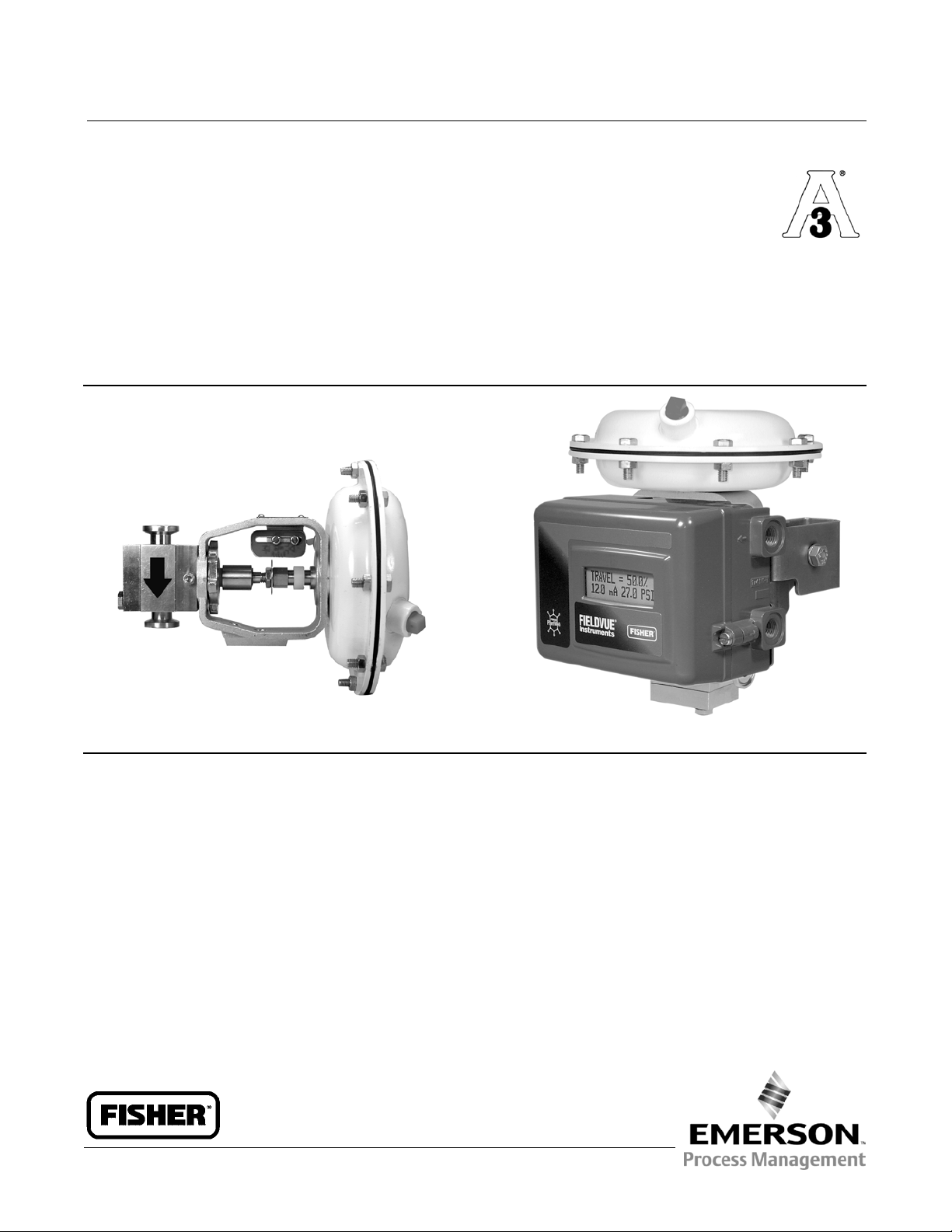
Figure 1. Baumann 87000 Valve
W9823
RECOMMENDED MOUNTING POSITION
FOR SELF-DRAINING
Air Piping 3...................................
Disassembly of Valve 4.........................
Reassembly of Valve 4.........................
Parts Ordering 5................................
Mode of Operation 7............................
Dimensions and Weights 8.......................
W9824
WITH FIELDVUE™ DVC2000
DIGITAL VALVE CONTROLLER
Introduction
The Baumann 87000 Flexsleev control valve (figure 1) with tri-clamp body connections and polished flow contours, is
excellent for throttling high purity liquid or gaseous media. The valve is suitable for repeated steam sterilization cycles
with 35 psi maximum steam pressures. Assembly of valve bodysectionsusesonlytwoboltsallowingforeaseof
cleaning and inspection. A lower telltale port is provided. The valve will drain either horizontally or vertically with the
actuator in the horizontal position. The operation is not affected by vacuum.
Scope of Manual
This instruction manual includes installation, maintenance, and parts information for the Baumann 87000 sanitary
control valve.
Do not install, operate, or maintain Baumann 87000 control valves without being fully trained and qualified in valve,
actuator, and accessory installation, operation, and maintenance. To avoid personal injury or property damage, it is
www.Fisher.com
Page 2

87000 Valve
November 2011
Instruction Manual
D103373X012
important to carefully read, understand, and follow all the contents of this manual, including all safety cautions and
warnings. If you have any questions about these instructions, contact your Emerson Process Management sales office
before proceeding.
WARNING
Always wear protective gloves, clothing and eyewear when performing any installation operations to avoid personal
injury.
Personal injury or property damage caused by sudden release of pressure or bursting of pressure retaining parts may result
if service conditions exceed those for which the product was intended. To avoid injury or damage, provide a relief valve for
over pressure protection as required by government or accepted industry codes and good engineering practices.
Check with your process or safety engineer for any additional measures that must be taken to protect against process
media.
If installing into an existing application, also refer to the WARNING at the beginning of the Maintenance section in this
instruction manual.
CAUTION
This valve is intended for a specific range of pressures, temperatures and other application specifications. Applying
different pressures and temperatures to the valve could result in parts damage, malfunction of the control valve or loss of
control of the process. Do not expose this product to service conditions or variables other than those for which the product
was intended. If you are not sure what these conditions are you should contact your Emerson Process Management sales
office for more complete specifications. Provide the product serial numbers (shown on the nameplate) and all other
pertinent information.
WARNING
If you move or work on an actuator installed on a valve with loading pressure applied, keep your hands and tools away
from the stem travel path to avoid personal injury. Be especially careful when removing the stem connector to release all
loading on the actuator stem whether it be from air pressure on the diaphragm or compression in the actuator springs.
Likewise take similar care when adjusting or removing any optional travel stop. Refer to the relevant actuator Maintenance
Instructions.
Maintenance
WARNING
Avoid personal injury and property damage from sudden release of process pressure or bursting of parts. Before
performing any maintenance operations:
D Do not remove the actuator from the valve while the valve is still pressurized.
D Always wear protective gloves, clothing, and eyewear when performing any maintenance operations.
D Disconnect any operating lines providing air pressure, electric power, or a control signal to the actuator. Be sure the
actuator cannot suddenly open or close the valve.
2
Page 3

Instruction Manual
D103373X012
D Use bypass valves or completely shut off the process to isolate the valve from process pressure. Relieve process pressure
on both sides of the valve. Drain the process media from both sides of the valve.
D Depending on the actuator construction, it will be necessary to manage the pneumatic actuator spring
pre-compression. It is essential to refer to the relevant actuator instructions in this manual to perform safe removal of
the actuator from the valve.
D Uselock-outprocedurestobesuretheabovemeasures stay in effect while you work on the equipment.
D The valve packing box may contain process fluids that are pressurized, even when the valve has been removed from the
pipeline. Process fluids may spray out under pressure when removing the packing hardware or packing rings, or when
loosening the packing box pipe plug.
D Check with your process or safety engineer for any additional measures that must be taken to protect against process
media.
Note
Whenever a gasket seal is disturbed by removing or shifting gasketed parts, install a new gasket during reassembly. This provides a
good gasket seal because the used gasket may not seal properly.
87000 Valve
November 2011
WARNING
Avoid personal injury or property damage by thoroughly cleaning the line of all dirt, welding chips, scale, oil or grease, and
other foreign material. Failure to do so could result in damage to the seating and sealing surfaces of the valve and result in
release of process materials.
Installation and Maintenance
1. Before installing the valve in the pipeline, thoroughly clean the line of all dirt, welding chips, scale, oil or grease, and
other foreign material. A micron size filter is recommended upstream of the valve.
2. Install the valve so the controlled fluid will flow through the valve body in the direction indicated by the arrow on
the valve body.
3. Athree-valvebypassmustbeusedtopermitremovalofthecontrolvalvefromthelinewithoutshuttingdownthe
system.
WARNING
To avoid personal injury or property damage, do not attempt to do any work on a valve while the system is in operation,
the valve must be isolated 100% from the active system and the isolated line voided of pressure and/or hazardous fluids.
Air Piping
Refer to figure 2.
1. For an air-to-extend actuator (air-to-close action), connect the actuating air pressure line to the 1/4 NPT opening in
the upper diaphragm case. For an air-to-retract actuator (air-to-open action) connect the actuating air pressure line
to the 1/4 NPT in the lower diaphragm case.
3
Page 4

87000 Valve
November 2011
2. Use 6.4 mm (1/4 inch) O.D. tubing or equivalent for all air lines. If the air line exceeds 8 m (25 ft) in length, 9.5 mm
(3/8 inch) tubing is preferred. For proper operation, air lines must not leak. Air pressure should not exceed 2.5 bar
(35 psig).
3. Tri-clamp connections should line up properly to provide a tight seal.
Instruction Manual
D103373X012
CAUTION
Do not place the valve in a vise. This will damage the exterior of the valve body and possibly the end connections of the
valve.
WARNING
If there is evidence of process fluid under pressure leaking from the joint, retighten the valve body/joint nuts. Return to the
Warning at the beginning of the Installation and Maintenance section to ensure proper steps have been taken to isolate the
valve and relieve process pressure.
Disassembly of Valve
Refer to figure 3.
1. Depressurize the pipeline and valve interior. Disconnect air lines from the positioner.
2. Loosen the tri-clamp connections and remove the valve from the line.
3. Remove the hex head cap screws (key 12) that secure the valve body to the lower bonnet (key 3) and the upper
bonnet (key 2). Remove the upper bonnet, actuator and positioner from the valve. Be sure the ceramic ball (key 5)
does not fall out of the assembly and get lost.
4. In order to remove the shaft (key 4), unscrew the alignment pin (key 15) and remove the retaining ring (key 11).
Reassembly of Valve
Refer to figures 3, 4, and 5.
1. Reassemble the valve in reverse order using the instructions above. The valve body is designed so it cannot be
assembled improperly. Make sure the beveled edge of the anvil (key 8) points toward the ceramic ball (key 5). Make
sure the tapered end of the sleeve bushing (key 6) also points towards the ceramic ball.
2. If the sleeve (key 7) seating surface is distorted, the sleeve should be replaced, or be rotated to use a new seating
surface.
3. New O-rings (keys 9 and 50) should be installed after suitable lubrication (e.g. food grade) of the shaft O-ring (key
50).
4. Make sure the alignment pin (key 15) is tight and the shaft (key 4) moves easily.
5. Refer to separate instructions for the actuator (D103352X012) and positioner assembly and maintenance.
6. Place the actuator yoke over the shaft (key 4). While tilting the actuator back, drop the yoke drive nut (key 16) over
the shaft (key 4). Run the locknut (key 27), and travel indicator (key 58) down as far as possible onto the shaft (key
4).
7. Carefully place the actuator yoke in a vertical position and thread the actuator stem onto the shaft, spin the
actuator onto the shaft as far as it will go before adjusting the bench range. Refer to Baumann Pneumatic Actuators
instruction manual, D103352X012.
4
Page 5

Instruction Manual
D103373X012
87000 Valve
November 2011
Parts Ordering
When corresponding with your Emerson Process Management sales office about this equipment, always mention the
valve serial number. When ordering replacement parts, also specify the key number, part name, and desired material
using the following parts tables.
WARNING
Use only genuine Fisherr replacement parts. Components that are not supplied by Emerson Process Management should
not, under any circumstances, be used in any Fisher valve, because they may void your warranty, might adversely affect the
performance of the valve, and could cause personal injury and property damage.
Figure 2. Baumann 87000 Valve
E1369
AIR-TO-EXTEND (AIR-TO-CLOSE ACTION) AIR-TO-RETRACT (AIR-TO-OPEN ACTION)
E1234
Figure 3. Baumann 87000 Flexsleev Valve Assembly
E1295
5
Page 6

87000 Valve
November 2011
Instruction Manual
D103373X012
Figure 4. Upper Bonnet and Sleeve Bushing
UPPER BONNET
(KEY 2)
SLEEVE BUSHING
(KEY 6)
TAPERED END OF
SLEEVE BUSHING
W9920
HOLE FOR
ALIGNMENT
PIN (KEY 15)
Figure 5. Upper Bonnet and Sleeve Bushing
BEVELED EDGE
W9921
Table 1. Baumann 87000 Parts List
KEY
QTY DESCRIPTION
NO.
1 1
2 1 Bonnet, Upper 87305
3 1 Bonnet, Lower 87306
4 1 Shaft 87505
5 1 Ceramic Ball 87405
6* 1 Sleeve Bushing 87605
7* 1
8 1 Anvil 87406
9* 2
10* 1 Spring, Stem 87803
11 1 Retaining Ring 87806
12 2 Hex Head Cap Screw 87807
13 1 Spring, Seat 87802
14 1 Protecting Cap 87801
15 1 Alignment Pin 87805
16 1 Drive Nut, Actuator Yoke 011757-003-153
27 1 Jam Nut (locknut) 81841
50* 1 O-Ring 24080
58 1 Travel Indicator 011765-002-152
Valve Body, Cv= 0.25 (orifice diameter = 3.18 mm [0.125 inches]) 87104 87104-1
Valve Body, Cv = 1.25 (orifice diameter = 9.40 mm [0.370 inches]) 87105 87105-1
Sleeve, VMQ (Silicone) 87705-688
Sleeve, EPDM 87705-709
Sleeve, FKM (Fluorocarbon) 87705-697
Sleeve, FFKM (Perfluoroelastomer)(Consult Factory) 87705-703
O-Ring, VMQ (Silicone) 87706-688
O-Ring, EPDM 87706-709
O-Ring, FKM (Fluorocarbon) 87706-697
O-Ring, FFKM (Perfluoroelastomer)(Consult Factory) 87706-703
30 Ra 20 Ra
PART NUMBER
6
Page 7

Instruction Manual
D103373X012
Figure 6. Mode of Operation
FLOW
87000 Valve
November 2011
SHOWN 90DEGREES
OUT OF POSITION FOR
CLARITY
E1296
OPEN
CLOSED
Mode of Operation
As shown in figure 6, a flexible sleeve is inserted through the length of the valve and sealed between the valve body
and bonnet by O-rings. The actuator-motivated valve stem has a tapered groove that pushes a ceramic ball against the
inside of the sleeve and, thereby, the sleeve against a valve seat.
Figure 7. Sleeve Clearance
E1374
7
Page 8

87000 Valve
November 2011
Figure 8. Dimensions
Instruction Manual
D103373X012
FLOW
38
(1.5)
21
(0.83)
21
(0.83)
70
(2.75)
FLOW
9
(0.34)
SELF-DRAIN
ANGLE
2 DEGREES
26
(1.03)
146
(5.8)
159
(46.25)
27
(1.05)
E1297
9
(0.34)
RECOMMENDED MOUNTING FOR SELF-DRAINING (ACTUATOR SHOULD BE MOUNTED HORIZONTALLY)
NOTE: ACTUATOR REQUIRES 115 mm(4.5 INCHES) VERTICAL CLEARANCE.
mm
(inch)
8
Page 9

Instruction Manual
D103373X012
Figure 9. Dimensions
166
(6.52)
87000 Valve
November 2011
E1299
127 (5.0)
RECOMMENDED MOUNTING FOR SELF-DRAINING (ACTUATOR SHOULD BE MOUNTED HORIZONTALLY)
NOTE: ACTUATOR REQUIRES 115 mm(4.5 INCHES) VERTICAL CLEARANCE.
mm
(inch)
9
Page 10

87000 Valve
November 2011
Figure 10. Dimensions
Instruction Manual
D103373X012
205
(48.06)
E1298
6
(40.25)
26
(1.03)
146
(5.8)
159
(46.25)
211
(8.3)
250
(9.8)
RECOMMENDED MOUNTING FOR SELF-DRAINING (ACTUATOR SHOULD BE MOUNTED HORIZONTALLY)
NOTE: ACTUATOR REQUIRES115mm (4.5 INCHES) VERTICAL CLEARANCE.
R228
(R9.0)
mm
(inch)
Table 2. Weights, Valve, Actuator, and Positioner
VALVE ACTUATOR POSITIONER
Size Travel Weight Baumann 16 FIELDVUE DVC2000 FIELDVUE DVC6010
DN NPS mm Inch kg lb kg lb kg lb kg lb
15 1/2 7.9 0.3125 3.6 8 4.5 10 1.5 3.3 3.5 7.7
1. Not available with Fisher 3660/3661 positioner.
(1)
10
Page 11

Instruction Manual
D103373X012
87000 Valve
November 2011
11
Page 12

87000 Valve
November 2011
Instruction Manual
D103373X012
Neither Emerson, Emerson Process Management, nor any of their affiliated entities assumes responsibility for the selection, use or maintenance
of any product. Responsibility for proper selection, use, and maintenance of any product remains solely with the purchaser and end user.
Baumann, Fisher, and FIELDVUE are marks owned by one ofthe companies in the Emerson Process Management business division of Emerson ElectricCo.
Emerson Process Management, Emerson, and the Emerson logo are trademarks and service marks of Emerson Electric Co. All other marks are the property
of their respective owners.
The contents of this publication are presented for informational purposes only, and while every effort has been made to ensure their accuracy, they arenot
to be construed as warranties or guarantees, express or implied, regarding the products or services described herein or their use or applicability. All sales are
governed by our terms and conditions, which are availableupon request.We reserve theright to modify or improve the designs or specifications of such
products at any time without notice.
Emerson ProcessManagement
Marshalltown, Iowa 50158 USA
Sorocaba, 18087 Brazil
Chatham, KentME4 4QZ UK
Dubai, United Arab Emirates
Singapore 128461 Singapore
www.Fisher.com
12
EFisher Controls International LLC 2009, 2011; All Rights Reserved
 Loading...