

Page 1
Instruction Manual
D103363X012
Baumann™ 26000 Corrosion Resistant
Control Valve
26000 Valve
May 2012
Contents
Introduction 1...................................
Scope of Manual 1.............................
Safety Precautions 2...........................
Maintenance 2.................................
Installation 3..................................
Air Piping 4...................................
Packing Adjustments 4.........................
Disassembly 4................................
Reassembly and Calibration 4...................
Parts Ordering 6................................
Dimensions and Weights 9.......................
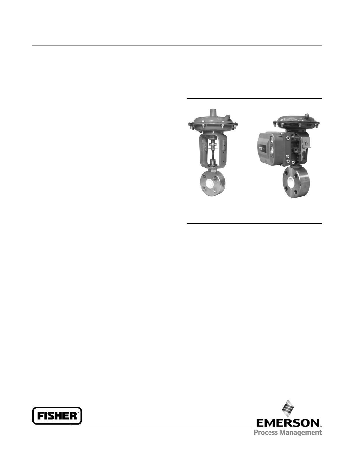
Figure 1. Baumann 26000 Control Valve
W9766
26000 Control Valve with
Baumann 32 Actuator
andDualTravelStops
X0423-1
26000 Valve with Baumann 32
Actuator, Dual Travel Stops, and
FIELDVUEt DVC6200 Digital
Valve Controller
Introduction
The Baumann 26000 Corrosion Resistant Control Valve (figure 1) features a flangeless wafer valve body. The 316
stainless steel flangeless body and thru-hole wafer design allows for installation between plastic pipeline flanges
without risk of gasket leakage. This same valve body, fully pressurized, retains an all wetted PTFE interior resulting in a
solid mechanical structure.
Scope of Manual
This instruction manual includes installation, maintenance, and parts information for the Baumann 26000 corrosion
resistant control valve.
Do not install, operate, or maintain Baumann 26000 control valves without being fully trained and qualified in valve,
actuator, and accessory installation, operation, and maintenance. To avoid personal injury or property damage, it is
important to carefully read, understand, and follow all the contents of this manual, including all safety cautions and
warnings. If you have any questions about these instructions, contact your Emerson Process Management sales office
before proceeding.
www.Fisher.com
Page 2

26000 Valve
May 2012
Instruction Manual
D103363X012
WARNING
Always wear protective gloves, clothing and eyewear when performing any installation operations to avoid personal
injury.
Personal injury or property damage caused by sudden release of pressure or bursting of pressure retaining parts may result
if service conditions exceed those for which the product was intended. To avoid injury or damage, provide a relief valve for
over pressure protection as required by government or accepted industry codes and good engineering practices.
Check with your process or safety engineer for any additional measures that must be taken to protect against process
media.
If installing into an existing application, also refer to the WARNING at the beginning of the Maintenance section in this
instruction manual.
CAUTION
This valve is intended for a specific range of pressures, temperatures and other application specifications. Applying
different pressures and temperatures to the valve could result in parts damage, malfunction of the control valve or loss of
control of the process. Do not expose this product to service conditions or variables other than those for which the product
was intended. If you are not sure what these conditions are you should contact your Emerson Process Management sales
office for more complete specifications. Provide the product serial numbers (shown on the nameplate) and all other
pertinent information.
WARNING
If you move or work on an actuator installed on a valve with loading pressure applied, keep your hands and tools away
from the stem travel path to avoid personal injury. Be especially careful when removing the stem connector to release all
loading on the actuator stem whether it be from air pressure on the diaphragm or compression in the actuator springs.
Likewise take similar care when adjusting or removing any optional travel stop. Refer to the relevant actuator Maintenance
Instructions.
If hoisting the valve, take care to prevent people from being injured in case the hoist or rigging slips. Be sure to use
adequate sized hoists and chains or slings to handle the valve.
WARNING
Personal injury could result from packing leakage. Valve packing is tightened before shipment; however, the packing
might require some readjustment to meet specific service conditions.
Maintenance
WARNING
Avoid personal injury and property damage from sudden release of process pressure or bursting of parts. Before
performing any maintenance operations:
2
Page 3

Instruction Manual
D103363X012
D Do not remove the actuator from the valve while the valve is still pressurized.
D Always wear protective gloves, clothing, and eyewear when performing any maintenance operations.
D Disconnect any operating lines providing air pressure, electric power, or a control signal to the actuator. Be sure the
actuator cannot suddenly open or close the valve.
D Use bypass valves or completely shut off the process to isolate the valve from process pressure. Relieve process pressure
on both sides of the valve. Drain the process media from both sides of the valve.
D Depending on the actuator construction, it will be necessary to manage the pneumatic actuator spring
pre-compression. It is essential to refer to the relevant actuator instructions in this manual to perform safe removal of
the actuator from the valve.
D Use lock-out procedures to be sure the above measures stay in effect while you work on the equipment.
D The valve packing box may contain process fluids that are pressurized, even when the valve has been removed from the
pipeline. Process fluids may spray out under pressure when removing the packing hardware or packing rings, or when
loosening the packing box pipe plug.
D Check with your process or safety engineer for any additional measures that must be taken to protect against process
media.
Note
Whenever a gasket seal is disturbed by removing or shifting gasketed parts, install a new gasket during reassembly. This provides a
good gasket seal because the used gasket may not seal properly.
26000 Valve
May 2012
WARNING
Avoid personal injury or property damage by thoroughly cleaning the line of all dirt, welding chips, scale, oil or grease, and
other foreign material. Failure to do so could result in parts damage, malfunction of the control valve or loss of control of
the process.
To avoid personal injury or property damage, do not attempt to do any work on a valve while the system is in operation,
the valve must be isolated 100% from the active system and the isolated line voided of pressure and/or hazardous fluids.
Installation
1. Before installing the valve in the pipeline, thoroughly clean the line of all dirt, welding chips, scale, oil or grease, and
other foreign material.
2. Install the valve so the controlled fluid will flow through the valve body in the direction indicated by the arrow cast
on the valve body.
3. Athree-valvebypassmustbeusedtopermitremovalofthecontrolvalvefromthelinewithoutshuttingdownthe
system.
4. In case of a heat-insulated installation, insulate the valve body only, not the bonnet.
CAUTION
The PTFE valve body insert protrudes slightly beyond both sides of the valve body (key 1); it is highly recommended that
the included PTFE encapsulatedline flange adapter gaskets (key 21) be utilized. (Refer to figures 3, 2, and 4).
3
Page 4

26000 Valve
May 2012
Instruction Manual
D103363X012
Air Piping
1. For an air-to-extend actuator (air-to-close action), connect the actuating air pressure line to the 1/4 NPT opening in
the upper diaphragm case. For an air-to-retract actuator (air-to-open action) connect the actuating air pressure line
to the 1/4 NPT in the lower diaphragm case.
2. Use 6.4 mm (1/4 inch) O.D. tubing or equivalent for all air lines. If air line exceeds 8 m (25 ft) in l ength, 9.5 mm (3/8
inch) tubing is preferred. Air lines must not leak. Air pressure not to exceed 2.5 bar (35 psig).
Packing Adjustments
Refer to figures 3, 2, and 4)
Should seat leakage or leakage by the bonnet (key 8) occur, try to retighten the internal packing (key 17) by
disconnecting the air line to the actuator, loosen the hex clamp nut (key 12) and turn the bonnet (key 8) clockwise into
the valve body (key 1). This rotation will compress the packing (key 17) around the plug and stem assembly (key 4) and
against the valve body interior. Retighten the hex clamp nut (key 12) and recheck for leakage.
Should the valve stem packing (key 14) need to be adjusted, turn the packing follower (key 10) clockwise to tighten or
counterclockwise to loosen.
Disassembly
Significant wear or contamination may require replacement of the plug or seals. Proceed as follows:
1. Loosen the yoke clamp nut (key 9) and disconnect the actuator (see appropriate actuator instructions).
2. Loosen the packing follower (key 10) and the hex clamp nut (key 12).
3. Unscrew and remove the bonnet (key 8) from the valve body (key 1).
4. Remove the packing (key 17) from the valve body (key 1) by flowing air into port A. This will drive the V-ring packing
seals and plug out of the top opening of the valve body.
CAUTION
The PTFE valve body insert protrudes slightly beyond both sides of the valve body (key 1); it is highly recommended that
the included PTFE encapsulatedline flange adapter gaskets (key 21) be utilized.
Reassembly and Calibration
1. Lay out all parts and clean the valve body thoroughly.
2. Hold the valve body (key 1) upside down, see figure 5.
3. Insert the lower (half round) packing ring.
Note
The flat side should rest in the bottom of the housing bore.
4
Page 5

Instruction Manual
D103363X012
26000 Valve
May 2012
4. Insert the first packing V-ring with the V opening facing the lower ring. Tip the ring slightly to prevent the ring from
hanging up at the corner of the outlet port, see figure 5.
5. For Cv < 1.0, insert a spacer ring (key 3) with the V opening towards first packing ring. Note: The cross hole must
line up with the hole B in a radial direction and within 1/16 inch in the vertical direction. The spacer ring (key 3) is
not required in Cv = 2.5 or Cv = 4.2.
6. Insert the remainder of the packing V-rings (key 17) as shown, one at a time. Tip each ring slightly to ease
installation.
7. Move the valve body (key 1) right-side up and clamp in a vise or test fixture, using the line flange adapter gaskets
(key 21).
8. Screw the hex clamp nut (key 12) all the way onto the lower thread of the bonnet (key 8).
9. Screw the bonnet seal (key 50) all the way onto the lower thread of the bonnet (key 8) until it touches the nut (key
12).
10. Lubricate the lower bonnet thread with anti-seize lubricant and insert the valve plug and stem assembly (key 4)
into the bonnet (key 8).
11. Screw the bonnet (key 8) with the plug and stem assembly (key 4) loosely into the valve body (key 1).
12. Push the stem all the way down until the plug is fully seated.
13. Install the valve body in the test fixture or between a pair of appropriate mating line flanges.
14. Apply 50 psi air pressure to the fixture or the flange connected to valve port A and connect port B to a flow meter
or bubble indicator (tube in water).
15. For Cv < 1.0, slowly screw the bonnet (key 8) into the valve body with a 1-1/4 inch wrench until the air flow stops
completely. Push the valve stem up and down several times and repeat the leakage test. For Cv > 1.0, screw the
bonnet (key 8) down until it touches the packingandthenturnanadditional180degrees.
Note
The force to pull up or push down the stem should not exceed 25 lbs.
16. Close off air flow leaving port B and pull up the stem. This will pressurize all parts of the valve body.
17. Apply leak detection fluid or soap solution to the thread between the valve body and bonnet (key 8). There should
be no leakage.
18. Hold the bonnet in place and tighten the nut (key 12) firmly (this will compress the bonnet seal (key 50).
19. Install the secondary packing kit [packing spring (key 6), washer (key 16), stem packing rings (key 14), packing
spacer (key 20) and packing follower (key 10)] into the bonnet as shown in figure 6. Tighten by rotating the packing
follower (key 10) nut clockwise.
20. Attach the actuator to the bonnet. Turn the actuator to thread the actuator stem onto the valve stem until the
yoke touches the shoulder of the bonnet.
21. Lock the drive nut (key 9), see figures 3, 2, and 4.
22. Apply 4 to 5 psi to the actuator for air-to-open or 13 to 14 psi for air-to-close.
23. With 50 psi air applied to port A, counter tighten the jam nuts (key 27) and slowly turn the valve plug and stem
assembly (key 4) clockwise to thread it into the actuator stem. Stop and lock the stem with the jam nut (key 27)
when port B shows some minimum flow.
24. Adjust the zero position of the travel indicator to the present position of the travel indicator disk (key 58).
25. Reduce air pressure to 3 psi for air-to-open or increase air pressure to 15 psi for air-to-close. For Cv < 1.0, there
should be no seat leakage (Class VI). For Cv > 1.0, the allowed leakage is Class IV. If leakage is noted, loosen the jam
nuts (key 27) and turn the plug and stem assembly (key 4) further into the valve bonnet (key 8).
5
Page 6

26000 Valve
May 2012
Instruction Manual
D103363X012
26. At the lowest actuator travel position, the indicator disk (key 58) shall be at least 0.040 inches below the zero
travel position. If not, move the stem (key 4) further into the bonnet (key 8) and recalibrate the travel indicator.
27. Check the valve travel for a full 1/2 inch from the zero point on the indicator scale.
28. Check the dead band of the actuator. The difference between the signal to move the stem up and the signal to
move stem down shall not exceed 2 psi. If it does exceed 2 psi, the secondary packing (key 14) is too tight.
29. See appropriate actuator instructions to set the travel stops. (Refer to illustrations in the appropriate actuator
instruction manual to determine what type of stops are being used).
30. Attach and calibrate the positioner.
Note
Travel should commence from the zero travel indicator mark at 3.2 psi (4.3 mA) air-to-open or at 14.8 psi (19.7 mA) air-to-close.
The flow should enter only through the lower port A to help energizethe V-ring packing set (key 17).
Parts Ordering
When corresponding with your Emerson Process Management sales office about this equipment, always mention the
valve serial number. When ordering replacement parts, also specify the key number, part name, and desired material
using the following parts tables.
WARNING
Use only genuine Fisherr replacementparts.ComponentsthatarenotsuppliedbyEmersonProcessManagementshould
not, under any circumstances, be used in any Fisher valve, because they may void your warranty, might adversely affect the
performance of the valve, and could cause personal injury and property damage.
6
Page 7

Instruction Manual
D103363X012
Table 1. Parts List
Key No. Description CL150 / PN 10, 16, & 25 CL300
Valve Body with PTFE Insert, Cv= 0.001 - 1.0 26514 26514-3
1
3* Spacer (Cv = .001 - 1.0 ONLY) 26507 26507
4*
8
9 Drive Nut (Yoke) 011757-003-153
10 Packing Follower 24490-1
12 Hex Clamp Nut 26542
14* Secondary Packing Kit, V-Ring, standard 24494T001
17* Primary Packing, Cv < 1.0 (6 rings) 26516
21 Line Flange Adapter Gaskets, qty 2 86814
27 Jam Nut, qty 2 971514-002-250
50 Bonnet Seal 26539
58 Travel Indicator 24299
1. Add letter T orH to the end ofthe part number to indicateTantalum or N10276 nickel alloy plug material.
Valve Body with PTFE Insert, Cv= 2.5 26526 26526-3
Valve Body with PTFE Insert, Cv= 4.2 26532 26532-3
Plug & Stem Subassembly, Cv=0.001 26520-008-999
Plug & Stem Subassembly, Cv=0.005 26520-007-999
Plug & Stem Subassembly, Cv=0.01 26520-006-999
Plug & Stem Subassembly, Cv=0.02 26520-005-999
Plug & Stem Subassembly, Cv=0.05 26520-004-999
Plug & Stem Subassembly, Cv=0.1 26520-003-999
Plug & Stem Subassembly, Cv=0.2 26520-002-999
Plug & Stem Subassembly, Cv=0.4 26520-001-999
Plug & Stem Subassembly, Cv=0.8 26545-001-999
Plug & Stem Subassembly, Cv=1.0 26545-000-999
Plug & Stem Subassembly, Cv=2.5 26527-002-999
Plug & Stem Subassembly, Cv=4.2 26535-002-999
(1)
(1)
(1)
(1)
(1)
(1)
(1)
(1)
(1)
(1)
(1)
(1)
Bonnet 26505
Bonnet, Extension 26528
Primary Packing, Cv = 2.5 (7 rings) 26523
Primary Packing, Cv = 4.2 (9 rings) 26536
26000 Valve
May 2012
*Recommended spare parts
7
Page 8

26000 Valve
May 2012
Instruction Manual
D103363X012
Figure 2. Valve Body for Cv Rating of 2.5
(Class IV Seat Leakage)
E1289
Figure 4. Valve Body for Cv Rating of 4.2
(Class IV Seat Leakage)
E1288
Figure 3. Valve Body for Cv Ratings of 0.001 to 1.0
(Class VI Seat Leakage)
E1287
CAUTION
It is highly recommended that the included PTFE
encapsulated line flange adapter gaskets (key 21) be
utilized.
Figure 5. Baumann 26000 Valve Body Shown Upside
Down for Assembly Procedure
E1368
8
Page 9

Instruction Manual
D103363X012
26000 Valve
May 2012
Figure 6. Secondary Packing: Spring-Loaded PTFE
V-Ring Packing Kit
E1240
Table 2. Secondary Packing Spring-Loaded PTFE
V-Ring Packing Kit, Part Number 24494T001
Key Number Description Material
6 Spring ASTM A313 S30200
14 Packing Set PTFE/carbon-filled PTFE
16 Washer ASTM A240 S31600
20 Spacer
(filled-Polytetrafluoroethylene)
J-2000
Table 3. Baumann 26000 Valve and Actuator
Weights
VALVE WEIGHT ACTUATOR WEIGHT
kg lbs kg lbs
3.3 7.3 4.5 10
9
Page 10

26000 Valve
May 2012
Figure 7. Dimensions NPS 1 26000 Valve with Baumann 32 Actuator and Dual Travel Stops
Instruction Manual
D103363X012
31 (1.24)
229
(9.0)
71 (2.8)
E1290
(48.5)
57
(2.25)
216
216
(48.5)
44
(1.75)
1/4 NPT
ADJUSTABLE OPEN-CLOSED
DUAL TRAVEL STOPS
PROVIDED AS STANDARD
PTFE COVERED LINEFLANGE ADAPTOR GASKETS
PROVIDED WITH VALVE.
(6.35 mm, 0.25 INCH
THICK)
114
(44.5)
CL150
DN 25
PN 10, 16, 25
CL300
40.625
4HOLESON
43.25 B.C.
40.75
4 HOLES ON
43.50 B.C.
mm
(inch)
CAUTION
The PTFE valve body insert protrudes slightly beyond both sides of the valve body (key 1). It is highly recommended that
the included PTFE encapsulatedline flange adapter gaskets (key 21) be utilized.
10
Page 11

Instruction Manual
D103363X012
Figure 8. Dimensions for Baumann 32 Actuator with Options
216
127 (5.0)
(48.5)
141
(5.5)
227
(8.96)
26000 Valve
May 2012
E1291
OPTIONAL FIELDVUE
DVC2000 DIGITAL VALVE
CONTROLLER
USE HANDWHEEL AS
216
(48.5)
TRAVEL STOP
DUAL STOPS FOR AIRTO-CLOSE / FAIL OPEN
ACTUATION
OPTIONAL FISHER 3660/3661
POSITIONER
152 (46.0)
229
(9.0)
TOP-MOUNTED
HANDWHEEL FOR
AIR-TO-OPEN / FAIL
CLOSED ACTUATION
USE HANDWHEEL AS
TRAVEL STOP
94
(3.7)
OPTIONAL FIELDVUE DIGITAL
VALVE CONTROLLER
160 (46.3)
163
(6.4)
TOP-MOUNTED
HANDWHEEL FOR AIR-
TO-CLOSE / FAIL OPEN
ACTUATION
mm
(inch)
11
Page 12

26000 Valve
May 2012
Instruction Manual
D103363X012
Neither Emerson, Emerson Process Management, nor any of their affiliated entities assumes responsibility for the selection, use or maintenance
of any product. Responsibility for proper selection, use, and maintenance of any product remains solely with the purchaser and end user.
Baumann, Fisher, and FIELDVUE are marks owned by one of the companies in the Emerson Process Management business unit of Emerson Electric Co.
Emerson Process Management, Emerson, and the Emerson logo are trademarks and service marks of Emerson Electric Co. All other marks are the property
of theirrespective owners.
The contents of this publication are presented for informational purposes only, and while every effort has been made to ensure their accuracy, they arenot
to be construed as warranties or guarantees, express or implied, regarding the products or services described herein or their use or applicability. All sales are
governed by our termsand conditions,which are available upon request. We reserve the right to modifyor improve the designs or specifications of such
products at any time without notice.
Emerson Process Management
Marshalltown, Iowa 50158 USA
Sorocaba, 18087 Brazil
Chatham, Kent ME4 4QZ UK
Dubai, United Arab Emirates
Singapore 128461 Singapore
www.Fisher.com
12
E 2009, 2012 Fisher Controls International L LC. All rights reserved.
 Loading...