

Page 1
Product Bulletin
646 Transducer
D101374X012
February 2015
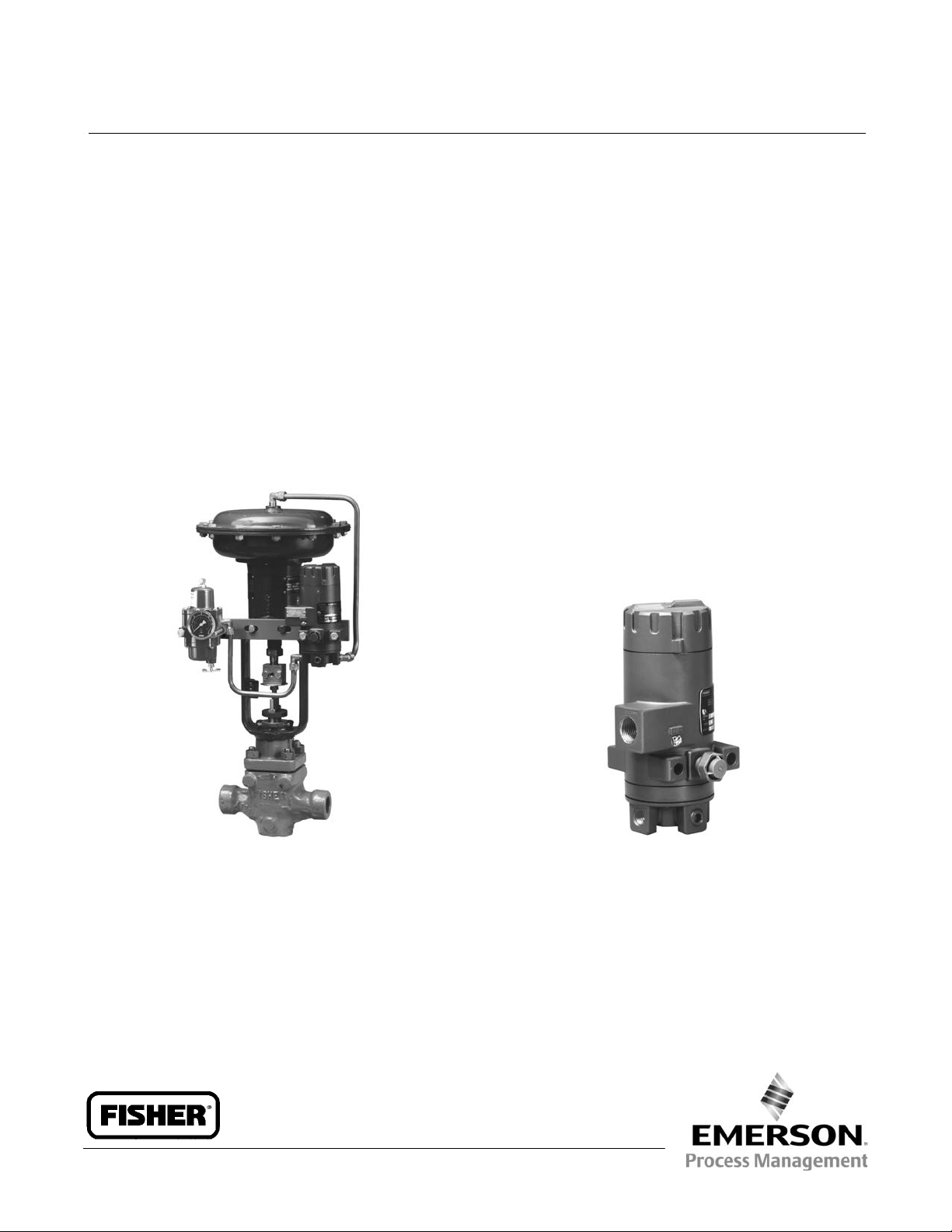
Fisherr 646 Electro-Pneumatic Transducer
62.1:646
The Fisher 646 electro-pneumatic transducer uses a
converter module that converts a 4 to 20 milliampere
input signal to a proportional 0.2 to 1.0 bar (3 to
15 psig) pneumatic output signal. The converter
module uses small parts of minimum mass, which are
balanced symmetrically around a pivot point at the
center of the mass. This balanced arrangement results
in a high performance instrument that reduces
sensitivity to vibration.
An integral pneumatic relay provides the high capacity
necessary to drive pneumatic control valve/acutator
assemblies without additional boosters or positioners.
The transducer also provides stable, accurate
operation when its output is transmitted to small
volume chambers, such as a pneumatic positioner or
other pneumatic instrument. Reduced sensitivity to
vibration combined with high capacity and first order
lag characteristics make the 646 transducer ideal for
direct mounting on control valve/actuator
combinations.
Connectors and piping can be installed with each 646
transducer for diagnostic testing.
FISHER 646 ELECTRO-PNEUMATIC TRANSDUCER
WITH FISHER 657 ACTUATOR AND E VALVE
www.Fisher.com
W6783-1
W4908-1
FISHER 646 ELECTRO-PNEUMATIC TRANSDUCER
Page 2

Product Bulletin
62.1:646
February 2015
Specifications
646 Transducer
D101374X012
Input Signal
4 to 20 mA DC, constant current with 30 VDC
maximum compliance voltage
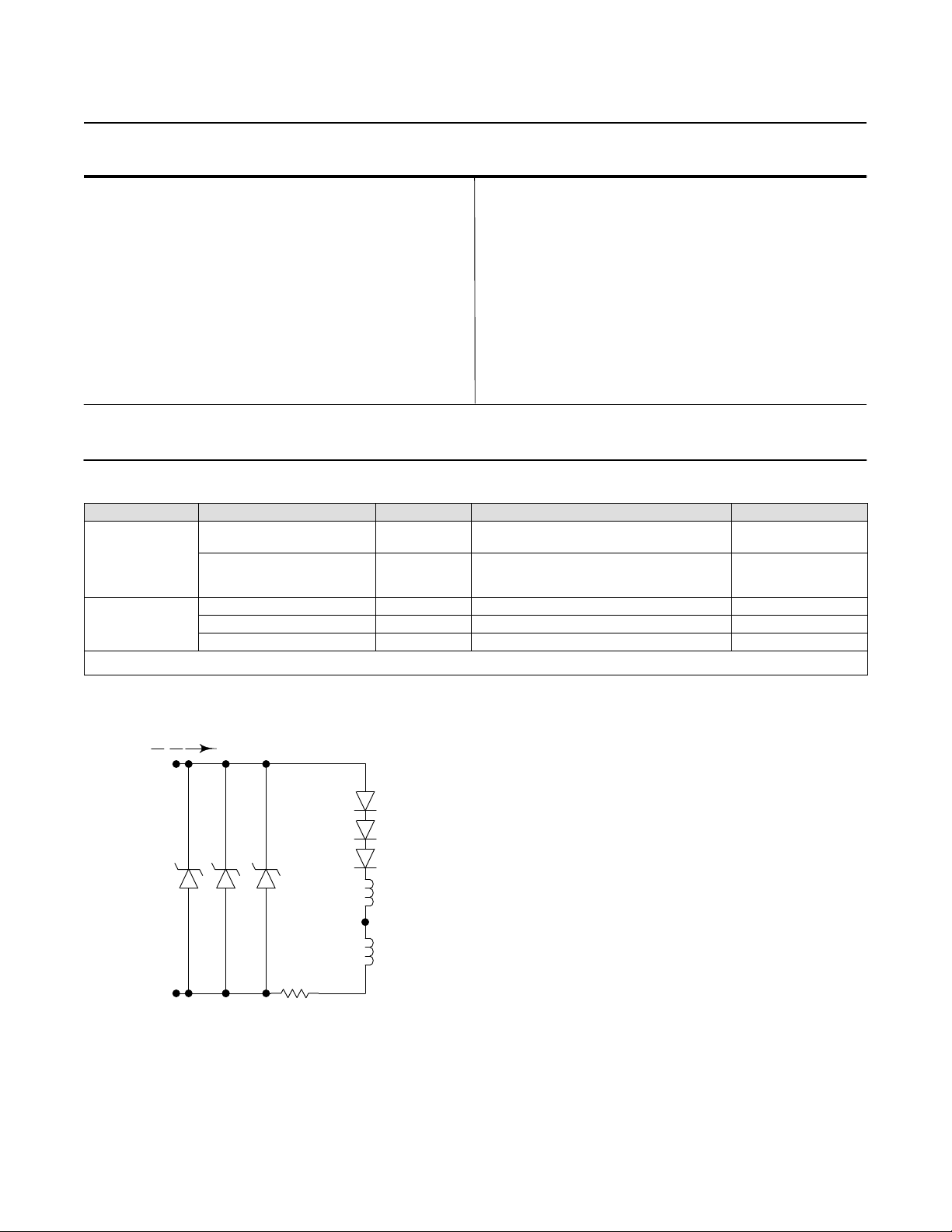
Equivalent Circuit
The 646 equivalent circuit is a series circuit consisting
of a constant voltage drop (battery) of approximately
2.1 VDC and a total resistance of 143 ohms. Input is
shunted by three 6.8 V zener diodes (see figure 1).
Output Signal
0.2 to 1.0 bar (3 to 15 psig) direct acting only
Supply Pressure
(1)
Recommended: 1.4 bar (20 psig)
Minimum: 1.4 bar (20 psig)
Maximum: 3.4 bar (50 psig)
Average Steady‐State Air Consumption
(2)(3)
0.08 m3/hr (3 scfh) at 1.4 bar (20 psi) supply pressure
Maximum Output Air Capacity
(2)
8.0 m3/hr (300 scfh) at 1.4 bar (20 psig) supply
pressure
Performance
(4)
Reference Accuracy: ±0.5% of full scale output span;
includes combined effects of hysteresis, linearity, and
deadband
Independent Linearity: ±0.5% of full scale output span
Hysteresis: 0.4% of full scale output span
Frequency Response: Gain is attenuated 3 dB at 10 Hz
with transducer output signal piped to a typical
instrument input
Temperature Effect: ±4% of full scale output span per
55_C (100_F) change
Supply Pressure Effect: 0.2% of full scale output span
per psi supply pressure change
Vibration Effect: Less than 1% of full scale output span
when tested to SAMA PMC 31.1, Condition 3
-continued-
Electromagnetic Compatibility:
Meets EN 61326-1 (First Edition)
Immunity—Industrial locations per Table 2 of
the EN 61326-1 standard. Performance is
shown in table 1 below.
Emissions—Class A
ISM equipment rating: Group 1, Class A
Operating Ambient Temperature Limits
(1)
-40 to 71_C (-40 to +160_F)
Electrical Classification
CSA— Intrinsically Safe, Explosion-proof, Type n,
Dust-Ignition proof, Div 2
FM— Intrinsically Safe, Explosion-proof, Type n,
Non-incendive, Dust-Ignition proof
ATEX— Intrinsically Safe, Flameproof, Type n
IECEx— Intrinsically Safe, Flameproof, Type n
Refer to tables 2, 3, 4, and 5 additional information.
Housing
CSA— Type 3 Encl.
FM— NEMA 3, IP54
ATEX— IP64
IECEx— IP54
Mount instrument with vent on side or bottom if
weatherproofing is a concern
Other Classifications/Certifications
CUTR— Customs Union Technical Regulations (Russia,
Kazakhstan, and Belarus)
INMETRO— National Institute of Metrology, Quality
and Technology (Brazil)
KGS— Korea Gas Safety Corporation (South Korea)
Contact your Emerson Process Management sales
office for classification/certification specific
information
Construction Materials
Housing, Cap, and Relay Body: Die cast aluminum
with less than 1% copper
2
Page 3
646 Transducer
D101374X012
Specifications (continued)
Product Bulletin
62.1:646
February 2015
Adjustments
Zero and Span: Trim potentiometers (20 turn) for
zero and span adjustments are located under the
housing cap
Mounting Position
Any position is acceptable for standard pipestand,
panel, or actuator mounting. For weatherproof
housing, mount the transducer to allow the vent to
drain.
Connections
Supply and Output Pressure: 1/4 NPT internal
connection
Vent: 1/4 NPT internal
Electrical:
J Standard 1/2 NPT or, J Optional M20 or
PG13 conduit adapter (see figure 3)
Wire Size: 18 to 22 AWG
NOTE: Specialized instrument terms are defined in ANSI/ISA Standard 51.1 - Process Instrument Terminology.
1. The pressure and temperature limits in this document and any applicable standard or code limitation should not be exceeded.
2. Normal m
3. Average flow rate determined at 12 mA and 0.6 bar (9 psig) output.
4. Performance values are obtained using a transducer with a 4 to 20 mA dc input signal and a 0.2 to 1.0 bar (3 to 15 psig) output signal at an ambient temperature of 24_C (75_F).
3
/hour--Normal cubic meters per hour (0_C and 1.01325 bar, absolute). Scfh--Standard cubic feet per hour (60_F and 14.7 psig).
Approximate Weight (Transducer Only)
1.6 kg (3.5 pounds)
Options
Output pressure gauge
Table 1. EMC Summary Results—Immunity
Port Phenomenon Basic Standard Test Level Performance Criteria
Electrostatic discharge (ESD) IEC 61000-4-2
Enclosure
I/O signal/control
Specification Limit = +/- 1% of span.
1. A = No degradation during testing. B = Temporary degradation during testing, but is self-recovering.
Radiated EM field IEC 61000-4-3
Burst (fast transients) IEC 61000-4-4 1 kV A
Surge IEC 61000-4-5 1 kV (line to ground only, each) B
Conducted RF IEC 61000-4-6 150 kHz to 80 MHz at 3 Vrms A
4 kV contact
8 kV air
80 to 1000 MHz @ 10V/m with 1 kHz AM at 80%
1400 to 2000 MHz @ 3V/m with 1 kHz AM at 80%
2000 to 2700 MHz @ 1V/m with 1 kHz AM at 80%
(1)
A
A
Figure 1. Equivalent Circuit
4 - 20 mA
+
6.8V 6.8V 6.8V
-
A6013
0.7V
0.7V
0.7V
60 Ohms
60 Ohms
23 Ohms
3
Page 4

Product Bulletin
62.1:646
February 2015
646 Transducer
D101374X012
Features
n Small Size—The small size and light-weight design of
the transducer facilitate mounting and provide
improved space utilization.
n Vibration Resistance—The transducer, used in a
standard valve/actuator mounted application,
exhibits an output shift of less than 1 percent of
span when tested to SAMA Standard PMC 31.1,
Condition 3.
n High Output Capability—The output volume of the
transducer is adequate to drive valve/actuator
combinations without requiring a positioner or
volume booster.
n Low Air Consumption—The transducer has low air
consumption which cuts operating costs.
n Easy Maintenance—Modular design of the converter
allows easy replacement in the field for reduced
maintenance costs.
n Superior Performance—The accuracy, linearity, and
frequency response coupled with minimal
hysteresis far exceed the requirements of most
control systems.
Figure 2. Output-Time Relationships
100
90
80
70
60
50
OUTPUT
40
30
(% OF 646 OUTPUT SPAN)
20
10
0
0 1020 3040 506070 8090100
A6815
LOADING
EXHAUSTING
TIME (%)
Installation
Refer to figure 3 for location of standard mounting
holes in the housing. Standard mounting hardware is
provided for mounting on the actuator, a pipestand, or
a panel. Field wiring connections are made to the
terminal block accessible under the housing cap.
Dimensions are shown in figure 3.
Valve Stroking Time
Figure 2 shows relative times for loading and
exhausting an actuator. Stroking time depends upon
the size of the actuator, travel, relay characteristics
and the magnitude and rate of change of the input
signal. If stroking time is critical, contact your Emerson
Process Management sales office.
4
Ordering Information
To determine what ordering information is required,
refer to the specification table. Carefully review the
description of each specification. Specify the desired
choice whenever there is a selection available. Also,
specify options that are applicable to the application.
Page 5

646 Transducer
D101374X012
Product Bulletin
62.1:646
February 2015
Figure 3. Dimensions
FISHER 67CFR
1/4-18 NPT
SUPPLY CONN
6.4
(0.25)
106.4
(4.19)
127.0
(5.00)
102.1
(4.02)
72.8
(2.86)
1/2-14 NPT
OR OPTIONAL
M20 CONDUIT CONN
OPTIONAL
GAUGE
152.4
(6.00)
79.2
(3.12)
(1.88)
47.8
CENTERLINE
OF ACTUATOR
9.7
(0.38)
EXHAUST
152.4
(6.00)
(2.25)
35
(1.38)
1/4-18 NPT
OUTPUT CONN
1/4-18 NPT
OPTIONAL OUTPUT
OR GAUGE CONN
57
CAP
REMOVAL
CLEARANCE
41.1
(1.62)
127.0
(5.00)
62.0
(2.44)
9.5
(0.38)
mm
(INCH)
38B3958-A
A6816-1
5
Page 6

Product Bulletin
62.1:646
February 2015
Table 2. Hazardous Area Classifications—CSA (Canada)
Certification Body Certification Obtained Entity Rating Temperature Code
CSA
Intrinsically Safe
Ex ia IIC T4/T5 per drawing GE28591
Ex ia Intrinsically Safe
Class I, II, Division 1 GP A,B,C,D,E,F,G T4/T5
per drawing GE28591
Explosion-proof
Ex d IIC T6
Class I, Division I, GP A,B,C,D T6
Type n
Ex nL IIC T6
Class I, Division 2, GP A,B,C,D T6
Class II, Division 1, Groups E,F,G T6
Class II, Division 2, GP F,G T6
Vmax = 30 VDC
Imax = 150 mA
Pi = 1.0 W
Ci = 0 nF
Li = 0 mH
- - - T6 (Tamb ≤ 71°C)
- - -
- - - T6 (Tamb ≤ 71°C)
Table 3. Hazardous Area Classifications—FM (United States)
Certification Body Certification Obtained Entity Rating Temperature Code
Vmax = 30 VDC
Imax = 150 mA
Pi = 1.0 W
Ci = 0 nF
Li = 0 mH
- - - T6 (Tamb ≤ 71°C)
- - - T6 (Tamb ≤ 71°C)
- - - T6 (Tamb ≤ 71°C)
FM
Intrinsically Safe
Class 1 Zone 0 AEx ia IIC T4/T5 per drawing GE28590
Class I, II, III Division 1 GP A,B,C,D,E,F,G T4/T5
per drawing GE28590
Explosion-proof
Class 1 Zone 1 AEx d IIC T6
Class I, Division I, GP A,B,C,D T6
Type n
CL 1 Zone 2 AEx nL IIC T6
Class I, Division 2, GP A,B,C,D T6
Class II, Division 1, Groups E,F,G T6
Class II, Division 2, GP F,G T6
646 Transducer
D101374X012
T4 (Tamb ≤ 71°C)
T5 (Tamb ≤ 40°C)
T6 (Tamb ≤ 71°C)
T4 (Tamb ≤ 71°C)
T5 (Tamb ≤ 40°C)
Table 4. Hazardous Area Classifications—ATEX
Certificate Certification Obtained Entity Rating Temperature Code
II 1 G & D
ATEX
Intrinsically Safe
Gas
Ex ia IIC T4/T5 Ga
Dust
Ex ia IIIC T155°C Da (Tamb
T124°C (Tamb ≤ 40°C)
II 2 G & D
Flameproof
Gas
Ex d IIC T6 Gb
Dust
Ex tb IIIC T74°C Db (T
Type n
Gas
Ex nA IIC T6 Gc
Dust
Ex tc IIIC T74°C Dc (T
amb ≤ 71°C)
II 3 G & D
amb ≤ 71°C)
≤ 71°C)
Ui = 30 VDC
Ii = 150 mA
Pi = 1.0 W
Ci = 0 nF
Li = 0 mH
- - - T6 (Tamb ≤ 71°C)
- - - - - -
- - -
T4 (Tamb ≤ 71°C)
T5 (Tamb ≤ 40°C)
T6 (Tamb ≤ 71°C)
- - -
- - -
6
Page 7

Product Bulletin
646 Transducer
D101374X012
Table 5. Hazardous Area Classifications—IECEx
Certificate Certification Obtained Entity Rating Temperature Code
Ui = 30 VDC
Ii = 150 mA
Pi = 1.0 W
Ci = 0 nF
Li = 0 mH
T4 (Tamb ≤ 71°C)
T5 (Tamb ≤ 40°C)
- - - T6 (Tamb ≤ 71°C)
- - - T6 (Tamb ≤ 71°C)
IECEx
Intrinsically Safe
Gas
Ex ia IIC T4/T5 Ga
Flameproof
Gas
Ex d IIC T6 Gb
Type n
Gas
Ex nA IIC T6 Gc
62.1:646
February 2015
7
Page 8

Product Bulletin
62.1:646
February 2015
646 Transducer
D101374X012
Neither Emerson, Emerson Process Management, nor any of their affiliated entities assumes responsibility for the selection, use or maintenance
of any product. Responsibility for proper selection, use, and maintenance of any product remains solely with the purchaser and end user.
Fisher is a mark owned by one of the companies in the Emerson Process Management business unit of Emerson Electric Co. Emerson Process Management,
Emerson, and the Emerson logo are trademarks and service marks of Emerson Electric Co. All other marks are the property of their respective owners.
The contents of this publication are presented for informational purposes only, and while every effort has been made to ensure their accuracy, they are not
to be construed as warranties or guarantees, express or implied, regarding the products or services described herein or their use or applicability. All sales are
governed by our terms and conditions, which are available upon request. We reserve the right to modify or improve the designs or specifications of such
products at any time without notice.
Emerson Process Management
Marshalltown, Iowa 50158 USA
Sorocaba, 18087 Brazil
Chatham, Kent ME4 4QZ UK
Dubai, United Arab Emirates
Singapore 128461 Singapore
www.Fisher.com
E 1988, 2015 Fisher Controls International LLC. All rights reserved.
8
 Loading...