

Page 1
Product Bulletin
644 and 645 Pump Governors
D100185X012
December 2012
Fisherr 644 and 645 Differential Pressure
Pump Governor Actuators
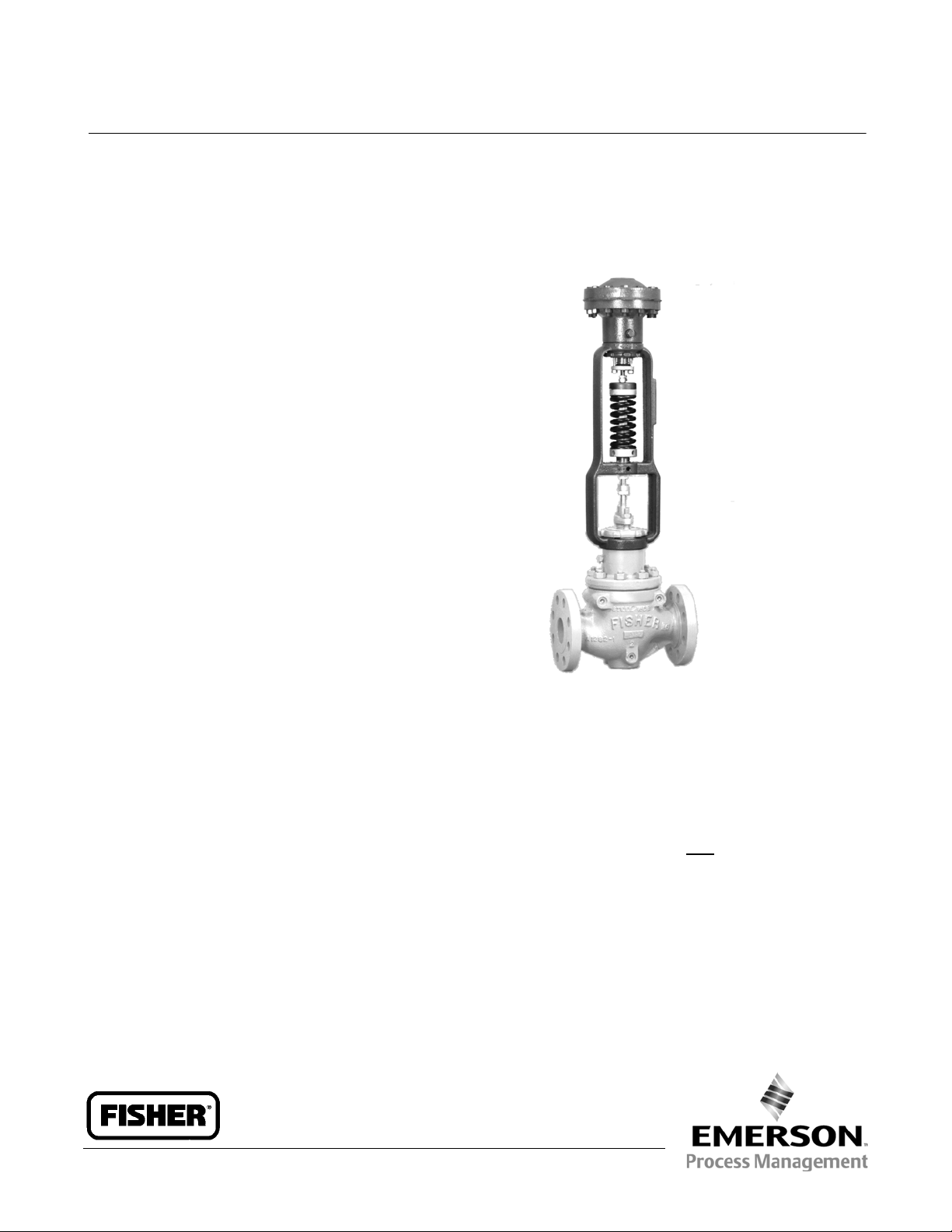
Fisher 644 and 645 actuators are used in combination
with any of several sliding-stem valves to automatically
control steam-driven boiler feedwater pumps
(reciprocating or turbine). The 644 or 645 actuator
(see figure 2), when used in combination with one of
several push-down-to-close sliding-stem valves, forms
a pump governor.
644 and 645 actuators may also be combined with
push-down-to-open valves to be used as relief
governors. Relief governors are used to divert excess
pump discharge back to the suction side of the pump.
61.9:644
Features
Rugged Construction–Steel and cast iron
construction provides long service life.
Ease of Maintenance–Few moving parts and easy
access reduce maintenance and downtime.
Ease of Adjustment–Spring adjustment is readily
accessible without removing any parts.
Fast Acting–Direct-operated configuration provides
fast speed of response.
Determining Buildup or
Droop
To determine the buildup (for relief applications) or
droop (for pressure reducing applications):
1. Find a pressure setting limit range that includes the
required pressure setting from table 1.
W2265-1
Fisher 644 ActuatorMounted on easy-et Valve Body
2. Find the sensitivity factor for the desired spring and
actuator casing combination from table 1.
3. Use the formula below to determine the buildup or
droop required for normal actuator travel.
Y
P=
X
where,
P = Buildup (for pressure relief) or Droop (for pressure
reduction), bar (psig)
Y = Normal actuator travel, mm (inches)
X = Sensitivity factor from table 1 mm/newtons
(inches/psig)
www.Fisher.com
Page 2
Product Bulletin
61.9:644
December 2012
Specifications
644 and 645 Pump Governors
D100185X012
Actuator Sizes
See table 1
Actuator Travel
Chloroprene Diaphragm: 11 mm (0.4375 inch)
maximum
Stainless Steel Diaphragm: 3 mm (0.125 inch)
maximum
Operating Principle
J Direct-acting with push-down-to-close valve
J Reverse-acting with push-down-to-open valve
Differential Pressure Ranges
See table 1
Maximum Casing Pressure
644 Actuator:
Cast-Iron Casing: 20.7 bar (300 psig)
Steel Casing: 41.4 bar (600 psig)
645 Actuator:
Cast-Iron Casing: 34.5 bar (500 psig)
Steel Casing: 69.0 bar (1000 psig)
Maximum nP Across Diaphragm
13.8 bar (200 psi)
Effective Diaphragm Area
644:
Size 1: 146 cm
Size 2: 243 cm
Size 3: 364 cm
645: 338 cm
Material Temperature Capabilities
644:
Chloroprene Diaphragm:-40 to 82_C
(-40 to 180_F)
Stainless Steel Diaphragm:
Cast-iron casing: -40 to 232_C(-40to450_F); Steel
casing: -40 to +399_C(-40to750_F)
645: -37 to 82_C(-35_ to 180_F)
Casing Pressure Connections
1/4 NPT internal
Spring Ranges and Sensitivity
See table 1
2
(8.9 inch2)
2
(14.8 inch2)
2
(22.2 inch2)
2
(20.6 inch2)
Construction Materials
Diaphragm:
644:
J Chloroprene or J Stainless steel
645: Chloroprene
Diaphragm Casing:
Diaphragm Head:
Diaphragm Rod: Stainless Steel
Packing:
J Graphite or J PTFE
J Cast iron or J Steel
J Cast iron or J Steel
Installation
Theseactuatorsmaybeinstalledinanyposition.
Typical installations are shown in figure 1. Dimensions
are shown in figure 3.
Ordering Information
Application
1. Differential pressure
2. Temperature (normal operating and maximum)
Stem Size
644: 9.5mm(3/8inch)
645: 12.7 mm (1/2 inch)
Yoke Boss Diameters
644:
J 54 mm (2-1/8 inch) or
J 71 mm (2-13/16 inch)
645: 71 mm (2-13/16 inch)
3. Required spring
Actuator
Refer to the specifications table. Review the
description to the right of each specification and in the
referenced table. Specify a choice wherever there is a
selection to be made.
Valve Body and Accessories
Refer to separate valve bulletin and bulletins covering
accessories for ordering information.
2
Page 3

644 and 645 Pump Governors
D100185X012
Figure 1. Typical Installation for Pump Governors
CONNECT TO BOILER
PRESSURE
EQUALIZING
VALVE
Product Bulletin
61.9:644
December 2012
BOILER
PRESSURE
STEAM
SUPPLY
14A2729-A
A1762-1
PUMP
GOVERNOR
SUCTION
REGULATING PUMP TO CONTROL
THE DISCHARGE PRESSURE
Table 1. Spring Information
ACTUATOR
644
645
Size 3
Casing
Size 2
Casing
Size 1
Casing
DIFFERENTIAL PRESSURERANGE SPRING RATE SENSITIVITY
Bar Psi N/mm Lbf/in mm/N In/Psi
0.3-1.2
1.2-1.9
1.9-2.8
2.8-3.8
3.8-4.7
4.7-6.9
1.0-1.7
1.7-2.4
2.4-3.2
3.2-4.1
4.1-4.3
4.3-5.9
5.9-6.8
6.8-8.2
8.2-9.7
9.7-10.7
PUMP
DISCHARGE
5-18
18-27
27-40
40-55
55-68
68-100
14-24
24-35
35-47
47-59
59-62
62-85
85-99
99-119
119-140
140-155
14A2789-A
A1763-1
56
107
107
165
107
165
43
64
86
107
129
145
221
257
310
368
PUMP
DISCHARGE
SUCTION
DIVERTING EXCESS DISCHARGE TO
CONTROL THE PRESSURE
314
609
609
940
609
940
246
368
490
612
735
830
1260
1470
1770
2100
26.1
13.5
9.0
6.2
5.4
3.7
21.0
14.0
10.5
11.0
7.1
6.2
4.1
3.5
2.9
2.5
0.0707
0.0365
0.0244
0.0168
0.0146
0.0101
0.057
0.038
0.0286
0.0299
0.0191
0.0169
0.0111
0.0095
0.0079
0.0067
RELIEF
GOVERNOR
SPRING PART NUMBER
1F945527032
1F945627032
1F945627032
1F945727042
1F945627032
1F945727042
1F714427112
1F176727032
1F176827092
1F176927092
1E792327092
1F714327092
1E795327082
1E792427082
1E795427082
1E793327082
3
Page 4

Product Bulletin
(
)
61.9:644
December 2012
644 and 645 Pump Governors
D100185X012
Figure 2. Typical Pump Governor Sectionals
W2263-1
644 ED
W2264-1
645 ED
Table 2. Dimensions
YOKE BOSS
ACTUATOR
644
DIAMETER
mm Inch mm Inch mm Inch mm Inch mm Inch mm Inch mm Inch
54712-1/8
2-13/16
SIZE 1 SIZE 2 SIZE 3 SIZE 1 SIZE 2 SIZE 3
503
19.81
548
21.56
Figure 3. Dimensions
C1/4
AH6723-A
A1742-1
E C(DIAMETER)
521
565
20.50
22.25
522
567
20.56
22.31
644
152 6.00 206 8.12 229 9.00
1/4
NPT
1/4 NPT
E
AH9149-A
A1743-1
264
(10.38)
645
NPT
1/4 NPT
66.4
(26.13)
mm
INCH
Neither Emerson, Emerson Process Management, nor any of their affiliated entities assumes responsibility for the selection, use or maintenance
of any product. Responsibility for properselection, use, and maintenance of any product remains solely with the purchaserand end user.
Fisher andeasy-e are marks owned by one ofthe companies in the Emerson Process Management business unit of Emerson Electric Co. Emerson Process
Management, Emerson, and the Emerson logo are trademarks and service marks of Emerson Electric Co. All other marks are theproperty oftheir respective
owners.
The contents of this publication are presented for informational purposes only, and while every effort has been made to ensure their accuracy, they arenot
to be construed as warranties or guarantees, express or implied, regarding the products or services described herein or their use or applicability. All sales are
governed by our terms and conditions, which are available upon request. We reserve the right to modify or improve the designs or specifications of such
products at any time without notice.
Emerson Process Management
Marshalltown, Iowa 50158 USA
Sorocaba, 18087 Brazil
Chatham, Kent ME4 4QZ UK
Dubai, United Arab Emirates
Singapore 128461 Singapore
www.Fisher.com
E 1997, 2012 Fisher ControlsInternational LLC. All rights reserved.
4
 Loading...