

Page 1
Instructional Manual
D100638X012
December 2018
Types 634 and 634M
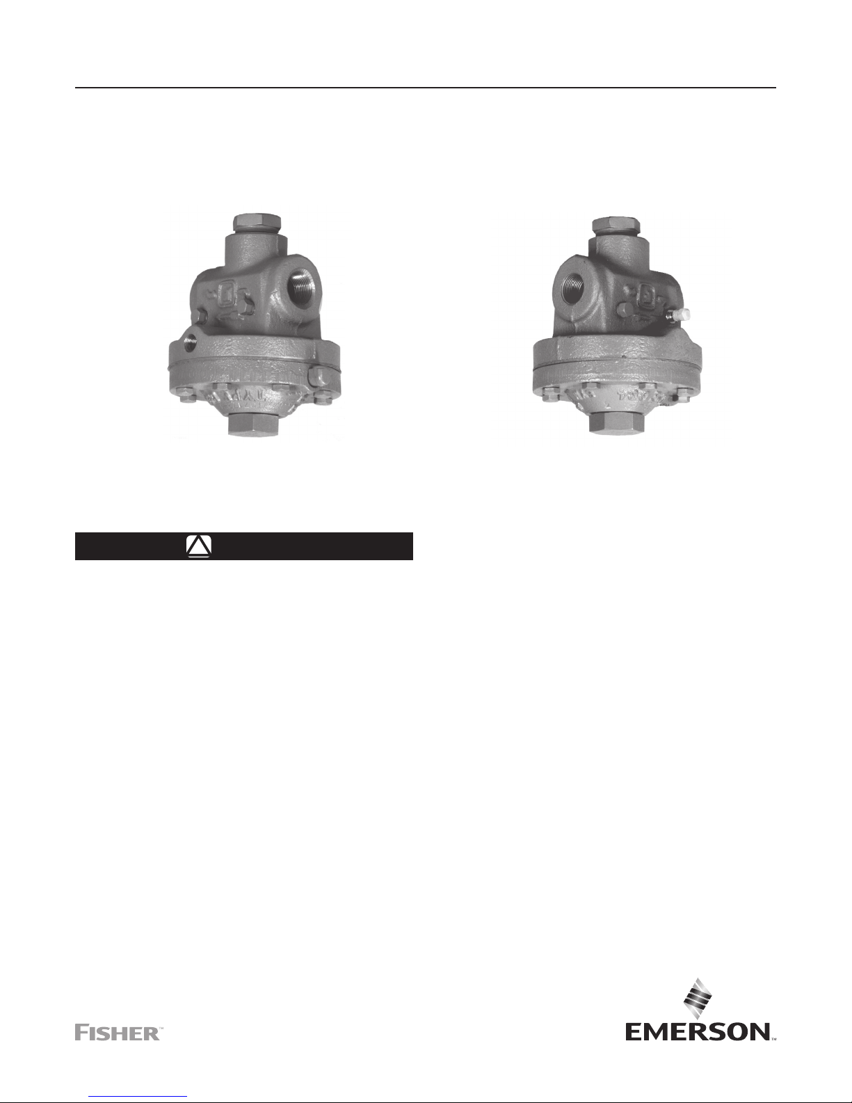
Types 634 and 634M High-Pressure Shutoff Valves
W4128
TYPE 634M SHUTOFF VALVE WITH
STANDARD PIPE PLUGS IN BODY SIDE TAPPINGS
Figure 1. Typical Constructions
WARNING
!
Failure to follow these instructions or
to properly install and maintain this
equipment could result in an explosion,
re and/or chemical contamination
causing property damage and personal
injury or death.
Fisher™ shutoff valve must be installed,
operated and maintained in accordance
with federal, state and local codes, rules
and regulations and Emerson Process
Management Regulator Technologies,
Inc. instructions.
If a leak develops or if the outlet
continually vents gas, service to the
unit may be required. Failure to correct
trouble could result in a hazardous
condition. Only a qualied person shall
install or service the unit.
Call a qualied service person to service
the unit. Installation, operation and
maintenance procedures performed
W4156-1
TYPE 634 SHUTOFF VALVE WITH
OPTIONAL TANK VALVE IN UPSTREAM BODY SIDE TAPPING
by unqualied person may result
in improper adjustment and unsafe
operation. Either condition may result in
equipment damage or personal injury.
Only a qualied person must install
or service the Types 634 and 634M
shutoff valves.
Introduction
Scope of the Manual
This manual provides installation, maintenance, and
parts information for the Types 634 and 634M highpressure shutoff valves. Refer to separate instruction
manuals for information on regulators used with these
high-pressure shutoff valves.
Product Description
Types 634 and 634M high-pressure shutoff valves
(Figure 1) serve to provide overpressure protection by
containment. The Type 634 shutoff valve with internal
registration is installed between a pressure-reducing
Page 2

Types 634 and 634M
Specications
The Specications section on this page provides the ratings and other specications for the Types 634 and 634M.
Factory specications such as type, maximum inlet pressure, maximum temperature, maximum outlet pressure,
spring range and orice size are stamped on the nameplate fastened on the regulator at the factory. The
manufacture date and original fracture disk range are printed on the disk retainer (key 3, Figure 6).
Body Size and End Connection Style
3/4 or 1 NPT internal
Maximum Inlet Pressure
(1)
1500 psig / 103 bar
Maximum Body Outlet Pressure
(1)
Type 634 Shutoff Valve: 150 psig / 10.3 bar
Type 634M Shutoff Valve: 1500 psig / 103 bar
Maximum Diaphragm Pressure
(1)
Operating: 150 psig / 10.3 bar
Emergency
(2)
: 225 psig / 15.5 bar
Outlet Pressure at which Fracture Disk Shatters
See Figure 5
Temperature Capabilities
(3)
-20
to 180°F / -29
Vent Connection
1/4 NPT internal with removable Type Y602-12
vent assembly
Downstream Pressure Registration Connection
(Type 634M Shutoff Valve Only)
1/4 NPT internal
Approximate Weight
13 lbs / 6.0 kg
1. The pressure/temperature limits in this Instruction Manual, and any applicable code or standard limitation should not be exceeded.
2. A pressure exceeding this value can cause failure of, or leakage from, pressure containing components.
3. Low temperatures may stiffen elastomers and prevent normal shutoff.
regulator and a downstream system or equipment
as shown in Figure 2. The Type 634M shutoff valve
with external registration requires a control line and is
installed upstream of a pressure-reducing regulator as
shown in Figure 3.
of accumulated gas. To avoid such
conditions, use qualified personnel
to install a high-pressure shutoff
valve where:
• Service conditions are within the
limits specied in the Specications
Principle of Operation
Regulator outlet pressure registers on the side of the
diaphragm opposite the fracture disk. An excessive
rise in outlet pressure provides enough force on the
diaphragm to drive the stem through the fracture disk.
This lets the plug close, and stay closed until upstream
and downstream pressures are relieved and a new
fracture disk is installed.
1. Before installing, inspect the shutoff valve for
section, and
• The valve is protected from
exposure to physical damage and/or
corrosive substances.
any damage and foreign material that may have
collected in the body.
2. Make certain that the body interior is clean and
Installation and Startup
All key numbers mentioned in this section appear
in Figure 6.
that piping is free from debris.
3. A Type 634 or 634M shutoff valve may be
installed in any position as long as the direction
of flow complies with the flow arrow on the side
WARNING
!
of the body (key 1). Typical positions as shown
in Figure 2 or 3 are with the disk retainer (key 3)
Installing a Type 634 or 634M highpressure shutoff valve where its
pointing down. This position eases removal of
broken fracture disk pieces.
capabilities can be exceeded or where
proper operation might be impaired
may cause personal injury, property
damage or leakage due to bursting of
pressure-containing parts or explosion
4. The Type 634 shutoff valve installation shown in
Figure 2 does not shut off inlet pressure to the
upstream reducing regulator and thus does not
provide overpressure protection to that regulator.
(1)
(3)
to 82°C
2
Page 3
Types 634 and 634M
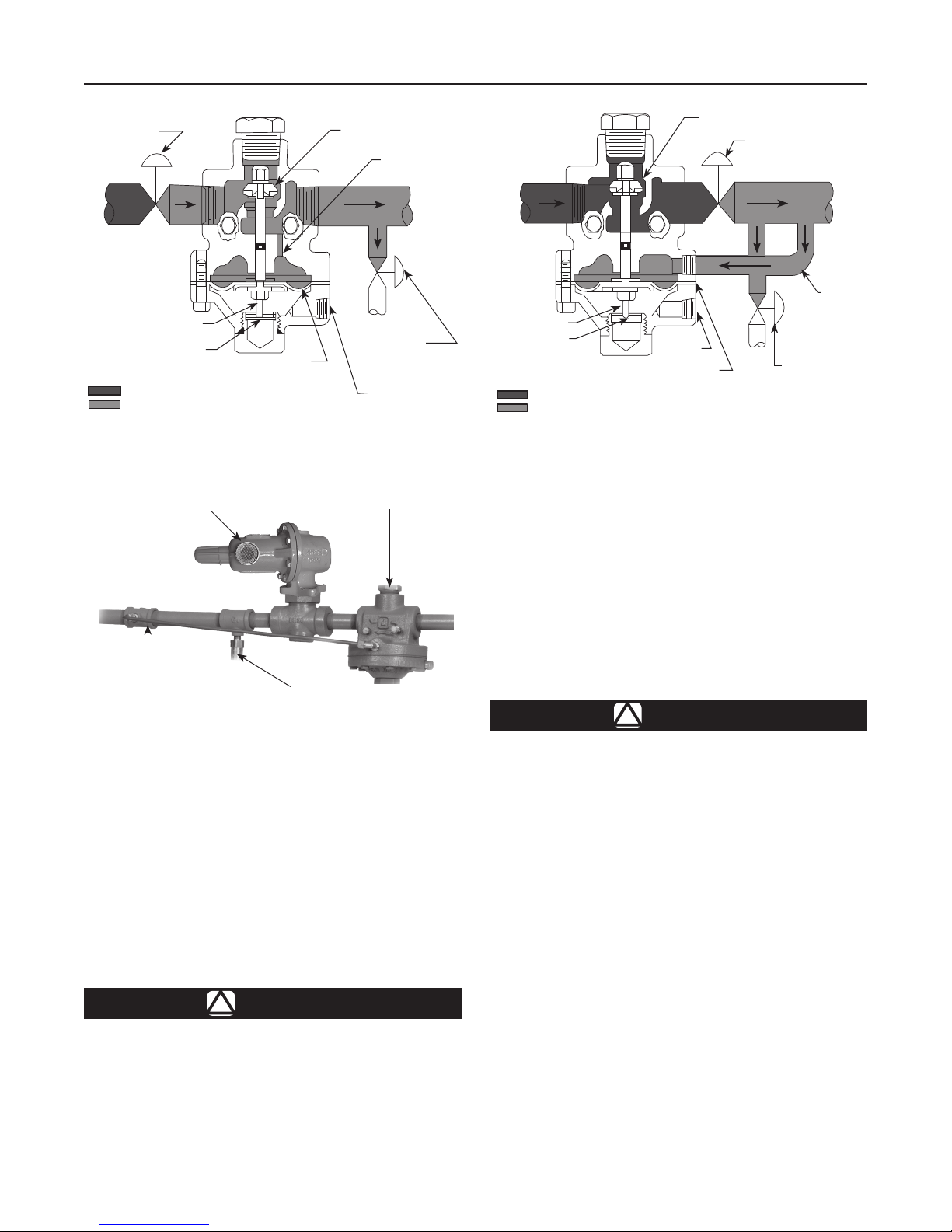
REDUCING
REGULATOR
FRACTURE DISK
INLET PRESSURE
OUTLET PRESSURE
STEM
DIAPHRAGM
PLUG ASSEMBLY
INTERNAL
REGISTRATION
TAP
OPTIONAL TOKEN
RELIEF VALVE
VENT
TAPPING
Figure 2. Type 634 Shutoff Valve Installation
TYPE 627 PRESSURE
REDUCING REGULATOR
W4263*
DOWNSTREAM
CONTROL LINE
OPTIONAL TYPE H120
TOKEN RELIEF VALVE
TYPE 634M
SHUTOFF VALVE
Figure 4. Typical Installation Showing Token Relief Valve
Therefore, inlet pressure to the upstream
reducing regulator must not exceed the maximum
emergency outlet pressure rating of that regulator
or 1500 psig / 103 bar, whichever is less.
5. The Type 634M shutoff valve installation shown
in Figure 3 will shut off flow to the downstream
reducing regulator. Thus, inlet pressure to that
regulator is limited by its maximum allowable
inlet pressure rating or by the Type 634M
maximum inlet pressure of 1500 psig / 103 bar,
whichever is less.
PLUG ASSEMBLY
REDUCING
REGULATOR
STEM
FRACTURE DISK
INLET PRESSURE
OUTLET PRESSURE
VENT
TAPPING
DIAPHRAGM
OPTIONAL TOKEN
RELIEF VALVE
Figure 3. Type 634M Shutoff Valve Installation
6. Both types can be used along with a token
relief valve (Figure 4) to minimize unnecessary
shutoff. The relief valve is set to open before the
Type 634 or 634M shutoff valve activates. This
arrangement allows the relief valve to handle
minor overpressure problems such as gas thermal
expansion or seat leakage due to dirt moving
through the system which may move out of the
regulator during the next operating cycle. The
shutoff valve does activate if the regulator has a
major malfunction with excessive gas flow that
exceeds the token relief capacity.
WARNING
!
In case the diaphragm leaks, a Type 634
or 634M shutoff valve can vent gas from
the vent assembly (key 22, not shown)
in the upper casing (key 2). If a Type 634
or 634M shutoff valve in ammable or
hazardous gas service is installed in
an enclosed space or a conned area,
personal injury or property damage
may occur due to re or explosion of
accumulated gas. To prevent such injury
or damage, provide piping or tubing to
remove the vented gas to a safe, wellventilated area at atmospheric pressure.
CONTROL
LINE
CAUTION
To avoid a pressure surge that may
shatter the fracture disk due to impact,
start up the system slowly.
7. A self-threading vent assembly (key 22, not
shown) is screwed into the 1/4 NPT tapping of
the casing. This vent assembly may be removed
and obstruction-free piping or tubing installed
for remote venting of the casing. If kept in the
casing, the vent assembly must be pointed down
if possible or otherwise protected from blockage
such as insects, snow or freezing rain.
3
Page 4

Types 634 and 634M
FRACTURE DISK SHATTER PRESSURE TO
TYPE 634M SHUTOFF VALVE, bar
1500
1250
1000
50
7
103
100
75
INLET PRESSURE TO
TYPE 634M SHUTOFF
VALVE, psig
A3328
Type 634 Shutoff Valve
psig bar
20 to 28 1.4 to 1.9
50 to 60 3.4 to 4.1
72 to 88 5.0 to 6.1
INLET PRESSURE TO
750
A B C
500
250
0
25 50 75 1000
FRACTURE DISK SHATTER PRESSURE
OF TYPE 634M SHUTOFF VALVE, psig
TYPE 634M SHUTOFF
50
25
0
VALVE, bar
Figure 5. Fracture Disk Selection
Table 1. Fracture Disk Selection
SHATTER PRESSURE FRACTURE DISK
Type 634M Shutoff Valve Color Code Part Number
20 to 28 psig / 1.4 to 1.9 bar at 0 psig / 0 bar inlet
pressure; see curve A for other inlet pressures
50 to 60 psig / 3.4 to 4.1 bar at 0 psig / 0 bar inlet
pressure; see curve B for other inlet pressures
72 to 88 psig / 5.0 to 6.1 bar at 0 psig / 0 bar inlet
pressure; see curve C for other inlet pressures
Red 29A1936X012
Yellow 29A1936X022
White 29A1936X032
Note
If using pipe in the following step, apply
pipe compound to the pipe threads
before making the connections.
8. Install tubing or piping into the 3/4 or 1 NPT
connections of the body. With a Type 634M shutoff
valve, also install a control line into the 1/4 NPT
control line connection in the body.
CAUTION
A closed Type 634 or 634M shutoff
valve means some other component
in the system, such as a reducing
regulator, is causing overpressure.
4
The malfunctioning component and
the overpressure condition must be
corrected before the fracture disk
is replaced.
9. The downstream pressure at which the fracture
disk shatters depends on the unbalance between
inlet and downstream pressure and can be
determined from Figure 5. This shatter pressure
is non-adjustable and can only be changed if the
disk is changed (Type 634) or if either the disk or
inlet pressure is changed (Type 634M). Fracture
disks (key 4) are color coded to indicate their
shatter pressure.
10. The Type 634 shutoff valve has negligible
unbalance because downstream pressure is
essentially the same as inlet pressure during
Page 5

Types 634 and 634M
normal operation. Simply select the fracture disk
(key 4) of the appropriate color from Figure 5
according to the desired shatter pressure.
11. The Type 634M shutoff valve can have
considerable unbalance, thus causing the shatter
pressure to vary approximately 2 psig / 0.14 bar
per every 100 psig / 6.9 bar of inlet pressure
change. Select the fracture disk (key 4) of the
appropriate color from Figure 5 according to the
desired shatter pressure in combination with the
inlet pressure.
Note
The lowest pressure of the fracture disk
(key 4) chosen according to step 10
or 11 must be higher than all normal
operating pressures of the regulator
and system being protected. Regulator
pressure characteristics such as
lockup, boost and proportional band
must be considered as part of normal
operating pressures.
Maintenance
All key numbers mentioned in this section appear in
Figure 6.
Types 634 and 634M shutoff valves are normally
open. They close only when the fracture disk (key 4)
shatters. Frequency of maintenance depends upon
the severity of service conditions and the requirements
of government regulations. Parts must be replaced
as necessary. Use only Emerson-authorized
replacement parts.
Preparing for Maintenance
1. Isolate the shutoff valve from both upstream and
downstream pressure.
2. Release trapped pressure from both the inlet and
outlet ends of the body (key 1) as follows:
• Where a pipe plug (key 15) is installed in the
body side tapping, use the valves provided in the
system to bleed off pressure. Do not unscrew the
pipe plug.
• Where a tank valve (key 15, not shown) is
installed in the body side tapping, remove the
tank valve cap. Push in on the tank valve stem
until all trapped pressure bleeds out, making
sure the gas bleeds to a safe location. Then,
replace the cap.
Replacing Fracture Disk
1. Complete the procedure for preparing
for maintenance.
2. Remove the disk retainer (key 3) from the upper
casing (key 2) and snap ring (key 14) from the
disk retainer.
3. Shake any loose fragments out of the disk retainer
(key 3), and remove any remaining fragments
from the upper casing (key 2) and body cavities
so as not to hinder diaphragm (key 6) action upon
reassembly. Install a new fracture disk (key 4) and
secure it with the snap ring (key 14). Remark the
disk retainer if the replacement fracture disk has a
range different from the range of the fracture disk
originally shipped from the factory.
WARNING
!
Personal injury or equipment damage
may be caused by sudden release of
pressure or explosion of accumulated
gas. To avoid such injury or damage,
isolate the shutoff valve from system
pressure and relieve all internal pressure
before starting disassembly. Releasing
downstream pressure from a closed
Type 634 or 634M shutoff valve does not
release inlet pressure from that shutoff
valve. Since there is no longer an intact
fracture disk in a shutoff valve that has
been closed, make sure no downstream
pressure is allowed to act on the
diaphragm during maintenance.
4. If necessary, replace the O-ring (key 21) used on
the disk retainer (key 3).
5. Apply a suitable thread lubricant to the threads
of the disk retainer (key 3), and install it into the
upper casing.
6. Test for leakage after assembly.
Replacing Plug Assembly, Diaphragm
or O-rings
1. Complete the procedure for preparing
for maintenance.
2. Remove the pipe plug, cap screws, upper casing
(key 2) and hex nut (keys 2, 11, 12 and 13) from
the fracture disk (key 4) end of the stem (key 10).
5
Page 6

Types 634 and 634M
3. Remove the other special washer, diaphragm
heads (keys 5, 7 and 23), diaphragm (key 6) and
O-rings from the fracture disk (key 4) end of the
stem (key 10).
4. Slide the stem (key 10) out to gain access to the
O-ring (key 8) in its center recess.
5. Remove the special hex nut, lockwasher, plug
assembly, O-ring and special washer (keys 7, 8, 9,
16 and 17) from the plug end of the stem (key 10).
6. Inspect and replace parts as necessary.
7. Lubricate the recessed area of the stem (key 10)
with a suitable lubricant and then install the O-ring
(key 8) into the recessed area.
8. Install one special washer (key 7), O-ring (key 8),
plug assembly (key 9), lockwasher (key 16) and
special hex nut (key 17) onto the appropriate end
of the stem (key 10) as shown in Figure 6. Insert
the plug and stem assembly into the body (key 1).
9. Install the following over the fracture disk end of
the stem:
• The lower diaphragm head (key 23) with its
chamfered side facing away from the plug
assembly, followed by an O-ring (key 8);
• The diaphragm, followed by another O-ring
(key 8);
• The diaphragm head (key 5) with its chamfered
side facing toward the plug assembly;
• The other special washer (key 7);
• The other hex nut (key 12). Good assembly
practice includes tightening both hex nuts
(keys 12 and 17) to 6 to 8 ft-lbs / 8 to
11 N•m torque.
10. Apply a suitable thread sealant to the threads of
the pipe plug (key 13), and install the pipe plug
into the body (key 1).
11. Install the upper casing (key 2) so that the vent
assembly (key 22, not shown) is pointed down or
otherwise protected.
12. Install the cap screws (key 11). Before tightening
them, make sure that the plug assembly (key 9)
is closed in order to provide enough slack in
the diaphragm.
13. Tighten the cap screws (key 11) using a crisscross
bolting pattern. Good assembly practice includes
tightening the cap screws to 13 to 17 ft-lbs / 18 to
23 N•m torque.
14. Make sure that the disk retainer (key 3) and
attached parts are installed into the upper casing
according to steps 3 through 5 of the replacing
fracture disk procedure.
Parts Ordering
When corresponding with a local Sales Ofce about
Types 634 and 634M shutoff valves, include the type
number and all other pertinent information stamped
on the disk retainer and casing. Specify the elevencharacter part number when ordering from the
following Parts List.
Parts List
Key Description Part Number
Repair Kits (included are keys 4, 6, 8,
9 and 21)
With red fracture disk R634X000012
With yellow fracture disk R634X000022
With white fracture disk R634X000032
1 WCC Steel Body
3/4 NPT
Type 634 39A1091X022
Type 634M 39A0584X022
1 NPT
Type 634 39A1090X032
Type 634M 39A0585X022
2 Upper Casing
Cast iron 29A0776X012
3* Disk Retainer
Steel 19A1935X022
4* Fracture Disk, Cast iron
Red color code 29A1936X012
Yellow color code 29A1936X022
White color code 29A1936X032
5 Diaphragm Head
Plated steel 19A1937X012
6* Diaphragm
Neoprene (CR) and Nylon (PA) fabric 19A1938X012
7 Special Washer
Plated steel (2 required) 19A1940X012
8* O-ring, Nitrile (NBR) (4 required) 1D6875X0022
9* Plug Assembly
Aluminum and Nitrile (NBR) 19A1943X012
10 Stem, Stainless steel 19A1941X012
11 Cap Screw, Plated steel (8 required) 1B787724052
12 Hex Nut, Steel 1A345724122
13 Pipe Plug, Plated steel 1A794728992
14 Snap Ring 12B9220X012
15 Pipe Plug, Plated steel (2 required
with standard construction or 1 required
with Tank Valve Inlet only) 1A500828992
15 Tank Valve (not shown), Plated steel
(1 required with Tank Valve Inlet only
or 2 required with standard construction 19A1951X012
16 Lockwasher, Plated carbon steel 1C225628982
17 Special Hex Nut, Stainless steel 19A1944X012
21* O-ring, Nitrile (NBR) 10A8931X012
22 Type Y602-12 Vent Assembly (not shown)
Plastic 27A5516X012
23 Lower Diaphragm Head
Plated steel 19A6901X012
*Recommended spare part.
6
Page 7

Types 634 and 634M
15
TORQUE:
6 TO 8 FT-LBS /
8 TO 11 N•m
29A1948-DA
L3
23
6
5
8
L1
2
TORQUE:
11
13 TO 17 FT-LBS /
18 TO 23 N•m
12
L2
3
14
4
21
DETAIL OF TYPE 634 SHUTOFF VALVE
1
16
9
13
L3
TORQUE:
17
6 TO 8 FT-LBS /
8 TO 11 N•m
8
7
15
L3
23
6
5
TORQUE:
6 TO 8 FT-LBS /
12
8 TO 11 N•m
L2
29A1947-DA
APPLY LUBRICANT
L1 = MULTI-PURPOSE LITHIUM POLYMER LUBRICANT
L2 =ALUMINUM ANTI-SEIZE LUBRICANT
L3 = ZINC-BASED ANTI-SEIZE LUBRICANT
1. Lubricants must be selected such that they meet the temperature requirements.
(1)
:
3
COMPLETE TYPE 634M SHUTOFF VALVE
Figure 6. Types 634 and 634M Assemblies
10
8
L1
2
11
TORQUE:
13 TO 17 FT-LBS /
18 TO 23 N•m
14
4
21
7
Page 8

Types 634 and 634M
Webadmin.Regulators@emerson.com
Fisher.com
Emerson Automation Solutions
Americas
McKinney, Texas 75070 USA
T +1 800 558 5853
Asia Pacic
Singapore 128461, Singapore
T +65 6777 8211
+1 972 548 3574
Europe
Bologna 40013, Italy
T +39 051 419 0611
Middle East and Africa
Dubai, United Arab Emirates
T +971 4 811 8100
Facebook.com/EmersonAutomationSolutions
LinkedIn.com/company/emerson-automation-solutions
Twitter.com/emr_automation
D100638X012 © 1984, 2018 Emerson Process Management Regulator
Technologies, Inc. All rights reserved. 12/18.
The Emerson logo is a trademark and service mark of Emerson
Electric Co. All other marks are the property of their prospective owners.
Fisher™ is a mark owned by Fisher Controls International LLC, a
business of Emerson Automation Solutions.
The contents of this publication are presented for information purposes
only, and while effort has been made to ensure their accuracy, they are
not to be construed as warranties or guarantees, express or implied,
regarding the products or services described herein or their use or
applicability. All sales are governed by our terms and conditions, which
are available on request. We reserve the right to modify or improve the
designs or specications of our products at any time without notice.
Emerson Process Management Regulator Technologies, Inc. does not
assume responsibility for the selection, use or maintenance of any
product. Responsibility for proper selection, use and maintenance of any
Emerson Process Management Regulator Technologies, Inc. product
remains solely with the purchaser.
 Loading...