

Page 1
Instruction Manual
D103425X012
546NS Transducer
Fisherr 546NS Electro‐Pneumatic Transducer
April 2015
Contents
Introduction 1.................................
Scope of Manual 1.............................
Description 2.................................
Specifications 3...............................
564NS Qualification 3......................
Educational Services 3.........................
Installation 5..................................
Hazardous Area Classifications 5.................
Mounting 6..................................
Pressure Connections 6........................
Diagnostic Connections 7......................
Electrical Connections 8........................
Operating Information 9.........................
Adjustments 9................................
Calibration 10................................
Equipment Required 10.....................
Calibration Procedure 10....................
Recalibration 11...........................
Changing Output Pressure Range 12.............
Reversing the Action 12........................
Split Range Operation 12.......................
Principle of Operation 13........................
Maintenance 14................................
Relay Removal and Replacement 15..............
Replacing the Feedback Bellows Assembly 15......
Troubleshooting 16............................
Electrical 16..............................
Pneumatic 16.............................
Alignment 17.................................
Span Adjustment 17.......................
Torque Motor Frame 18....................
Armature Travel Stop 18....................
Coil 18...................................
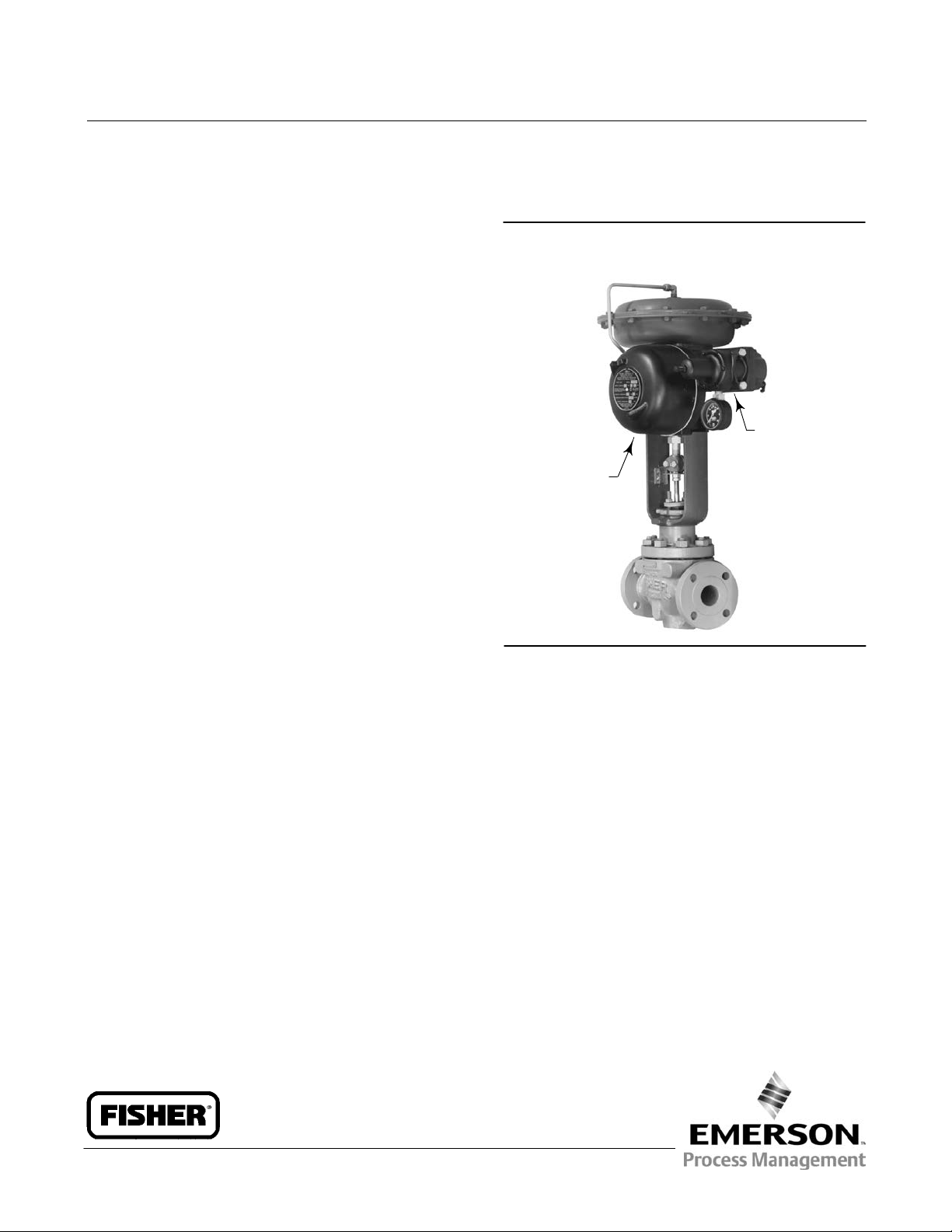
Figure 1. Fisher 546NS Electro‐Pneumatic Transducer
Mounted on a 657 Pneumatic Diaphragm Actuator
FILTER
REGULATOR
546NS
W2115
Parts Ordering 19...............................
Repair Kits 19..................................
Parts List 19...................................
Transducer 19................................
Torque Motor 20..............................
Relay 22.....................................
Mounting Parts 23.............................
Diagnostic Connections 23.....................
Introduction
Scope of Manual
This instruction manual provides installation, operation, maintenance, and parts ordering information for the Fisher
546NS transducer and the 82 relay. Refer to separate manuals for instructions covering equipment used with the
transducer.
www.Fisher.com
Page 2

546NS Transducer
April 2015
Do not install, operate or maintain a 546NS transducer without being fully trained and qualified in valve, actuator and
accessory installation, operation and maintenance. To avoid personal injury or property damage it is important to
carefully read, understand, and follow all of the contents of this manual, including all safety cautions and warnings.
If you have any questions about these instructions, contact your Emerson Process Management sales office
Business Partner before proceeding.
Instruction Manual
D103425X012
or Local
Description
The 546NS transducer (figure 1) receives a current (mA DC) input signal and transmits a proportional pneumatic
output pressure to a final control element. A typical application is in electronic control loops where the final control
element, generally a control valve, is pneumatically operated. The input signal, output pressure range, and electrical
classification, if approved, of each transducer is indicated on the nameplate attached to the cover.
The 546NS transducer is designed for nuclear power applications. The 546NS construction includes materials that
provide superior performance in elevated temperature and radiation environments.
The O‐rings are EPDM (ethylene propylene) and the diaphragms are EPDM/NOMEXt. EPDM demonstrates superior
temperature capability and shelf life over nitrile. The NOMEX diaphragm fabric demonstrates improved strength
retention at elevated temperature and radiation conditions.
CAUTION
Use a clean, dry, oil‐free air supply with instruments containing EPDM components. EPDM is subject to degradation when
exposed to petroleum‐based lubricants.
Under the 10CFR50, Appendix B, quality assurance program, the 546NS transducer is qualified “commercial grade
dedicated”. These can be supplied as 10CFR, Part 21 items.
2
Page 3

Instruction Manual
D103425X012
546NS Transducer
April 2015
Specifications
Specifications are listed in table 1.
546NS Qualification
The 546NS is qualified to meet stringent environmental conditions encountered in nuclear power plant containment
areas. Samples were subjected to the tests summarized below:
D Thermal Aging: accelerated service temperature of 54_C (130_F) over 10 years.
D Radiation Aging: 6 MRads Total Integrated Dose (TID)
D Seismic Event Simulation (DBE): no natural frequencies found between 5‐100 Hz and seismic dwells of 8g uniaxial
from 3‐40 Hz.
D LOCA/MSLB Event Simulation: saturated steam for 14 hours at 160_C ( 320_F) followed by a gradual reduction to
83_C (182_F) over a 10 hour period.
Upon conclusion of the above tests, no loss of function or extreme degradation was found.
Educational Services
For information on available courses for the 546NS transducer, as well as a variety of other products, contact:
Emerson Process Management
Educational Services, Registration
Phone: +-1-641-754-3771 or +1-800-338-8158
e-mail: education@emerson.com
http://www.emersonprocess.com/education
3
Page 4

546NS Transducer
April 2015
Table 1. Specifications
Instruction Manual
D103425X012
Available Configuration
Electro‐pneumatic signal transducer with
explosion‐proof case and cover, with EPDM
elastomers for use in elevated temperature and
radiation environments
The 546NS can be ordered with or without a Fisher 67
filter regulator. A 51 mm (2 inch) circular supply
pressure gauge may be mounted on the regulator.
Input Signals
J 4 to 20 mA DC, J 10 to 50 mA DC, or J two‐way
split range using any half of one of the standard input
signal spans
Internal Resistance of Torque Motor
4 to 20 mA DC Input Signal: 176 ±10 ohms
10 to 50 mA DC Input Signal: 90 ±10 ohms
Output Signals
Ranges:
0.2 to 1.0 bar (3 to 15 psig), 0.4 to 2.0 bar
(6 to 30 psig)
Action: 546NS is field‐reversible between direct and
reverse action.
Supply Pressure
(1)
Recommended: 0.3 bar (5 psig) higher than upper
range limit of output signal
Maximum: 3.5 bar (50 psig)
Performance
(3)
Actuator Loading Time: See figure 6
(4)
Reference Accuracy
: ±0.75% of the output span
Independent Linearity: ±0.50% of the output span
Open Loop Gain: 26
Frequency Response: Gain is attenuated 3 dB at 20 Hz
with transducer output signal piped to a typical
instrument bellows with 305 mm (12 inches) of
1/4 inch tubing
Electromagnetic Interference (EMI): Tested per IEC
61326‐1 (Edition 1.1). Meets emission levels for Class
A equipment (industrial locations) and Class B
equipment (domestic locations). Meets immunity
requirements for industrial locations (Table A.1 in the
IEC specification document). Immunity performance
shown in table 2.
Operative Ambient Temperature Limits
(1)
-40 to 66_C (-40 to +150_F)
Electrical Classification
Hazardous Area:
CSA— Explosion-proof, Dust Ignition‐proof, Div 2
FM— Explosion-proof, Dust Ignition‐proof,
Non‐incendive
Refer to table 3 and 4 for specific approval
information.
NEMA 3R, CSA enclosure 3
NEMA 3R mounting orientation requires vent location
to be below horizontal. Vent is shown in figure 9, key
69.
Maximum Steady‐State Air Consumption
At 1.4 bar (20 psig) Supply Pressure:
0.6 normal m
3
/hr (21 scfh)
At 2.4 bar (35 psig) Supply Pressure:
0.8 normal m
Maximum Output Air Capacity
3
/hr (30 scfh)
(2)
At 1.4 bar (20 psig) Supply Pressure:
3
12.9 normal m
At 2.4 bar (35 psig) Supply Pressure:
18.5 normal m
4
/hr (480 scfh)
3
/hr (690 scfh)
(2)
Adjustments
Zero and Span Adjustments: Screwdriver adjustments
located inside case (see figure 4)
Connections
Supply Pressure: 1/4 NPT internal located on side of
case, (or located on the 67CFR filter‐regulator if
mounted)
Output Pressure: 1/4 NPT internal located on side of
case
Vent: 1/4 NPT internal with screen located on relay
Electrical: 1/2 NPT internal located on bottom of case
-continued-
Page 5

Instruction Manual
D103425X012
Table 1. Specifications (continued)
546NS Transducer
April 2015
Approximate Weight
4.1 kg (9 pounds)
3 of the Pressure Equipment Directive (PED) 97 / 23 /
EC. It was designed and manufactured in accordance
with Sound Engineering Practice (SEP) and cannot
bear the CE marking related to PED compliance.
Declaration of SEP
Fisher Controls International LLC declares this
product to be in compliance with Article 3 paragraph
NOTE: Specialized instrument terms are defined in ANSI/ISA Standard 51.1 - Process Instrument Terminology.
1. The pressure/temperature limits in this document and any applicable standard or code limitation should not be exceeded.
2. Normal m
3. Performance values are obtained using a 546 transducer with a 4 to 20 mA DC input signal and a 0.2 to 1 bar (3 to 15 psig) or a 0.4 to 2 bar (6 to 30 psig) output signal. Ambient temperature
is 24_C (73_F). A transducer with other input or output signals might exceed these values. Reference accuracies of ±3.5% can be expected with output ranges starting near zero psig.
4. Reference accuracy includes the effects of non-linearity, hysteresis, and deadband per SAMA Standard PMC 20.1-1973.
3
/hr—Normal cubic meters per hour (0_C and 1.01325 bar absolute). Scfh—Standard cubic feet per hour (60_F and 14.7 psia).
However, the product may bear the CE marking to
indicate compliance with other applicable European
Community Directives.
Table 2. Electromagnetic Immunity Performance
Port Phenomenon Basic Standard Test Level Performance Criteria
Electrostatic discharge (ESD) IEC 61000‐4‐2
Enclosure
I/O signal/control
Specification limit = ±1% of span
1. A=No degradation during testing. B = Temporary degradation during testing, but is self‐recovering.
Radiated EM field IEC 61000‐4‐3
Rated power frequency magnetic field IEC 61000‐4‐8 60 A/m at 50 Hz A
Burst (fast transients) IEC 61000‐4‐4 1 kV A
Surge IEC 61000‐4‐5 1 kV (line to ground only, each) B
Conducted RF IEC 61000‐4‐6
4 kV contact
8 kV air
80 to 1000 MHz @ 10V/m with 1
kHz AM at 80%
150 kHz to 80 MHz at 3 Vrms with
1kHz AM at 80%
A
A
A
(1)
Installation
WARNING
Avoid personal injury from sudden release of process pressure. Before mounting the controller:
D Always wear protective clothing, gloves, and eyewear when performing any installation operations to avoid personal
injury.
D Check with your process or safety engineer for any additional measures that must be taken to protect against process
media.
D If installing into an existing application, also refer to the WARNING at the beginning of the Maintenance section in this
instruction manual.
Hazardous Area Classifications
Certain nameplates may carry more than one approval, and each approval may have unique installation/wiring
requirements and/or conditions of “safe use”. These special instructions for “safe use” are in addition to, and may
override, the standard installation procedures. Special instructions are listed by approval.
5
Page 6

546NS Transducer
April 2015
Note
This information supplements the nameplate markings affixed to the product.
Always refer to the nameplate itself to identify the appropriate certification. Contact your Emerson Process Management sales
office for approval/certification information not listed here.
Instruction Manual
D103425X012
CSA and FM
No special conditions of safe use.
Refer to table 3 and 4 for approval information.
Table 3. Hazardous Area Classifications—CSA (Canada)
Certification Body Certification Obtained Temperature Code
CSA
Explosion-proof
Class I, Division 1, Group C,D
Class II, Division 1, Groups E,F,G
Class I, Division 2, Groups A,B,C,D
Class II, Division 2, Groups F,G
T5 (Tamb = 66_C)
T5
Table 4. Hazardous Area Classifications— FM (United States)
Certification Body Certification Obtained Temperature Code
FM
Explosion-proof
Class I, Division 1, Groups C,D
Class II, Division 1, Groups E,F,G
Class I, Division 2, Groups A,B,C,D
Class II, Division 2, Groups F,G
T5 (Tamb = 60_C)
T5
Mounting
When a 546NS transducer is ordered as part of a control valve assembly, the factory mounts the transducer on the
actuator and connects the necessary tubing, then adjusts the transducer as specified on the order.
Transducers also can be ordered separately for mounting on a control valve assembly already in service. The
transducer may be ordered with or without mounting parts. Mounting parts include the appropriate bracket and bolts
for attaching the unit to an actuator boss (with tapped holes) or for attaching it to the diaphragm casing. If preferred,
mounting parts are available for mounting the transducer on a 51 mm (2 inch) diameter pipestand, a flat surface, or a
bulkhead.
Tubing is not included if the transducer is not factory mounted. Use 9.5 mm (3/8‐inch) outside diameter tubing for all
supply and output connections. Tubing length between the transducer output and the final control element should be
as short as possible to minimize its effect on control loop stability.
Pressure Connections
WARNING
Severe personal injury or property damage may occur if the instrument air supply is not clean, dry and oil‐free. While use
and regular maintenance of a filter that removes particles larger than 40 micrometers in diameter will suffice in most
applications, check with an Emerson Process Management field office and industry instrument air quality standards for use
with corrosive air or if you are unsure about the proper amount or method of air filtration or filter maintenance.
6
Page 7
Instruction Manual
D103425X012
546NS Transducer
April 2015
Note
The supply source must be clean, dry, oil‐free, non‐corrosive air at an unfailing pressure at least 0.3 bar (5 psig) higher than the
upper limit of the transducer output pressure range. This means that for an output pressure range of 0.2 to 1.0 bar (3 to 15 psig)
the supply pressure should be at least 1.4 bar (20 psig); for a 0.4 to 2.0 bar (6 to 30 psig) range, the supply pressure should be at
least 2.4 bar (35 psig). The supply pressure to the filter regulator should not be more than 17.3 bar (250 psig) at a maximum
temperature of 66_C (150_F).
If specified, the filter regulator is mounted on the transducer case. A pressure gauge on the regulator shows the supply
pressure to the transducer.
1. Connect a supply pressure source to the 1/4 NPT IN connection on the filter regulator (if furnished) or to the 1/4
NPT SUPPLY connection on the transducer case (if a regulator is not furnished).
2. Run 9.5 mm (3/8‐inch) outside diameter tubing from the 1/4 NPT OUTPUT connection on the transducer case to
the input connection on the pneumatic actuator or valve positioner. This connection is made at the factory if the
unit is shipped mounted on an actuator as shown in figure 1.
Diagnostic Connections
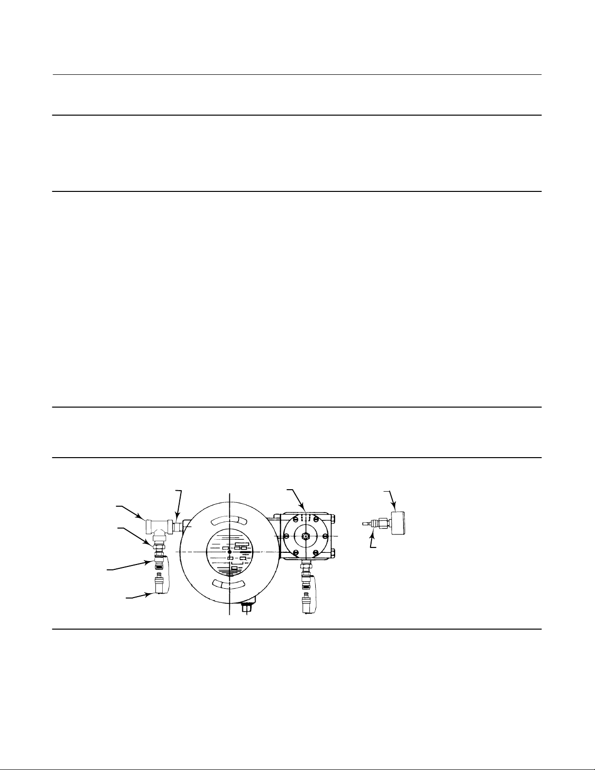
To support diagnostic testing of valve/actuator/positioner packages, special connectors and hardware are available.
Typical connector installations are shown in figure 2. The hardware used includes a 1/4 NPT pipe nipple and pipe tee
with a 1/8 NPT pipe bushing for the connector. The connector consists of 1/8 NPT body and body protector.
Note
If the transducer is used in a valve assembly with a positioner, no connections for diagnostic testing are required for the
transducer. Install the connections for diagnostic testing at the positioner.
Figure 2. Diagnostic Connections
PIPE NIPPLE (OUTPUT CONN)
PIPE TEE
PIPE
BUSHING
BODY
BODY
PROTECTOR
12B8041‐B
A6072‐1
SUPPLY
GAUGE
STEM PROVIDED
WHEN GAUGE
IS SPECIFIED
Install the connectors and hardware between the transducer and the actuator.
1. Before assembling the pipe nipple, pipe tee, pipe bushings, actuator piping, and connector body, apply sealant to
all threads.
2. Turn the pipe tee to position the connector body and body protector for easy access when doing diagnostic testing.
7
Page 8

546NS Transducer
April 2015
Instruction Manual
D103425X012
Electrical Connections
WARNING
For explosion‐proof applications, disconnect power before removing the transducer cover. Personal injury or property
damage may result from fire or explosion if power is applied to the transducer with the cover removed in a hazardous area.
Also refer to the Warning at the beginning of the Operating Information section.
For explosion‐proof applications, install rigid metal conduit and a conduit seal no more than 457 mm (18 inches) from the
transducer. Personal injury or property damage may result from explosion if the seal is not installed.
Select wiring and/or cable glands that are rated for the environment of use (such as hazardous area, ingress protection, and
temperature). Failure to use properly rated wiring and/or cable glands can result in personal injury or property damage
from fire or explosion.
Wiring connections must be in accordance with local, regional, and national codes for any given hazardous are approval.
Failure to follow the local, regional, and national codes could result in personal injury or property damage from fire or
explosion.
The electrical connections are made in the transducer case. A 1/2 NPT conduit connection is provided in the bottom of
the case. Use a suitable conduit seal for hazardous locations. The wires that carry the input signal from the control
device are connected to the terminal mounting bracket assembly (key 53, figure 8).
For a direct‐acting unit (i.e., increasing current produces an increasing output pressure), connect the positive wire
from the control device to the positive terminal of the transducer and the negative wire to the negative terminal. For a
reverse‐acting unit (i.e., increasing current produces a decreasing output pressure), connect the positive wire from the
control device to the negative terminal and the negative wire to the positive terminal. Typical circuits are shown in
figure 3.
Figure 3. Typical Circuit Drawings
NOTE:
1 DC RESISTANCE OF COILS
CP8401‐B
B1766‐2
+
INPUT
-
DC SIGNAL: 4 TO 20 MILLIAMPS
1
176 OHMS
+
INPUT
-
DC SIGNAL: 10 TO 50 MILLIAMPS
1
90 OHMS
CAUTION
Use a lubricant (key 95, figure 7) on the case‐cover threads to prevent thread damage.
8
Page 9

Instruction Manual
D103425X012
546NS Transducer
April 2015
Operating Information
WARNING
Personal injury or property damage may result from fire or explosion if power is applied to the transducer with the cover
removed in a hazardous area.
If the transducer is installed in an application where explosion‐proof classification is required, perform the following steps
(prior to removal of the transducer cover) when any procedure in this section requires removal of the cover:
D Disconnect the electrical signal from the transducer.
D Remove the transducer to a non‐hazardous area.
D Perform procedures as described in this section.
D Reinstall the transducer, and ensure the cover is secured before turning on the electrical signal.
Adjustments
Adjust the filter regulator to provide the proper supply pressure to the transducer, then adjust the transducer span and
zero (see figures 4 and 5) to match the application requirements and be within specifications.
Figure 4. Zero and Span Adjustments (Cover Removed)
ZERO ADJUSTMENT
SPAN ADJUSTMENT
W5391/IL
The zero adjustment is used to set the output pressure so that it corresponds to the proper value of the input signal.
For example, if the output range is 0.2 to 1.0 bar (3 to 15 psig) and the input range is 1 to 5 mA DC and the unit is
direct‐acting, use the zero adjustment to set the output pressure at 0.2 bar (3 psig) when the input signal is 1 mA DC.
Use the span adjustment to set the output pressure span so that full output pressure change results for a full change in
the input signal. In this example, the output pressure change would be 0.8 bar (12 psi). Thus, the output pressure
should start at 3 psig and increase to 1.0 bar (15 psig) as the input signal is changed from 1 to 5 mA DC.
A span adjustment will affect the zero. Therefore, follow any span adjustment with a zero adjustment. Provide a
suitable gauge to measure the pressure.
9
Page 10

546NS Transducer
April 2015
Instruction Manual
D103425X012
Calibration
Equipment Required
Choose a current source that is capable, without switching ranges, of driving the transducer through its entire input
range. Switching ranges on a current source will produce spikes or mid‐scale reverses in the input signal presented to
the transducer, causing errors.
Calibration Procedure
Note
The following calibration procedure is for a 546NS transducer with a 4 to 20 mA DC input signal range and a 0.2 to 1.0 bar (3 to 15
psig) output range. Calibrate transducers with other inputs and outputs in a similar manner.
1. Check the supply pressure to ensure it agrees with the minimum pressure on the transducer nameplate.
2. Adjust the input current to 4.00 mA DC.
3. Turn the zero screw until the output pressure is 0.2 ±0.006 bar (3.00 ±0.09 psig).
4. Adjust the input to 20.00 mA DC.
5. If the output pressure is less than 1.028 bar (14.91 psig), turn the span screw clockwise to increase the span. If the
output pressure is greater than 1.040 bar (15.09 psig), turn the span screw counterclockwise to decrease the span.
Note
Do not watch the output gauge while turning the span screw because the change in output is not a good indication of the change
in span. While turning the span adjustment screw, the output pressure may move in the opposite direction than expected. For
example, while turning the span screw in the INCREASING SPAN direction, the output pressure might decrease.
This should be disregarded since even though the output pressure decreases, the output span is increasing.
6. Repeat steps 2 through 5 until the output pressure is within one‐third of the accuracy limits at 4 and 20 mA DC.
One‐third of the accuracy limits for a 0.2 to 1.0 bar (3 to 15 psig) output range is 1/3 (±0.0075) (15.00 - 3.00) =
±2 mbar (±0.03 psig). Calibrate for maximum accuracy at the target end points [0.20 and 1.00 bar (3.00 and 15.00
psig)]. This allows for error at other calibration points in between.
7. Run the transducer through three calibration cycles before recording data. The cycles should be run from exactly
4.00 to 20.00 mA DC in a slow ramping fashion (no large step inputs).
8. After returning from 20.00 mA DC during the last exercise cycle, move back upscale to the midpoint (12.00 mA DC)
and record the first data point. Table 5 is an example of recorded data.
9. Record at the other calibration points desired by moving upscale to 20.00 mA DC then down scale to 4.00 mA DC,
then back upscale to 12.00 mA DC. Refer to table 5 for common calibration points.
10
Page 11

Instruction Manual
D103425X012
546NS Transducer
April 2015
CAUTION
Reversing the DC input during the calibration cycle may result in product damage.
Note
During the calibration cycle, use care to avoid overshoot. In other words, if data is to be recorded at an 8.00 mA DC input while
moving upscale and you accidently pass 8.00 to some higher value, run the test again starting at step 7 with the three exercise
cycles. Do not reverse direction and move down scale to 8.00 mA DC.
10. After completing the calibration cycle and recording data, verify that all data is within ±0.75% accuracy limits. If not,
the transducer may need to be recalibrated to move the end points slightly to bring the entire calibration curve
within the accuracy limits.
Recalibration
Table 5 shows typical recorded data where recalibration is necessary.
Table 5. Typical Calibration Data
TRANSDUCER INPUT ACTUAL OUTPUT PRESSURE TARGET OUTPUT PRESSURE
mA DC Bar Psig Bar Psig
12.00
16.00
20.00
16.00
12.00
8.00
4.00
8.00
12.00
0.612
0.823
1.035
0.828
0.617
0.413
0.207
0.409
0.618
8.89
11.95
15.02
12.02
8.96
6.00
3.01
5.95
8.97
0.620
0.826
1.033
0.826
0.620
0.413
0.206
0.413
0.620
9.00
12.00
15.00
12.00
9.00
6.00
3.00
6.00
9.00
The 0.612 bar (8.89 psig) value at 12.00 mA DC is outside the accuracy limit of ±0.09 from the target value. This data
point can be raised by recalibrating the transducer and raising the end points enough to bring this low value within
-0.6 mbar (-0.09 psig) of 0.62 bar (9.00 psig). A reasonable recalibration would be 0.21 and 1.04 bar (3.05 and 15.05
psig) at 4.00 mA DC and 20.00 mA DC, respectively. Recalibrate the instrument and recheck the calibration data as
described in steps 7 through 10.
If the transducer remains outside of accuracy specifications after altering the calibration end points as much as
possible consult your Emerson Process Management sales office
.
For transducers inaccurate to less than 5 percent of output span, relay repair or replacement may correct the problem.
Refer to the alignment procedures in the Troubleshooting section to correct the operation of a faulty transducer. Also
check for air leaks at the tubing, nozzle, relay, and bellows.
If the accuracy error is greater than 5 percent of output span, check the clearance between the armature and the coils.
These parts are referenced as key 40 and key 42, respectively, in the Parts List section. The armature and the white
plastic coil bobbin should be approximately 0.4 mm (1/64 inch) apart. If the parts are in contact, loosen the machine
screws that hold the bobbin and reposition the bobbin.
11
Page 12

546NS Transducer
April 2015
Instruction Manual
D103425X012
Changing Output Pressure Range
Changing the output pressure range from 0.2 to 1.0 bar (3 to 15 psig) to 0.4 to 2.0 bar (6 to 30 psig) or vice versa
requires changing the feedback bellows (key 57, figure 8). To do this, refer to the replacing the feedback bellows
assembly procedures in the Maintenance section.
Note
Re‐magnetization of the torque motor is required when changing the output pressure range.
Reversing the Action
Reversing the action of a 546NS transducer requires no special parts. The direction of armature rotation is dependent
upon the direction of the current flow. Therefore, simply reverse the input current leads to the transducer to obtain
the opposite action. Whenever the action is changed, readjust the zero of the transducer as outlined in the
adjustments procedures.
Split Range Operation
The 546NS transducer is suitable for two‐way split range operation. In a two‐way split the milliampere (mA) or voltage
output signal of a single control device is split between two transducers electrically connected in series. Although each
transducer receives the full signal, it is calibrated to provide a full output pressure range of 0.2 to 1.0 bar (3 to 15 psig)
or 0.4 to 2.0 bar (6 to 30 psig) to the control valve with one‐half the input signal. Since the transducer operates on only
one‐half of the normal input span, the feedback bellows must be changed to compensate for the shorter span. Change
the bellows as described in the replacing feedback bellows assembly procedure in the Maintenance section. Table 6
indicates which bellows is required for your conditions. Reset the span and zero adjustments to the split range values.
Note that these transducers cannot provide a three‐way split range.
Table 6. Feedback Bellows Output Pressure Range
BELLOWS SIZE
OPERATION INPUT SIGNAL, DC
Full Range
Split Range
4 to 20 mA
10 to 50 mA
4 to 12 mA or 12 to 20 mA
10 to 30 mA or 30 to 50 mA
0.2 to 1.0 3 to 15 0.4 to 2.0 6 to 30 - - - - - -
Full Half Quarter
Bar Psig Bar Psig Bar Psig
- - - - - - 0.2 to 1.0 3 to 15 0.4 to 2.0 6 to 30
12
Page 13

Instruction Manual
D103425X012
546NS Transducer
April 2015
Principle of Operation
Refer to the schematic drawing in figure 5. Assume that the transducer is direct‐acting. An increase in the DC signal to
the coils increases the magnetic field around the coils. This field increases the magnetic strength in the armature and
the magnetic attraction across the air gap between the armature and the pole pieces.
The pole pieces are already polarized by the permanent magnet. The armature polarity is as shown in the schematic.
The magnetic attraction will therefore be downward at the nozzle end and upward at the feedback bellows end,
resulting in a torque that rotates the armature about the fixed torsion rod to cover the nozzle. The resulting restriction
produces an increased pressure in the nozzle, in the upper chamber of the relay, and in the feedback bellows. The relay
responds to the increase in nozzle pressure to increase the output pressure to the actuator and control valve. The
increased pressure in the feedback bellows creates a force that acts on the armature to move it back to an equilibrium
position. In this way, the new nozzle pressure is compared to the input current by the force‐balance principle.
The relay operates in the following manner. The nozzle pressure acts on the large top diaphragm to force the center
spacer assembly (mounted between the two diaphragms) downward against the valve plug, closing the exhaust port
and opening the supply port. Supply air then flows through the open port to the output load. The output pressure
continues to increase until the relay diaphragm assembly is pushed back to its original position by the force of the
pressure acting on the small diaphragm. When this occurs, the valve plug is closed again.
When a decreasing DC signal is received, the magnetic attraction across the air gap is reduced. The armature rotates
to uncover the nozzle and decrease the pressure in the nozzle, relay, and feedback bellows. The relay diaphragm
assembly moves upward, and the exhaust port opens to bleed the output pressure to atmosphere.
Figure 5. Transducer Schematic
FEEDBACK
BELLOWS
POLE
PIECES
COIL
ARMATURE
TORSION ROD
EXHAUST
OUTPUT
RELAY
VALVE PLUG
SPAN ADJUSTMENT
(MAGNETIC SHUNT)
ZERO ADJUSTMENT
PERMANENT
MAGNET
ARMATURE
NOZZLE
OUTPUT PRESSURE
NOZZLE PRESSURE
SUPPLY PRESSURE
EXHAUST PRESSURE
CENTER SPACER ASSEMBLY
FIXED
RESTRICTION
CP4285-A
A1505-3
SUPPLY
13
Page 14

546NS Transducer
April 2015
Instruction Manual
D103425X012
The output decreases until the diaphragm assembly is forced back to its original position and the exhaust port is closed
again. The reduced pressure in the feedback bellows diminishes the force to return the armature to the equilibrium
position.
Figure 6 shows output‐time relationship curves for loading and exhausting an actuator. Exhausting times are
nominally 25 percent of the loading times.
Figure 6. Output‐Time Relationship
100
90
80
70
60
50
OUTPUT
40
30
20
10
(% OF 546NS OUTPUT SPAN)
0
19A1361‐A
A3103
0 102030405060708090
LOADING
EXHAUSTING
100
TIME (%)
Reverse‐acting transducers operate in a similar manner except that when the DC input signal increases, the output
pressure from the relay decreases. Conversely, a decreasing input signal increases the output pressure.
Maintenance
Maintenance of the transducer consists of relay and feedback bellows replacement.
WARNING
The following maintenance procedures require that the transducer be taken out of service. This requires that certain
precautions be taken to avoid personal injury or equipment damage caused by sudden release of pressure. Prior to
maintenance:
D Always wear protective clothing, gloves, and eyewear when performing any maintenance procedures to avoid personal
injury.
D Disconnect electrical power before removing the transducer cover.
D Shut off or disconnect pressure lines to the transducer.
D Disconnect any operating lines providing air pressure, electrical power, or a control signal to the actuator. Be sure the
actuator cannot suddenly open or close the valve.
D Use bypass valves or completely shut off the process to isolate the valve from process pressure.
D Do not remove the actuator from the valve while the valve is still pressurized.
D Relieve process pressure on both sides of the valve.
D Vent the power actuator loading pressure and relieve any actuator spring precompression.
D Use lock‐out procedures to be sure that the above measures stay in effect while you work on the equipment.
D Check with your process or safety engineer for any additional measures that must be taken to protect against process
media.
14
Page 15

Instruction Manual
D103425X012
546NS Transducer
April 2015
WARNING
For explosion proof applications, disconnect power before opening the transducer cover. Personal injury or property
damage may result from fire or explosion if power is not disconnected.
CAUTION
The presence of Emerson Process Management personnel and also approval agency personnel may be required if you
service (other than normal, routine maintenance, such as calibration) or replace components on a transducer that carries a
third‐party approval. When you replace components, use only components specified by the factory. Substitution with
other components may void the third‐party approval. Also, always use proper component replacement techniques, as
presented in this manual. Improper techniques can cause poor quality repairs and impair the safety features of the device.
Figure 8 shows the torque motor and associated parts. Shaded key numbers indicate parts that should not be
disassembled from the torque motor because the magnetism in the torque motor magnets will decrease
permanently.
Certain troubleshooting and alignment procedures are described at the end of this section. These may serve as a guide
to correct some problems. Improper supply pressure and mechanical defects in pneumatic and electrical connections
should be apparent upon inspection and repaired as appropriate.
CAUTION
Never disassemble the torque motor assembly because the magnetism in the torque motor magnets will decrease
permanently. Shaded key numbers indicate parts that should not be disassembled from the torque motor (see figure 8). If
troubleshooting or alignment attempts indicate either a faulty torque motor or the necessity of disassembling the torque
motor consult your Emerson Process Management sales office
.
Relay Removal and Replacement
Use the following procedure when removing and replacing a relay assembly. Refer to figure 9 for key number
locations, unless otherwise directed.
1. Loosen the two mounting screws (key 68), and remove the relay assembly from the transducer case (key 1,
figure 7).
2. To install the replacement relay assembly, install the two relay mounting screws (key 68) into the relay assembly.
Apply lubricant (key 96) to the O‐rings, and make sure the O‐rings (keys 72, 73, and 74) are in place on the relay
assembly.
3. Install the relay assembly on the transducer case. Tighten the mounting screws.
4. With the torque motor installed, apply supply pressure to the transducer case, and check the relay assembly for
leaks with a soap solution.
Replacing the Feedback Bellows Assembly
Refer to figure 8 for key number locations.
15
Page 16

546NS Transducer
April 2015
1. Loosen the hex nut (key 31).
2. Remove the bellows screw (key 56) and O‐ring (key 36) under the head of the bellows screw.
3. Pull the bellows assembly (key 57) out. The armature is slotted to allow removal of the bellows assembly.
4. Inspect and, if necessary, replace the two O‐rings (key 36). Make sure the O‐rings under the bellows assembly are in
place.
5. Choose the correct bellows assembly as outlined in table 6. Install the new bellows assembly. Make sure that the
O‐ring (key 36) is in place.
6. Install the bellows screw and O‐ring, and tighten the screw. Be sure the bellows assembly is not distorted in any
direction. Tighten the hex nut (key 31).
7. Refer to the adjusting zero and span procedures in the Adjustments section.
Instruction Manual
D103425X012
Troubleshooting
This section contains some checks for operational difficulties that may be encountered. If correcting the difficulties is
not possible, contact your Emerson Process Management sales office
Electrical
1. Check the output of the control device. Make sure that it is reaching the transducer.
2. Check the DC input signal. It should be the same as the range stamped on the transducer nameplate.
3. Check the resistance of the transducer circuit to see that it coincides with the value listed on the circuit
identification tag located on the torque motor.
4. Check the terminal lugs for proper connections. If reverse action of the transducer is observed, simply reverse the
input leads as indicated in the Reversing the Action procedures in the Operating Information section.
or service center.
Pneumatic
CAUTION
Do not attempt to remove the nozzle (key 19, figure 8) for any reason. Nozzle removal requires disassembling the torque
motor. Disassembling the torque motor will permanently reduce the strength of the magnets, causing improper operation.
Also, do not adjust the baffle (key 18, figure 8). The spacing between the baffle and nozzle is preset and locked at the
factory to obtain optimum performance of the transducer.
1. Connect supply pressure and a pressure gauge to monitor the output. Check the operation of the transducer as
follows:
a. Force the baffle (key 18, figure 8) against the nozzle. The output pressure should build up to approximately the
supply pressure. If it does not, check for a leak in the pneumatic system or a burr on the nozzle.
b. Force the baffle away from the nozzle. The output pressure should drop to less than 0.07 bar (1 psig). If it does
not, check the flame arrestors in the transducer case (see figure 7). If the flame arrestors require cleaning, first
remove the torque motor assembly from the case by removing four machine screws (key 9, figure 7). Then, clean
the flame arrestors by blowing them out with air pressure.
2. Check zero and span adjustment for proper setting. Refer to the adjustments procedure.
3. Check the supply pressure. It should be at least 0.3 bar (5 psig) above the upper limit of the output pressure range.
4. Check the filter regulator for moisture in the dripwell. Drain off any moisture, and clean the filter element if
necessary.
16
Page 17

Instruction Manual
D103425X012
5. If the transducer cycles, be sure there are no sharp bends in the copper capillary feedback tubing (key 56, figure 8)
and that the tubing is not plugged.
6. Check the nozzle. If it is clogged, remove the entire torque motor assembly from the case by removing four
machine screws (key 9, figure 7). Run a wire through the nozzle from the underside of the assembly.
7. Erratic operation may be caused by metal chips in the air gap between the armature and the pole pieces. Blow any
chips out of the torque motor assembly with low pressure air.
8. A short in the coils may cause the device to give zero output. Return the device to a Fisher service center for repair.
546NS Transducer
April 2015
WARNING
Severe personal injury or property damage may occur if the instrument air supply is not clean, dry and oil‐free. While use
and regular maintenance of a filter that removes particles larger than 40 micrometers in diameter will suffice in most
applications, check with an Emerson Process Management field office and industry instrument air quality standards for use
with corrosive air or if you are unsure about the proper amount or method of air filtration or filter maintenance.
9. Check the nozzle for residue. Air supply must be clean and dry. Use air filter to remove dirt and oil.
10. Check the pneumatic connection of the transducer to prevent leakage.
Alignment
The following alignment procedures can be used in conjunction with troubleshooting procedures to correct the
operation of a faulty transducer.
Span Adjustment
Refer to figure 8 for key number locations, unless otherwise directed.
If setting the required span is not possible, additional span adjustment can be obtained by shifting the entire span
adjustment assembly (key 55) at the flexure pivot end. The alignment procedure is as follows:
1. Shut off the DC input signal and supply pressure to the transducer.
2. Disconnect the external lead wires from the terminal mounting bracket assembly (key 53).
3. Loosen the four machine screws (key 9, figure 7) that hold the torque motor assembly to the case. Remove the
entire torque motor assembly from the case.
4. Loosen the two flexure pivot screws (key 25) that hold the flexure pivot to the torque motor assembly base.
5. Slide the span adjustment assembly in or out as required. Sliding it in toward the base decreases the span; sliding it
out away from the base increases the span.
6. Tighten the flexure pivot screws. Replace the torque motor assembly, and tighten the screws (key 9, figure 7). Make
sure that the O‐ring (key 37) is in place. Connect the external lead wires, and turn on the air supply.
7. Make final adjustment of the span with the span adjustment screw.
17
Page 18

546NS Transducer
April 2015
Instruction Manual
D103425X012
Torque Motor Frame
The top pole piece plate (key 50, figure 8) of the torque motor can become twisted with respect to the bottom pole
piece plate (key 51, figure 8). If this happens contact your Emerson Process Management sales office
.
Armature Travel Stop
The armature travel stop (key 52, figure 8) must be in place to prevent overstressing the armature and coil support
(key 41, figure 8) due to over‐travel. The clearance between the armature and travel stop should be 0.13 mm
(0.005 inches).
The two screws at the base of the travel stop can be loosened if an alignment is necessary.
Coil
The coil assembly (key 42, figure 8) consists of a nylon bobbin wound with wire. The coils are not attached to the
armature itself, and therefore, they must not touch the armature, or armature movements will be restricted. If this
problem exists, loosen the two screws that attach each coil assembly to the armature and coil support. Sight down the
armature and realign the coil assemblies for clearance with the armature. Tighten the screws.
18
Page 19

Instruction Manual
D103425X012
546NS Transducer
April 2015
Parts Ordering
Whenever corresponding with your sales office about this equipment, mention the serial number of the unit. This
serial number can be found on the nameplate. When ordering replacement parts, also state the complete
11‐character part number of each part needed as found in the following parts list.
Note
In the torque motor assembly drawing (figure 8), there are many shaded key numbers. The shading indicates that these parts
should not be disassembled and that they are not available as individual items. Consequently, no part numbers are shown for
these parts in the Parts List.
WARNING
Use only genuine Fisher replacement parts. Components that are not supplied by Emerson Process Management should
not, under any circumstances, be used in any Fisher instrument. The use of components not manufactured by Emerson
Process Management may void your warranty, might adversely affect the performance of the instrument, and could result
in personal injury or property damage.
Repair Kits
Description Part Number
Transducer Repair Kit
Kit includes keys 6, 12, 36, 37, and 58 R546X000032
82 Relay Replacement Assembly
Assembly includes
two mounting screws (key 68) 10A8593X132
Parts List (see figure 7)
Note
Part numbers are shown for recommended spares only. For part
numbers not shown, contact your Emerson Process Management sales
office.
Key Description
Transducer
1 Transducer Case Ass'y, aluminum
2 Case Cover, aluminum
Key Description Part Number
3 Protective Plug, plastic
4 Tagging Plate (optional)
Stainless steel (SST)
5 Nameplate, Standard, SST
6 O‐Ring, EPDM
8* Pressure Gauge
Triple scale
0-30 psig/0-.2 MPa/0-2 bar 11B8582X012
0-60 psig/0-.4 MPa/0-4 bar 11B8582X022
Dual scale
0-30 psig/0-2 Kg/cm
0-60 psig/0-4 Kg/cm
9 Machine Screw, brass pl (4 req'd)
10 Screw, steel pl
11 Cap Screw, steel pl (2 req'd) use with
integrally mounted filter regulator only
12 O‐Ring, EPDM, use with integrally mounted
filter regulator only
13 Pipe Nipple, steel pl,
For filter regulator only (not shown)
92 Wire Retainer, steel pl (2 req'd)
96 Silicone‐based lubricant, medium grade
(not furnished with unit)
107 Street Elbow, use with integrally mounted filter
regulator w/0-60 dual scale gauge
108 Pipe Plug, steel
For regulator w/o gauge
2
2
11B8582X042
11B8579X072
*Recommended spare parts
19
Page 20

546NS Transducer
April 2015
Figure 7. Transducer Assembly
FILTER REGULATOR
Instruction Manual
D103425X012
82 RELAY
TORQUE MOTOR
FLAME ARRESTOR
FLAME
ARRESTOR
APPLY LUBRICANT/SEALANT
NOTE: KEY 4 NOT SHOWN
30A8595‐L
B1768‐3
Key Description
Torque Motor (figure 8)
(1)
15
Adjusting Screw
(1)
16
Spring Seat
(1)
17
Spring‐Zero Adjustment (SST)
(1)
18
Baffle
(1)
19
Nozzle
(1)
20
Hook‐Up Wire Ass'y
(1)
21
Hook‐Up Wire Ass'y
(1)
22
Hook‐Up Wire (not shown)
(1)
Machine Screw
25
(1)
26
Screw
(1)
27
Cap Screw
Key Description Part Number
(1)
28
Machine Screw
(1)
29
O‐Ring, EPDM
31 Hex Nut, brass pl
(1)
32
Washer
33 Washer, brass pl
(1)
34
Washer
(1)
35
Washer
36* O‐Ring, EPDM (2 req'd) 17B4794X012
37* O‐Ring, EPDM 14B7747X012
(1)
38
E‐Ring
(1)
40
Armature
(1)
41
Coil Support
(1)
42
Coil Ass'y
(1)
Magnet
48
(1)
49
Pole Piece
(1)
50
Top Pole Piece Plate
20
*Recommended spare parts
1. Parts are not field repairable. The torque motor assembly should never be
disassembled because the magnetism in the torque motor will decrease
permanently. Shaded key numbers shown in figure 8 indicate parts that
should not be disassembled.
Page 21

Instruction Manual
D103425X012
Figure 8. Torque Motor Assembly
546NS Transducer
April 2015
APPLY LUBRICANT/SEALANT
NOTES:
1. SHADED KEY NUMBERS INDICATE PARTS THAT
SHOULD NOT BE DISASSEMBLED FROM TORQUE MOTOR.
2. KEY NUMBERS 22 AND 103 ARE NOT SHOWN.
30A8594‐K
B1767‐3
Key Description Part Number
(1)
51
Bottom Pole Piece Plate
(1)
Travel Stop
52
(1)
53
Terminal Mounting Bracket Ass'y
(1)
55
Span Adjustment Ass'y
(2)
56 Bellows Screw, brass
57* Bellows Ass'y, brass
Full Size, 21 mm (27/32 inch) O.D. 1U3958000A2
Half Size, 13 mm (1/2 inch) O.D. 1U3975000A2
Quarter Size, 9.5 mm (3/8 inch) O.D. 1R6521000A2
Key Description
58 Tubing Ass'y, brass/copper
94 Anti‐seize sealant
(not furnished with unit)
96 Silicone‐based lubricant, medium grade
(not furnished with unit)
103 Set Screw, SST/nylon (not shown)
(1)
105
Spacer
*Recommended spare parts
1. Parts are not field repairable. The torque motor assembly should never be disassembled because
the magnetism in the torque motor will decrease permanently. Shaded key numbers shown in figure 8
indicate parts that should not be disassembled.
2. The span adjustment assembly uses a bronze passive lock, rather than nylon, and a locking hex nut.
21
Page 22

546NS Transducer
April 2015
Figure 9. Fisher 82 Relay Assembly
RESTRICTION HOLES
Instruction Manual
D103425X012
APPLY LUBRICANT/SEALANT
NOTE:
KEY 76 IS NOT SHOWN
A1504‐1
Relay (figure 9)
Note
The 546NS relay is not repairable. If the relay is defective, order the 82
Relay Replacement Assembly (refer to Parts Kits).
22
Page 23

Instruction Manual
D103425X012
546NS Transducer
April 2015
Mounting Parts
Note
Contact your Emerson Process Management sales office
numbers.
Key Description
81 Mounting Plate, steel
Yoke Mounting
657, 657NS, 667, 667NS, all sizes
for seismic mounting of 546NS
Pipestand mounting
81 Surface mounting
Bulkhead mounting
82 Cap Screw, steel pl
Yoke mounting (2 req'd)
657NS & 667NS, sizes 70 & 80
Pipestand mounting (2 req'd)
Surface mounting (2 req'd)
Bulkhead mounting (2 req'd)
85 Washer, steel pl
Yoke mounting (4 req'd)
All types, all sizes,
Pipestand mounting (4 req'd)
for part
Diagnostic Connections
FlowScannert diagnostic system hook‐up
Includes pipe tee, pipe nipple, pipe bushings,
connector body, and body protector. See figure 2
for part identification.
Note
Contact your Emerson Process Management sales office for part
numbers.
If the transducer is used in a valve assembly with a positioner, no
hook‐up for diagnostic testing is required for the transducer. The
hook‐up for diagnostic testing should be installed at the positioner.
Description
For units with gauges
SST fittings
Brass fittings
For units without gauges
SST fittings
Brass fittings
86 Cap Screw, steel pl (2 req'd)
Yoke mounting
657NS & 667NS, Sizes 70, 80
87 Spacer, steel (2 req'd)
Yoke mounting
657NS & 667NS, Sizes 70, 80
90 Pipe Clamp, steel pl
Pipestand mounting
23
Page 24

546NS Transducer
April 2015
Instruction Manual
D103425X012
Neither Emerson, Emerson Process Management, nor any of their affiliated entities assumes responsibility for the selection, use or maintenance
of any product. Responsibility for proper selection, use, and maintenance of any product remains solely with the purchaser and end user.
Fisher is a mark owned by one of the companies in the Emerson Process Management business unit of Emerson Electric Co. Emerson Process Management,
Emerson, and the Emerson logo are trademarks and service marks of Emerson Electric Co. All other marks are the property of their respective owners.
The contents of this publication are presented for informational purposes only, and while every effort has been made to ensure their accuracy, they are not
to be construed as warranties or guarantees, express or implied, regarding the products or services described herein or their use or applicability. All sales are
governed by our terms and conditions, which are available upon request. We reserve the right to modify or improve the designs or specifications of such
products at any time without notice.
Emerson Process Management
Marshalltown, Iowa 50158 USA
Sorocaba, 18087 Brazil
Chatham, Kent ME4 4QZ UK
Dubai, United Arab Emirates
Singapore 128461 Singapore
www.Fisher.com
24
E 1997, 2015 Fisher Controls International LLC. All rights reserved.
 Loading...