

Page 1
Product Bulletin
546NS Transducer
D103603X012
62.1:546NS
April 2015
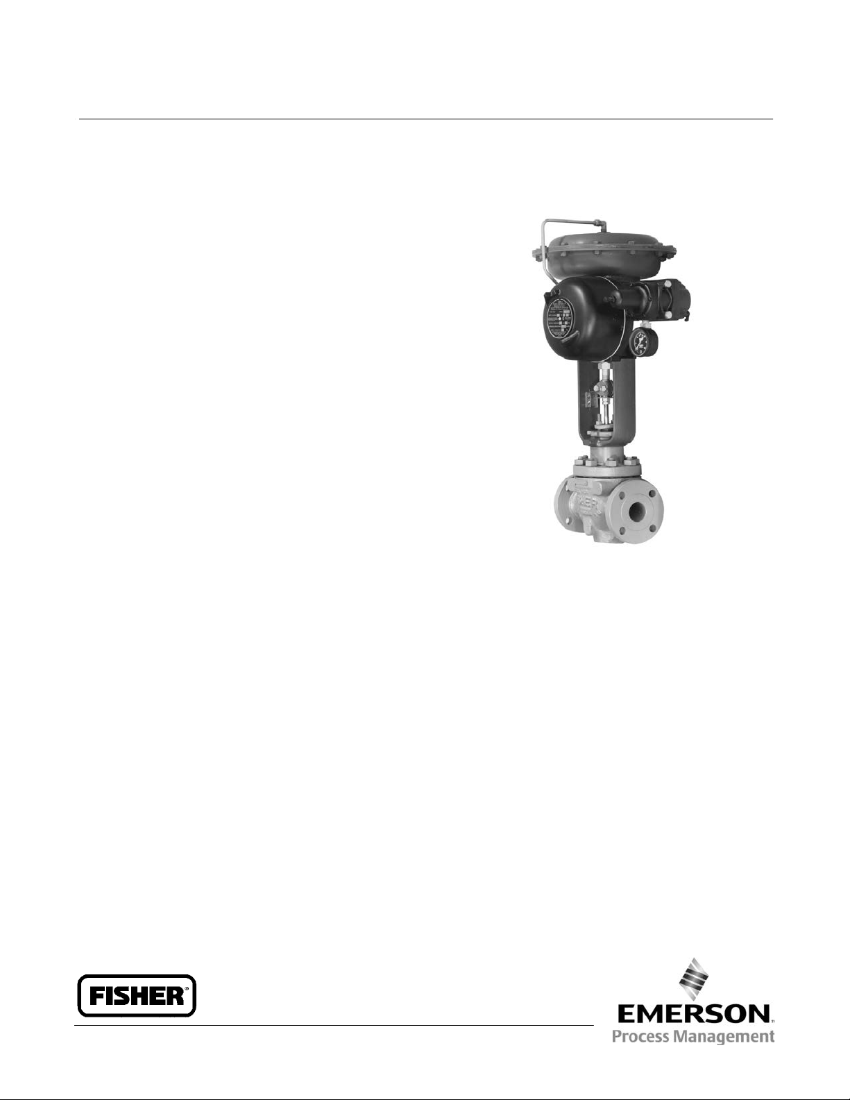
Fisherr 546NS Electro‐Pneumatic Transducer
The Fisher 546NS transducer receives a direct‐current
input signal and use a torque motor, nozzle‐flapper,
and pneumatic relay to convert the signal to a
proportional pneumatic output signal. Nozzle
pressure, which operates the relay, is also piped to the
torque motor feedback bellows. This provides a
comparison between input signal and nozzle pressure
and reduces errors in nozzle pressure.
The transducer can be mounted on a pneumatic
diaphragm control valve actuator to provide accurate
operation of the valve. The integrated high‐capacity
pneumatic relay eliminates the need for additional
boosters or relays for operation of control valves.
The transducer also can be used to provide stable
operation when its output signal is transmitted to
small terminal volume chambers such as control
bellows in pneumatic valve positioners.
Features
n Vibration Resistance—High natural frequency of
torque motor moving parts results in negligible
vibration influence. Meets typical seismic
requirements for nuclear service.
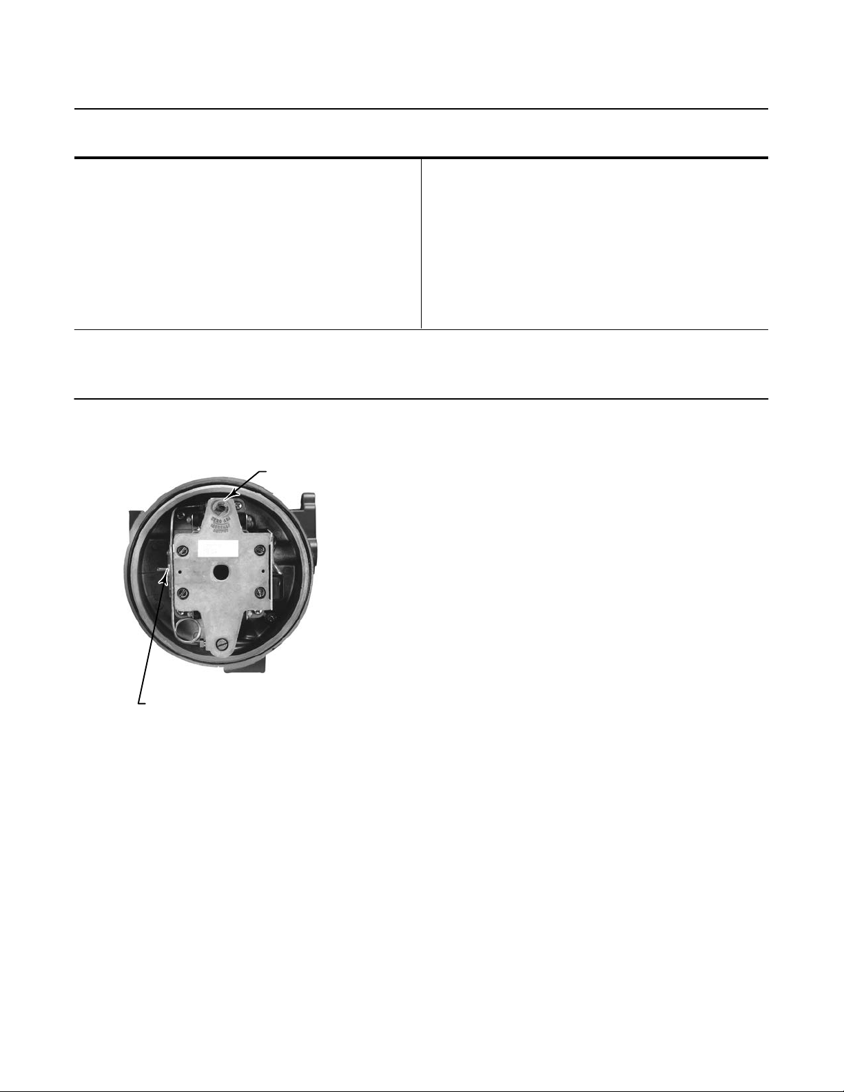
n Easy Adjustment—Screwdriver adjustments for span
and zero are conveniently located and have arrows
indicating rotation to increase settings (as shown in
figure 1).
Fisher 546NS Transducer Mounted on
657 Pneumatic Diaphragm Actuator
W2115
n Field‐Reversible Action—No additional parts
required to reverse action.
n Simple Relay Removal—Integrated pneumatic relay
is mounted outside case and can be removed
without disturbing electrical or pressure
connections or impairing explosion safety.
www.Fisher.com
Page 2

Product Bulletin
62.1:546NS
April 2015
Specifications
Available Configuration
Electro‐pneumatic signal transducer with
explosion‐proof case and cover, with EPDM
elastomers for use in elevated temperature and
radiation environments
The 546NS can be ordered
Fisher 67CFR filter regulator. The 51 mm (2 inch)
supply pressure gauge mounted on the regulator may
be
J 0 to 30 psig or J 0 to 60 psig range
Input Signals
J 4 to 20 mA DC, J 10 to 50 mA DC, or J two‐way
split range using either half of one of the standard
input signal spans
Internal Resistance of Torque Motor
4 to 20 mA DC Input Signal: 176 ±10 ohms
10 to 50 mA DC Input Signal: 90 ±10 ohms
J with or J without a
546NS Transducer
D103603X012
Performance
Actuator Loading Time: see figure 3
Reference Accuracy
Independent Linearity: ±0.50% of output signal span
Open Loop Gain: 26
Frequency Response: Gain is attenuated 3 dB at 20 Hz
with transducer output signal piped to a typical
instrument bellows with 305 mm (12 inch) of 1/4 inch
tubing
Electromagnetic Interference (EMI): Tested per IEC
61326‐1 (Edition 1.1). Meets emission levels for Class
A equipment (industrial locations) and Class B
equipment (domestic locations). Meets immunity
requirements for industrial locations (Table A.1 in the
IEC specification document). Immunity performance
shown in table 1.
Operative Ambient Temperature Limits
-40 to 66_C (-40 to 150_F)
(4)
(5)
: ±0.75% of output signal span
(1)
Output Signals
Ranges:
J 0.2 to 1.0 bar (3 to 15 psig), J 0.4 to 2.0 bar
(6 to 30 psig)
Action: Field reversible between
J reverse
Supply Pressure
(1)
J direct and
Recommended: 0.3 bar (5 psi) higher than upper
range limit of output signal
Maximum: 3.5 bar (50 psig)
Average Steady‐State Air Consumption
(2)(3)
0.44 m3/hr (16.5 scfh) at 1.4 bar (20 psi) supply
pressure
Maximum Output Air Capacity
At 1.4 bar (20 psig) Supply Pressure:
3
12.9 m
At 2.4 bar (35 psig) Supply Pressure:
18.5 m
/hr (480 scfh)
3
/hr (690 scfh)
(2)
Electrical Classification
Hazardous Area:
CSA—Explosion‐proof, Dust Ignition-proof, Div 2
FM—Explosion‐proof, Dust Ignition‐proof,
Non‐incendive
Refer to tables 2 and 3 for specific approval
information
NEMA 3R, CSA Enclosure 3
NEMA 3R mounting orientation requires vent location
to be below horizontal.
Adjustments
Zero and Span Adjustments: Screwdriver adjustments
located inside case (see figure 1)
Connections
Supply Pressure: 1/4 NPT internal located on side of
case (located on filter‐regulator if a 67CFR is mounted
to transducer)
Output Pressure: 1/4 NPT internal located on side of
case
Vent: 1/4 NPT internal with screen located on relay
Electrical: 1/2 NPT internal located on bottom of case
-continued-
2
Page 3
Product Bulletin
546NS Transducer
D103603X012
62.1:546NS
April 2015
Specifications (continued)
Construction Materials
Case and Cover: Aluminum
O‐Rings: EPDM
Flame Arrestors: Stainless steel
Supporting Bracket/Torsion Member: Stainless steel
Magnets: Alloy steel
Nozzle: Stainless steel
Feedback Bellows: Brass
Relay Body: Aluminum
Relay Restriction: Aluminum/Stainless steel
NOTE: Specialized instrument terms are defined in ANSI/ISA Standard 51.1 - Process Instrument Terminology.
1. The pressure/temperature limits in this document and any applicable standard or code limitation should not be exceeded.
2. Normal m
3. Average flow rate determined at 12 mA and 0.6 bar (9 psig) output.
4. Performance values are obtained using a 546 transducer with a 4 to 20 mA DC input signal and a 0.2 to 1.0 bar (3 to 15 psig) or a 0.4 to 2.0 bar (6 to 30 psig) output signal. Ambient temperature
is 24_C (75_F). A transducer with other input or output signals may exceed these values.
5. Reference accuracy includes the effects of non-linearity, hysteresis, and deadband per SAMA Standard PMC 20.1-1973.
3
/hr-‐Normal cubic meters per hour (0_C and 1.01325 bar, absolute). Scfh‐‐Standard cubic feet per hour (60_F and 14.7 psia).
Relay Diaphragm: EPDM/Nomex
Relay Valve Plug and Seat Ring: Brass
Mounting
Mounting parts are available for
actuator mounting,
mounting, or
J pipestand (2 inch nominal)
J surface mounting
Approximate Weight
4.1 kg (9 lb)
R
.
J control valve
Figure 1. Zero and Span Adjustments (Cover
Removed)
W5391
SPAN ADJUSTMENT
ZERO ADJUSTMENT
Principle of Operation
Refer to figure 2, and assume that the transducer is
direct acting. As the DC milliamp signal increases, so
does the magnetic field around the coils. This results in
an increased magnetic attraction between the
armature and the pole pieces. The armature rotates
slightly clockwise to cover the nozzle, increasing
pressure in the nozzle, the upper chamber of the relay,
and the feedback bellows. Increased nozzle pressure
and increased pressure in the upper chamber of the
relay cause the relay supply port to open, increasing
the output pressure to the actuator and the control
valve. At the same time, the increased pressure in the
feedback bellows acts to move the armature back to
the equilibrium position. In this way, the new nozzle
pressure is compared to the DC input signal by the
force balance principle.
As the DC input signal decreases, magnetic attraction
is reduced and the armature rotates slightly in the
counterclockwise direction to uncover the nozzle.
Decreased nozzle pressure and decreased pressure in
the upper chamber of the relay cause the relay exhaust
port to open and allow output pressure to bleed to
atmosphere. Pressure to the control valve is reduced
until equilibrium is attained.
Reverse‐acting transducers operate in a similar
manner except that when the DC input signal
increases, pressure to the actuator and control valve
decreases.
3
Page 4

Product Bulletin
62.1:546NS
April 2015
Figure 2. Transducer Schematic
FEEDBACK
BELLOWS
546NS Transducer
D103603X012
SPAN ADJUSTMENT
(MAGNETIC SHUNT)
ZERO ADJUSTMENT
PERMANENT MAGNET
POLE PIECES
COIL
ARMATURE
TORSION ROD
EXHAUST
OUTPUT PRESSURE
NOZZLE PRESSURE
SUPPLY PRESSURE
EXHAUST PRESSURE
CP4285-A
A1505-3
OUTPUT
RELAY
VALVE PLUG
Valve Stroking Time
Figure 3 shows relative times for loading and
exhausting an actuator. Exhausting times are
nominally 25 percent of the loading times. Stroking
time depends upon the size of the actuator,travel,
relay characteristics and the magnitude and rate of
change of the input signal. If stroking time is critical,
contact your Emerson Process Management
sales office.
ARMATURE
NOZZLE
CENTER SPACER ASSEMBLY
FIXED RESTRICTION
SUPPLY
Figure 3. Output‐Time Relationships
100
90
80
70
60
50
OUTPUT
40
30
20
(% OF 546NS OUTPUT SPAN)
10
0
0 102030405060708090100
19A1361‐A
A3103
LOADING
EXHAUSTING
TIME (%)
4
Page 5

546NS Transducer
D103603X012
Product Bulletin
62.1:546NS
April 2015
Nuclear‐Service
Applications
The 546NS transducer is designed for nuclear power
applications. The 546NS construction includes
materials that provide superior performance in
elevated temperature and radiation environments.
The O‐rings are EPDM (ethylene propylene) and the
diaphragms are EPDM/Nomex. EPDM demonstrates
superior temperature capability and shelf life over
nitrile. (Use a clean, dry, oil‐free air supply with
instruments containing EPDM components. EPDM is
subject to degradation when exposed to
petroleum‐based lubricants.) The Nomex diaphragm
fabric demonstrates improved strength retention at
elevated temperature and radiation conditions.
Under the 10CFR50, Appendix B, quality assurance
program, the 546NS transducer is qualified
“commercial grade dedicated”. These can be supplied
as 10CFR, Part 21 items.
Qualification
The 546NS is qualified to meet stringent
environmental conditions encountered in nuclear
power plant containment areas. Samples were
subjected to the tests summarized below:
n Thermal Aging: accelerated service temperature of
54_C (130_F) over 10 years.
n Radiation Aging: 6 MRads Total Integrated Dose
(TID)
n Seismic Event Simulation (DBE): no natural
frequencies found between 5‐100 Hz and seismic
dwells of 8g uniaxial from 3‐40 Hz.
n LOCA/MSLB Event Simulation: saturated steam for
14 hours at 160_C ( 320_F) followed by a gradual
reduction to 83_C (182_F) over a 10 hour period.
Upon conclusion of the above tests, no loss of function
or extreme degradation was found.
Installation
Standard positions for actuator mounting and
pipestand mounting are shown on the front cover
and figure 4, respectively. Dimensions are shown in
figure 4.
Ordering Information
To determine what ordering information is required,
refer to the Specifications table. Carefully review the
information under each specification and in the
referenced table. Specify the desired choice wherever
there is a selection to be made. Always specify the type
number as identified in the Available Configurations
specification.
For transducers that are to be used in intrinsically safe
installations, specify the rating required and the
system with which the unit will be used.
When ordering actuator mounting parts, specify the
actuator type, size, travel, and diaphragm pressure
range. For all Fisher 657 and 667 actuators except size
80, specify whether actuator yoke or actuator casing
mounting is desired (yoke mounting is only available
on size 80 actuators).
For split‐range operation, specify the portion of input
signal to be used; e.g. 4 to 12 milliamps of a standard
4 to 20 milliamp signal.
For nuclear service applications, consult your Emerson
Process Management sales office for additional
information and order assistance.
5
Page 6

Product Bulletin
62.1:546NS
April 2015
Figure 4. Dimensions
546NS Transducer
D103603X012
1/4 NPT
OUTPUT
CONNECTION
51
(2.00)
CP7280-E
A1249-1
51
(2.00)
40
(1.56)
44
(1.75)
78
(3.06)
51 PIPE
(2.00)
(12.94)
(0.88)
70
(2.75)
329
22
125
(4.94)
32
(1.25)
83
(3.25)
1/2 NPT CONDUIT
CONNECTION
PIPESTAND MOUNTING
46
(1.81)
1/4 NPT SUPPLY
CONNECTION
WHEN FILTER
REGULATOR
IS FURNISHED
(2.62)
164
(6.44)
165
(6.50)
1/4 NPT SUPPLY
CONNECTION
WHEN FILTER
REGULATOR
IS NOT FURNISHED
171
(6.75)
52
(2.06)
43
(1.69)
67
37
(1.44)
6.3
(0.25)
40
(1.56)
1/4 NPT OUTPUT
CONNECTION
51
(2.00)
16
(0.62)
CP6477-E
A1248-1
40
(1.56)
44
(1.75)
(2.25)
(2.75)
70
56
329
(12.94)
78
(3.06)
8.7
(0.34)
37
(1.44)
70
(2.75)
ACTUATOR MOUNTING
125
(4.94)
32
(1.25)
(3.25)
22
(0.88)
46
(1.81)
83
164
(6.44)
1/2 NPT CONDUIT
CONNECTION
mm
(INCH)
6
Page 7

546NS Transducer
D103603X012
Product Bulletin
62.1:546NS
April 2015
Table 1. Electromagnetic Immunity Performance
Port Phenomenon Basic Standard Test Level Performance Criteria
Electrostatic discharge (ESD) IEC 61000‐4‐2
Enclosure
I/O signal/control
Specification limit = ±1% of span
1. A=No degradation during testing. B = Temporary degradation during testing, but is self‐recovering.
Radiated EM field IEC 61000‐4‐3
Rated power frequency magnetic field IEC 61000‐4‐8 60 A/m at 50 Hz A
Burst (fast transients) IEC 61000‐4‐4 1 kV A
Surge IEC 61000‐4‐5 1 kV (line to ground only, each) B
Conducted RF IEC 61000‐4‐6
4 kV contact
8 kV air
80 to 1000 MHz @ 10V/m with
1 kHz AM at 80%
150 kHz to 80 MHz at 3 Vrms
with 1kHz AM at 80%
Table 2. Hazardous Area Classifications—CSA (Canada)
Certification Body Certification Obtained Temperature Code
CSA
Explosion-proof
Class I, Division 1, Group C,D
Class II, Division 1, Groups E,F,G
Class I, Division 2, Groups A,B,C,D
Class II, Division 2, Groups F,G
T5 (Tamb = 66_C)
Table 3. Hazardous Area Classifications—FM (United States)
Certification Body Certification Obtained Temperature Code
FM
Explosion-proof
Class I, Division 1, Groups C,D
Class II, Division 1, Groups E,F,G
Class I, Division 2, Groups A,B,C,D
Class II, Division 2, Groups F,G
T5 (Tamb = 60_C)
(1)
A
A
A
T5
T5
7
Page 8

Product Bulletin
62.1:546NS
April 2015
546NS Transducer
D103603X012
Neither Emerson, Emerson Process Management, nor any of their affiliated entities assumes responsibility for the selection, use or maintenance
of any product. Responsibility for proper selection, use, and maintenance of any product remains solely with the purchaser and end user.
Fisher is a mark owned by one of the companies in the Emerson Process Management business unit of Emerson Electric Co. Emerson Process Management,
Emerson, and the Emerson logo are trademarks and service marks of Emerson Electric Co. All other marks are the property of their respective owners.
The contents of this publication are presented for informational purposes only, and while every effort has been made to ensure their accuracy, they are not
to be construed as warranties or guarantees, express or implied, regarding the products or services described herein or their use or applicability. All sales are
governed by our terms and conditions, which are available upon request. We reserve the right to modify or improve the designs or specifications of such
products at any time without notice.
Emerson Process Management
Marshalltown, Iowa 50158 USA
Sorocaba, 18087 Brazil
Chatham, Kent ME4 4QZ UK
Dubai, United Arab Emirates
Singapore 128461 Singapore
www.Fisher.com
E 2012, 2015 Fisher Controls International LLC. All rights reserved.
8
 Loading...