

Page 1
377 Trip Valve
D200318X012
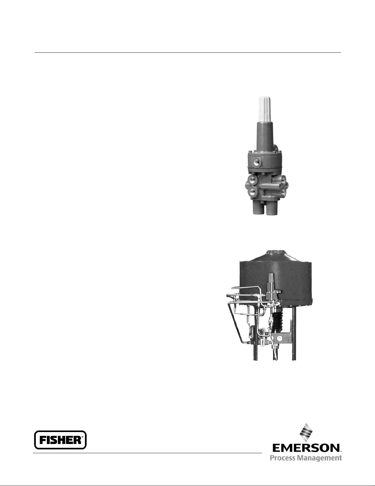
Fisherr 377 Trip Valve
Fisher 377 pressure‐sensing trip valves are for control
applications where a specific valve/actuator action is
required when supply pressure falls below a specific
point. When supply pressure falls below the trip point
(see figure 1), the trip valve causes the actuator to fail
up, lock in the last position, or fail down. When the
supply pressure rises above the trip point, the 377 trip
valve automatically resets, allowing the system to
return to normal operation. The trip valve can be
top‐mounted on a manifold, yoke‐mounted, or
bracket‐mounted to match the application
requirements. 377 trip valves can be used with Fisher
480, 585C, 685, 1061, 1066, 1069, and Bettist G
Series piston actuators.
Product Bulletin
62.3:377
July 2014
Features
n Cost Effective—Single trip valve construction
reduces costs and spare part requirements of those
systems using three separate switching valves to
perform the failure functions. A single trip valve
greatly simplifies piping requirements.
n Ease of Mode Conversion—Conversion to any of the
fail modes requires only minor hookup changes.
n Adjustable Trip Valve—The trip point is adjustable
for specific supply pressure requirements.
n Reliable Operation—The trip valve design includes
large diaphragm areas and few moving parts for
efficient performance, minimum maintenance, and
long service life.
W4292‐1
W8435‐1
Fisher 377 Trip Valve Mounted on
Size 130 585C Actuator
www.Fisher.com
Page 2
Product Bulletin
62.3:377
July 2014
Specifications
Available Configurations
When supply pressure falls below the trip point,
377D Trip Valve: Fails actuator piston down. Includes
check valve and volume tank.
377L Trip Valve: Locks actuator piston in the last
position.
377U Trip Valve: Fails actuator piston up. Includes
check valve and volume tank.
377CW Trip Valve: Fails fully clockwise to close the
valve. Requires check valve and volume tank. Trip
valve moves piston to either up/down position and
requires actuator configuration for actual clockwise
movement.
377CCW Trip Valve: Fails fully counterclockwise to
close the valve. Requires check valve and volume
tank. Trip valve moves piston to either up/down
position and requires actuator configuration for
actual counterclockwise movement.
All 377 trip valves can be converted to any of the
above fail modes with minor hookup changes
Allowable Supply Pressure for Trip Valve
Maximum: 10.3 bar (150 psig)
Minimum: 3.8 bar (55 psig)
Outlet Pressure
(1)
Normal Operation: Pressure from control device
Fail‐Up or Fail‐Down Mode: Maximum volume tank
pressure
Lock‐In‐Last‐Position: Respective cylinder pressure
(1)
377 Trip Valve
D200318X012
Flow Coefficients (C
Depends on flow path (shown in figure 3) as follows:
Port A to Port B and Port D to Port E: 0.5
Port B to Port C and Port E to Port F: 0.6
Body Connections
1/4 NPT internal
Temperature Capabilities
Nitrile Diaphragms and O‐Rings: -40 to 82°C
(-40 to 180°F)
Fluorocarbon Diaphragms and O‐Rings: -18 to 104°C
(0 to 220°F)
Volume Tank Maximum Internal Working Pressure
(for 377D, 377U, 377CW and 377CCW trip valves)
Standard: 10.3 bar (150 psig) for non‐ASME approved
applications
(4)
ASME Approved Applications: Rated 10.3 bar (150
psig), maximum; 9.3 bar (135 psig), recommended
Volume Tank Sizing
See sizing section
Hazardous Area Classification
Complies with the requirements of ATEX Group II
Category 2 Gas and Dust
(3)
)
v
(1)
Trip Point
(2)
Adjustable from a minimum of 2.8 bar (40 psig) to a
maximum of 72 percent of supply pressure;
see figure 1
Reset: 12.5 to 33 percent above adjusted trip point
Table of Contents
Features 1.....................................
Safety Certification 3............................
Principle of Operation 4.........................
377D Trip Valve 4.............................
377L Trip Valve 6..............................
377U Trip Valve 7.............................
377CW and 377 CCW Trip Valves 7...............
2
377 SST
Safety Instrumented System Classification
SIL 3 capable - certified by exida Consulting LLC
-Continued-
Volume Tank Sizing 8...........................
Installation 9..................................
Ordering Information 10.........................
Application 10................................
Trip Valve 10.................................
Page 3
377 Trip Valve
D200318X012
Specifications (continued)
Product Bulletin
62.3:377
July 2014
Mounting
Top‐Mounted: Manifold‐mounted between a 3570
positioner and a 480 actuator (manifolds cannot be
Mounting Manifold: 0.5 kg (1.2 pounds)
Volume Tank: Varies between 5.4 and 363 kg (12 and
800 pounds) depending on size
supplied with 585C, 685, 1061, 1066, and 1069
piston actuators)
Side‐Mounted: Yoke‐mounted or bracket‐mounted
Construction Materials
for use with a FIELDVUEt DVC6200, DVC6200f,
DVC6200p, DVC6000, or DVC6000f digital valve
controller
Housing:
J Aluminum or J Stainless steel
Cover: 25% mineral‐filled thermoplastic polyester
O‐Rings: Nitrile or fluorocarbon
Approximate Weight
Trip Valve
Aluminum: 0.95 kg (2.1 pounds)
Stainless Steel: 2.31 kg (5.1 pounds)
1. The pressure/temperature limits in this document and any applicable standard or code limitation should not be exceeded.
2. If the trip point is not specified, the trip point is factory‐set at 72 percent of supply pressure or 2.8 bar (40 psig), whichever is higher.
3. Values represent nominal C
4. This tank is rated at 14.5 bar (240 psig) in LP service. When used with air, the rating should be considered to be 10.3 bar (150 psig), consistent with the maximum
pressure allowed for the 377 trip valve.
measures for each port pair using a trip valve/actuator combination.
v
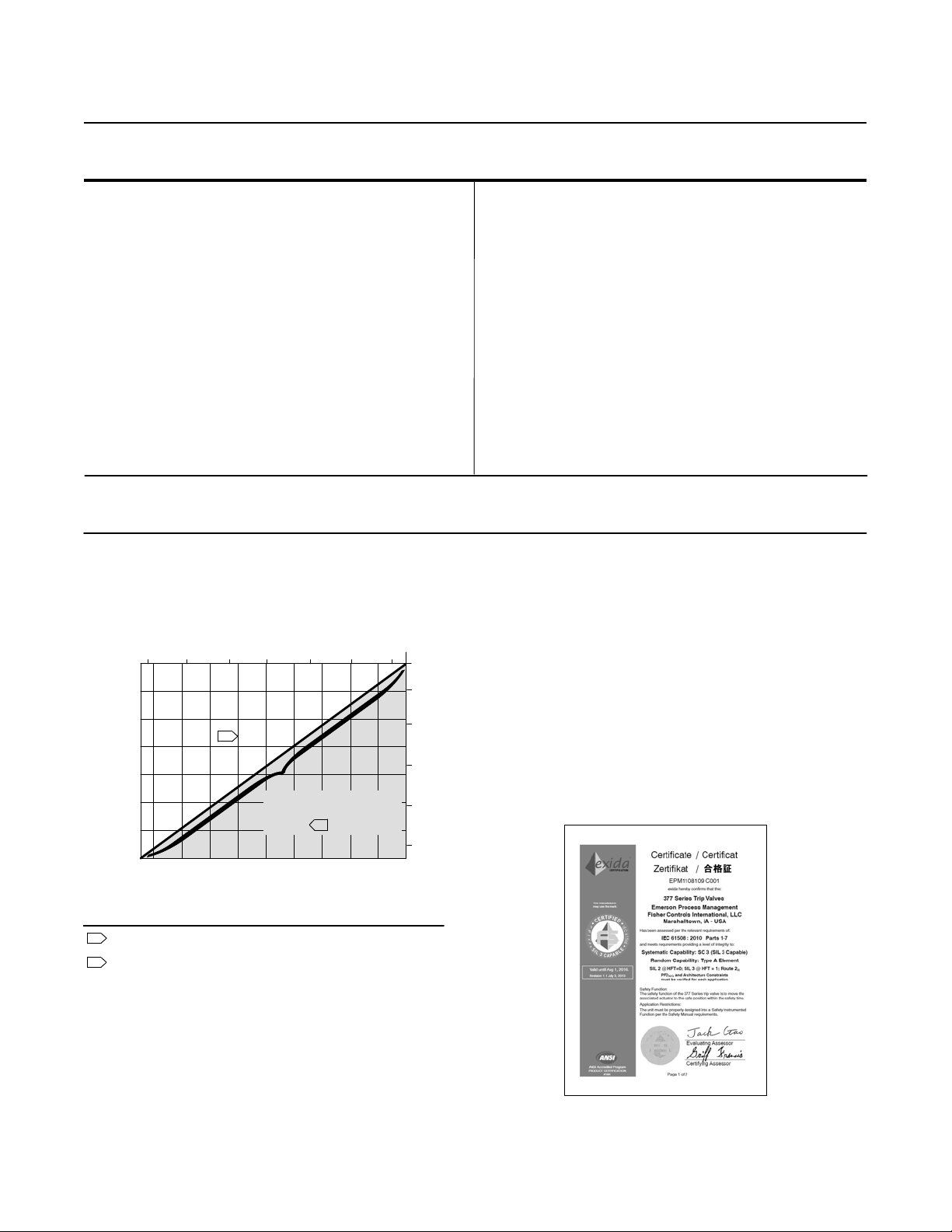
Figure 1. Maximum Trip Point Settings
Diaphragms: Nitrile or fluorocarbon
Interior parts
Aluminum construction: Brass, aluminum, steel, and
stainless steel
Stainless Steel construction: Stainless steel
Safety Certification
The 377 SST is certified for use in Safety Instrumented
45 67 8 910
110
100
90
80
70
TRIP POINT, PSIG
60
50
40
A2779‐2
SUPPLY PRESSURE, BAR
2
MAXIMUM TRIP POINT
SETTING TO ENSURE
RESET
SUPPLY PRESSURE, PSIG
10.3
7.6
7
6
5
TRIP POINT, BAR
4
1
3
1501401301201101009080706055
System (SIS) applications. Certification is by exida
Consulting LLC, a global provider of functional safety
and control system security (see figure 2). SIS
certification is identified on the product by a label
affixed to the pilot body.
The functional safety assessment was performed to
the requirements of IEC 61508: ed2, 2010, SIL3 for
mechanical components.
Figure 2. exida Certificate
1 Trip point may be set to any value between 2.8 bar (40 psig) and the
maximum trip point line.
2 Reset occurs a 12.5 to 33 percent above adjusted trip point.
3
Page 4
Product Bulletin
62.3:377
July 2014
377 Trip Valve
D200318X012
Principle of Operation
377D Trip Valve
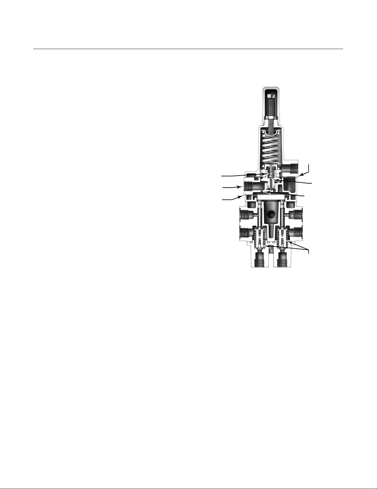
In normal operation, supply pressure loads the upper
diaphragm (see figure 3) of the unit. The valve plug
spring keeps the exhaust port closed. Supply pressure
also loads the lower diaphragm through the
restriction, causing the plug assemblies to move down
and isolate ports C and F while connecting port A to B
and port D to E.
Normal actuator control pressure flows from the
control device to the top of the cylinder through ports
A and B and to the bottom of the cylinder through
ports D and E. A volume tank is charged to maximum
supply pressure through a check valve in order to
retain maximum supply pressure in the volume tank if
supply pressure drops.
Figure 3. Simplified Sectional View of Trip Valve
UPPER
DIAPHRAGM
VALVE
PLUG SPRING
SUPPLY
CONNECTION
LOWER
DIAPHRAGM
PORT D
PORT E
EXHAUST
PORT
RESTRICTION
PORT A
PORT B
When supply pressure falls below the trip point
pressure in the fail‐down mode (see figure 4), the
exhaust port opens, venting the supply pressure that is
loading the lower diaphragm. This causes the upper
ports of the plug assemblies to close and shut off
normal pressure flow from the control device to the
actuator.
Volume tank pressure then flows through ports C and
B to the top of the actuator cylinder, while pressure in
the bottom of the actuator cylinder is vented through
ports E and F. The pressure imbalance created forces
the actuator piston down.
PLUG
ASSEMBLIES
W4303‐1
PORT F PORT C
When supply pressure is restored, it loads the upper
and lower diaphragms, causing the trip valve to reset.
The exhaust port closes. The upper ports of the plug
assemblies open, and the lower ports close. Normal
actuator control pressure flow from the control device
is restored through ports A and B and ports D and E.
The check valve opens and recharges the volume tank
to the maximum supply pressure.
4
Page 5

377 Trip Valve
D200318X012
Figure 4. Fisher 377D Trip Valve Shown Tripped
MAIN SPRING
SPRING
VALVE PLUG
UPPER
DIAPHRAGM
EXHAUST
PORT
SUPPLY
PRESSURE
LOWER
DIAPHRAGM
PORT D
PORT E
LOWER
PORTS
PORT F
PORT C
VENT
PORT A
PORT B
UPPER PORTS
PLUG
ASSEMBLIES
Product Bulletin
62.3:377
July 2014
ACTUATOR
CONTROL
DEVICE
DVC6200
CHECK
VALVE
VOLUME
TANK
GE08412-A
A6905-1
SUPPLY PRESSURE
CONTROL PRESSURE TO TOP OF
CYLINDER (BLOCKED)
CONTROL PRESSURE TO BOTTOM
OF CYLINDER (BLOCKED)
PRESSURE TO TOP OF CYLINDER
(FROM VOLUME TANK)
PRESSURE FROM BOTTOM OF CYLINDER
(VENTING)
LOWER DIAPHRAGM LOADING PRESSURE
(BEING VENTED)
5
Page 6

Product Bulletin
62.3:377
July 2014
Figure 5. Fisher 377L Trip Valve Shown Tripped
377 Trip Valve
D200318X012
MAIN SPRING
GE08414-A
A6906-1
SPRING
VALVE PLUG
UPPER
DIAPHRAGM
EXHAUST
PORT
SUPPLY
PRESSURE
LOWER
DIAPHRAGM
PORT D
PORT E
LOWER
PORTS
PORT F
VENT
PORT A
PORT B
UPPER
PORTS
PLUG
PORT C
SUPPLY PRESSURE
CONTROL PRESSURE TO TOP OF
CYLINDER (BLOCKED)
CONTROL PRESSURE TO BOTTOM
OF CYLINDER (BLOCKED)
ASSEMBLIES
ACTUATOR
DVC6200
CONTROL
DEVICE
PRESSURE TO TOP OF CYLINDER
(STATIC)
PRESSURE FROM BOTTOM OF CYLINDER
(STATIC)
LOWER DIAPHRAGM LOADING PRESSURE
(BEING VENTED)
377L Trip Valve
When supply pressure falls below the trip point in the
lock‐in‐last‐position mode (see figure 5), the exhaust
port opens, venting supply pressure from the lower
diaphragm. This causes the upper ports of the plug
assemblies to close and the lower ports to open. Since
ports C and F are plugged, no pressure change occurs
6
on either side of the actuator piston, and the piston is
pressure‐locked in position upon loss of supply
pressure. No volume tank is necessary in this mode.
When supply pressure is restored, the plug assemblies
move back into the normal operating position, and
supply pressure flows from the control device through
ports A and B to the actuator.
Page 7

377 Trip Valve
D200318X012
Figure 6. Fisher 377U Trip Valve Shown Tripped
Product Bulletin
62.3:377
July 2014
MAIN SPRING
GE08413-A
A2284-6
SPRING
VALVE PLUG
UPPER
DIAPHRAGM
EXHAUST
PORT
SUPPLY
PRESSURE
LOWER
DIAPHRAGM
PORT D
PORT E
LOWER
PORTS
PORT F
PORT C
VENT
PORT A
PORT B
UPPER PORTS
PLUG
ASSEMBLIES
SUPPLY PRESSURE
CONTROL PRESSURE TO TOP OF
CYLINDER (BLOCKED)
CONTROL PRESSURE TO BOTTOM
OF CYLINDER (BLOCKED)
ACTUATOR
CONTROL
DEVICE
DVC6200
CHECK
VALVE
VOLUME
TANK
PRESSURE TO TOP OF CYLINDER
(VENTING)
PRESSURE FROM BOTTOM OF CYLINDER
(FROM VOLUME TANK)
LOWER DIAPHRAGM LOADING PRESSURE
(BEING VENTED)
377U Trip Valve
The fail‐up mode of operation (figure 6) is similar to
the fail‐down mode of operation except that
connections to port C and F are reversed. When supply
pressure falls below the trip point, the top of the
actuator cylinder vents, and volume tank pressure
loads the bottom of the actuator cylinder. The
pressure imbalance created forces the actuator piston
up.
377CW and 377CCW Trip Valves
Makes use of the 377D or 377U trip valve
configurations, a piston actuator, and volume tank
with check valve to move the piston actuator to either
the up or down position. Requires the actuator and
valve configuration for actual clockwise or
counterclockwise movement.
7
Page 8

Product Bulletin
62.3:377
July 2014
377 Trip Valve
D200318X012
Volume Tank Sizing
Note
State and local regulations may require the use of
ASME‐approved volume tanks. It is the user's responsibility
to determine requirements and applicable regulations for
proper volume tank selection.
Several different tanks of varying capacities are
available. The volume tank must be selected so that its
pressure at any time is greater than the minimum
percentage of maximum supply pressure required to
stroke the actuator (see figure 7).
Figure 7. Volume Tank Sizing Graph
1. Size the volume tank as indicated below:
For Actuators on Sliding Stem
Valves, Determine:
Y = F/AP x 100 Y = P
For Actuators on Rotary‐Shaft
Valves, Determine:
/P x 100
r
Where:
Y = Minimum failure positioning percentage
F = Actuator thrust required in normal operation to
position the valve at the desired limit of travel
A = Effective piston area (from the appropriate
actuator bulletin)
P = Maximum supply pressure available
P
= Highest pressure required by the actuator to
r
stroke the valve (from the appropriate actuator
sizing technique)
2. With the minimum failure positioning percentage
obtained in step 1, enter the value on the abscissa
of the graph in figure 7. Locate the corresponding
point on the curve, and read across to find the
volume ratio, R.
3. Determine:
VOLUME RATIO, R
A2281‐1
MINIMUM FAILURE POSITIONING
PERCENTAGE, Y
V
= (XA)/R
T
Where:
X = Maximum actuator travel from the appropriate
actuator bulletin. For rotary actuators, substitute
total displacement (XA). Actuator displacement can
be found in the product bulletin, or contact your
Emerson Process Management sales office.
V
= Minimum volume tank size required
T
R = Volume ratio from step 2
8
Page 9

377 Trip Valve
D200318X012
Product Bulletin
62.3:377
July 2014
Installation
The 377 trip valve may be mounted in any position
without affecting normal operation. Dimensions are
shown in figure 8 and tables 1 and 2.
Table 1. Standard Volume Tank Dimensions
Tank Volume J L
Liters Inch3/Gal mm Inches mm Inches
11.8 721/3.1 309 12.16 318 12.5
21.6 1315/5.7 310 12.19 451 17.75
32.3 1970/8.5 309 12.16 595 23.43
42.9 2615/11.3 309 12.16 737 29.00
65.6 4001/17.3 309 12.16 1095 43.12
131.1 8002/34.6
Requires two 65.6 liter (4001 inch3/
17.3 gal) volume tanks
Table 2. ASME‐Approved, Canadian Registered
Volume Tank Dimensions
Tank Volume J L
Liters Inch3/Gal mm Inches mm Inches
8.5 518/2.2 208 8.19 337 13.25
24.9 1520/6.6 305 12 427 16.81
30 1831/7.9 254 10 684 26.94
42.8 2609/11.3 305 12 681 26.81
68.8 4199/18.1 360 14.19 792 31.19
71.6 4371/18.9 305 12 1087 42.81
143.3 8742/37.86
114 6930/30 406 16 965 38
227 13860/60 508 20 1219 48
303 18480/80 610 24 1600 63
454 27720/120 610 24 1702 67
908 55440/240 762 30 2134 87
Figure 8. Dimensions of Trip Valve with Manifold (also see tables 1 and 2)
57
(2.25)
CAP
REMOVAL
CLEARANCE
1/4 18 NPT
SUPPLY CONNECTION
154
(6.06)
PORT D
100
(3.94)
46
(1.81)
PORT C
PORT F
PORT E
141
(5.56)
Requires two 71.6 liter (4371 inch3/
L
J
STANDARD
TANK
18.9 gal volume tanks
ASME‐APPROVED
1
L
TANK
J
1
AF4605‐K
19A7995‐A
A2778‐4
1 Refer to table 1 and 2 for J and L dimensions
76
(3.00)
90
(3.56)
54
(2.12)
1/4 18 NPT
VENT CONNECTION
mm
(INCH)
9
Page 10

Product Bulletin
62.3:377
July 2014
377 Trip Valve
D200318X012
Ordering Information
When ordering specify:
Application
1. Available supply pressure
2. Actuator type number and size
3. Aluminum or stainless steel construction
4. Input signal range
5. Operating ambient temperature
6. Trip point (If the trip point is not specified, the unit
is factory‐set to trip at 72 percent of supply pressure
or 2.8 bar (40 psig), whichever is higher.)
7. Volume tank size
Trip Valve
Refer to the specifications. Review the information
under each specification and in the referenced figures.
Specify the desired choice wherever there is a selection
to be made. Be sure to specify the type number as
described in the Available Configurations specification.
Refer to table 3 for guidelines on specifying the correct
trip valve.
Table 3. Guidelines for Specifying Fisher 377 Trip
Valve
Actuator Type Fail Mode Valve Action
Fail Open
Sliding‐Stem
Fail Closed
Rotary:
1035
Bettis G Series
Rotary:
1069
1. PDTC—Push Down to Close; PDTO—Push Down to Open
Fully Clockwise
Fully
Counterclockwise
Fully Clockwise ‐ ‐ ‐ 377CW
Fully
Counterclockwise
Clockwise
(1)
Trip Valve
PDTC 377U
PDTO 377D
PDTC 377D
PDTO 377U
377CW
to Close
‐ ‐ ‐ 377CCW
377CCW
10
Page 11

377 Trip Valve
D200318X012
Product Bulletin
62.3:377
July 2014
11
Page 12

Product Bulletin
62.3:377
July 2014
377 Trip Valve
D200318X012
Neither Emerson, Emerson Process Management, nor any of their affiliated entities assumes responsibility for the selection, use or maintenance
of any product. Responsibility for proper selection, use, and maintenance of any product remains solely with the purchaser and end user.
Fisher and FIELDVUE are marks owned by one of the companies in the Emerson Process Management business unit of Emerson Electric Co. Emerson Process
Management, Emerson, and the Emerson logo are trademarks and service marks of Emerson Electric Co. All other marks are the property of their respective
owners.
The contents of this publication are presented for informational purposes only, and while every effort has been made to ensure their accuracy, they are not
to be construed as warranties or guarantees, express or implied, regarding the products or services described herein or their use or applicability. All sales are
governed by our terms and conditions, which are available upon request. We reserve the right to modify or improve the designs or specifications of such
products at any time without notice.
Emerson Process Management
Marshalltown, Iowa 50158 USA
Sorocaba, 18087 Brazil
Chatham, Kent ME4 4QZ UK
Dubai, United Arab Emirates
Singapore 128461 Singapore
www.Fisher.com
E 1985, 2014 Fisher Controls International LLC. All rights reserved.
12
 Loading...