


Emerson Fisher 249, Fisher 249P, Fisher 249VS, Fisher 249W, Fisher 2500 Data Sheet
...
Level Instruments |
Product Bulletin |
11.2:Level |
|
D103219X012 |
February 2015 |
|
|
Fisherr Level Instruments
W8418 1
FISHER L2 PNEUMATIC
LEVEL CONTROLLER
X0682
FISHER 2100E
ELECTRIC LEVEL SWITCH
W8678
X0660
FIELDVUE DLC3010 DIGITAL LEVEL
CONTROLLER IN COMBINATION WITH
A FISHER 249W SENSOR FISHER L2e ELECTRIC
LEVEL CONTROLLER
ν FIELDVUE™ Digital Level Instruments—
Microprocessor based, communicating digital level transmitter for liquid level, specific gravity (density), and liquid level interface. Using HARTR or FOUNDATION™ fieldbus communications protocol, the DLC3010/DLC3020f digital level controller gives easy access to information critical to process operation. Available in combination with a 249 sensor to meet mounting requirements.
ν Fisher 2100E electric switch and 2100 on-off pneumatic switch— Sense high or low liquid levels. Typically, these switches electrically or pneumatically operate safety shutdown systems for field processing equipment in oil and gas industry applications
ν Liquid Level Controllers— Displacer type sensors used to detect liquid level or interface of two liquids of different specific gravities. The L2e electric level controller, in conjunction with the Fisher easy-Drive™ actuator, can provide a fully electric level control loop; the L2 pneumatic level controller offers snap-acting, throttling control, while the on-off/direct acting L2sj controller features a low-bleed relay to help to conserve natural gas to reduce emissions.
ν Pneumatic Liquid Level Instruments— Proportional control mode. The 2500 controller/transmitter receives the change in fluid level or fluid to fluid interface level from the change in buoyant force the fluid exerts on the sensor displacer. Available in combination with a 249 sensor to meet mounting requirements.
www.Fisher.com
Product Bulletin |
Level Instruments |
11.2:Level |
|
February 2015 |
D103219X012 |
|
|
FIELDVUE Digital Level
Instruments
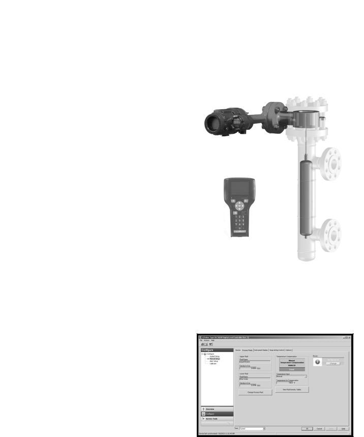
FIELDVUE DLC3010 digital level controllers (figures 1 and 3) are loop powered instruments. In conjunction with a 249 sensor, they measure changes in liquid level, the level of an interface between two liquids, or liquid specific gravity (density). The DLC3020f is a fieldbus powered instrument that measures liquid level or interface between two liquids. A level, density, or interface level change in the measured fluid causes a change in the displacer position.
This change is transferred to the torque tube assembly and to the digital level controller lever assembly. The rotary motion moves a magnet attached to the lever assembly, changing the magnetic field that is sensed by the Hall effect sensor. In the DLC3010, the sensor converts the magnetic field signal to a varying electronic signal, which is converted to a 4 20 mA output signal. In the DLC3020f, the sensor converts the changing magnetic field to a digital signal, which is ambient temperature compensated, linearized, and sent to the electronics assembly.
Standard or Custom Configuration... the DLC3010 digital level controller in combination with a 249W sensor enables users to install digital level transmitters to a variety of industry standard or custom process vessel connections. The sensor consists of a wafer body, torque tube assembly and displacer and is rated for CL150, 300, and 600. The wafer body mounts between NPS 3 or 4 raised face flanges. Custom configurations are also available to meet your specific application requirements. Refer to the DLC3010/DLC3020f specifications in tables 1, 2, 3, and 9, and the 249 specifications in tables 4, 5, 6, 7, 8, and 9 for product line capabilities and options.
HART/AMS Compliant... The DLC3010 uses HART protocol to interface with the Field Communicator (see figure 1) for field interface operations. Advanced user interface capabilities are enabled by AMS Suite: Intelligent Device Manager.
FOUNDATION fieldbus/AMS Compliant... The DLC3020f uses FOUNDATION fieldbus protocol to interface with the Field Communicator (see figure 1) for field interface operations. Advanced user interface capabilities are enabled by AMS Suite: Intelligent Device Manager (see figure 2).
Figure 1. Fisher DLC3010 Digital Level Controller in Combination with a 249W Sensor —Installed in a Typical Customer Supplied Cage
475 FIELD COMMUNICATOR
W8678
Figure 2. AMS Suite: Intelligent Device Manager
Configuration Screen
2
Level Instruments |
Product Bulletin |
11.2:Level |
|
D103219X012 |
February 2015 |
|
|
Simplified Setup and Calibration... With the electronic Device Setup, digital level controller startup is straightforward and fast. Level and temperature alarms, specific gravity tables, calibration trim, and trending are readily configurable. DLC3010/DLC3020f digital level controllers also support re ranging without a fluid reference.
Responsive to Small Process Change... Accurate, high gain analog to digital conversion enables measurement of small changes in the process variable. In addition, an input filter and output damping may be adjusted by the user to attenuate noise from mechanical disturbance or liquid turbulence at the displacer.
Easy Maintenance... Field wiring connections are in a compartment separated from the electronics. This helps to protect the electronics from any moisture brought into the housing by the field wiring. This also eases installation and maintenance. The digital level controller does not have to be removed to facilitate troubleshooting or service. However, if it is necessary to remove the digital level controller for in shop maintenance and calibration, field wiring does not need to be disconnected.
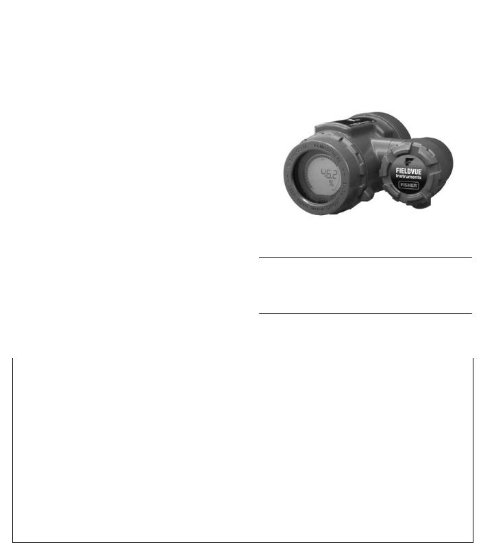
Figure 3. FIELDVUE DLC3020f Digital Level Controller
W6102 1
Note
Mountings for Masoneilan, Yamatake and Foxboro/Eckhardt sensors are available. Contact your Emerson Process Management sales office for mounting kit information.
Table 1. FIELDVUE DLC3010 General Specifications
Controller |
For use with 249 caged and |
DLC3010 |
|
Selections(1) |
uncaged displacer sensors |
||
|
|||
|
|
Level, Interface or Density: Rotary motion of the torque tube shaft proportional to changes in liquid lever, |
|
Input Signal |
|
interface level, or density that change the buoyancy of the displacer. |
|
|
Process Temperature: Interface for 2 or 3 wire 100 ohm platinum RTD for sensing process temperature, |
||
|
|
||
|
|
or optional user entered target temperature to permit compensating for changes in specific gravity |
|
Output Signal |
Analog |
4 20 mA DC direct (increasing input increases output) or reverse action |
|
Digital |
HART 1200 baud FSK (frequency shift keyed) |
||
|
|||
Supply |
|
12 30 VDC; the instrument has reverse polarity protection |
|
Ambient Relative Humidity |
0 to 95% non condensing |
||
Approximate Weight (Controller) |
2.7 kg (6 pounds) |
||
Option |
|
Heat insulator |
|
Electrical Housing |
NEMA 4X, CSA Enclosure, IP66 |
||
|
|
CSA—Intrinsically Safe, Explosion-proof, Division 2, Dust Ignition-proof |
|
|
|
|
|
Hazardous Area Classification(2) |
FM—Intrinsically Safe, Explosion-proof, Non-incendive, Dust Ignition-proof |
||
|
|||
ATEX—Intrinsically Safe, Type n, Flameproof |
|||
|
|
||
|
|
|
|
|
|
IECEx—Intrinsically Safe, Type n, Flameproof |
|
|
|
|
|
1. Also refer to tables 4, 5, 6, and 7.
2. Other Certifications/Classifications available. Contact your Emerson Process Management Sales office for additional information.
3

|
Product Bulletin |
|
|
|
|
Level Instruments |
|
||||
|
11.2:Level |
|
|
|
|
|
|
|
|||
|
February 2015 |
|
|
|
|
|
D103219X012 |
|
|||
|
|
|
|
|
|
|
|
|
|
|
|
|
Table 2. FIELDVUE DLC3020f General Specifications |
|
|
|
|
||||||
|
|
|
|
|
|
|
|
|
|
|
|
|
Controller |
|
For use with 249 caged and |
|
|
DLC3020f |
|
|
|||
|
Selections(1) |
|
uncaged displacer sensors |
|
|
|
|
||||
|
|
|
|
|
|
|
|
||||
|
|
|
|
|
|
Level Sensor Input: Rotary motion of the torque tube shaft proportional to buoyant force of the displacer |
|
||||
|
Device Inputs |
|
|
|
caused by changes in liquid level or interface level. |
|
|
|
|||
|
|
|
|
|
|
||||||
|
|
|
|
Process Temperature: Interface for 2 or 3 wire 100 ohm platinum RTD for sensing process temperature; |
|
||||||
|
|
|
|
|
|
AO Block - Foundation fieldbus temperature transmitter; Manual - compensation values entered manually |
|
||||
|
|
|
|
|
|
in the device |
|
|
|
|
|
|
Digital Communication Protocol |
|
Foundation fieldbus registered device (ITK 5) |
|
|
|
|||||
|
Supply |
|
|
|
9 to 32 volts DC, 17.7 mA DC; instrument is not polarity sensitive |
|
|
||||
|
Ambient Relative Humidity |
|
0 to 95% non condensing |
|
|
|
|||||
|
Approximate Weight (Controller) |
|
2.7 kg (6 pounds) |
|
|
|
|
||||
|
Option |
|
|
|
Heat insulator |
|
|
|
|
||
|
Electrical Housing |
|
Type 4X, NEMA 4X, IP66 |
|
|
|
|
||||
|
|
|
|
|
|
CSA—Intrinsically Safe, Explosion-proof, Division 2, Dust Ignition-proof |
|
|
|||
|
|
|
|
|
|
|
|
|
|
|
|
|
Hazardous Area Classification(2) |
|
FM—Intrinsically Safe, Explosion-proof, Non-incendive, Dust Ignition-proof |
|
|
||||||
|
|
|
|
|
|
|
|
||||
|
|
ATEX—Intrinsically Safe, Type n, Flameproof |
|
|
|
||||||
|
|
|
|
|
|
|
|
|
|||
|
|
|
|
|
|
|
|
|
|
|
|
|
|
|
|
|
|
IECEx—Intrinsically Safe, Type n, Flameproof |
|
|
|
||
|
1. Also refer to tables 4, 5, 6, and 7. |
|
|
|
|
|
|
|
|||
|
2. Other Certifications/Classifications available. Contact your Emerson Process Management Sales office for additional information. |
|
|
||||||||
|
|
|
|
|
|
|
|
|
|
||
|
Table 3. FIELDVUE DLC3010/DLC3020f Performance(1) |
|
|
|
|||||||
|
Performance Criteria |
|
Stand Alone |
DLC3010 w/ NPS 3 249W, |
DLC3010 w/ All Other |
|
|||||
|
|
DLC3010 |
|
DLC3020f(2) |
Using a14 inch Displacer |
249 Sensors |
|
||||
|
|
|
|
|
|
|
|
||||
|
Independent Linearity |
$0.25% of output span |
|
$0.1% of output span |
$0.8% of output span |
$0.5% of output span |
|
||||
|
|
|
|
|
|
|
|
|
|
||
|
Hysteresis |
|
|
< 0.2% of output span |
|
< 0.50% of output span |
- - - |
- - - |
|
||
|
|
|
|
|
|
|
|
|
|
||
|
Repeatability |
|
|
$0.1% of full scale output |
|
< 0.10% of output span |
$0.5% of output span |
$0.3% of output span |
|
||
|
|
|
|
|
|
|
|
|
|
||
|
Dead Band |
|
|
< 0.05% of input span |
|
$0.10% (RH9.2% to 90%) |
- - - |
- - - |
|
||
|
|
|
|
|
|
|
|
|
|||
|
Hysteresis and Dead Band |
- - - |
|
- - - |
< 1.0% of output span |
< 1.0% of output span |
|
||||
|
|
|
|
|
|
|
|
|
|
||
|
Accuracy |
|
|
- - - |
|
$0.15% |
- - - |
- - - |
|
||
|
|
|
|
|
|
|
|
|
|
||
|
|
|
|
Fluid Level or Fluid |
From 0 to 100 percent of displacer length(3)—standard lengths for all sensors are 356 mm (14 inches) |
|
|||||
|
Process Sensor |
|
Interface Level |
or 813 mm (32 inches); other lengths available depending on sensor construction |
|
|
|||||
|
|
|
|
|
|
|
|
|
|
||
|
Range (Input |
|
Fluid Density |
From 10 to 100 percent of displacement force change obtained with given displacer volume—standard volumes |
|
||||||
|
Signal) |
|
are 1016 cm3 (62 in3) for 249C and 249CP sensors and 1622 or 1360 cm3 (99 or 83 in3) for most other sensors; |
|
|||||||
|
|
(DLC3010) |
|
||||||||
|
|
|
|
other volumes available depending upon sensor construction |
|
|
|||||
|
|
|
|
|
|
|
|||||
|
|
|
|
|
|
|
|
|
|
|
|
|
Allowable |
|
Fluid Level or Fluid |
Specific gravity range, 0.05 to 1.10; Minimum differential specific gravity 0.05(4) |
|
|
|||||
|
|
Interface Level |
|
|
|||||||
|
Specific |
|
|
|
|
|
|
|
|
||
|
|
|
|
|
|
|
|
|
|
||
|
Gravity |
|
Fluid Density |
Specific gravity range, 0.1 to 1.10; Minimum change in specific gravity 0.05(4) |
|
|
|||||
|
(Standard) |
|
(DLC3010) |
|
|
||||||
|
|
|
|
|
|
|
|
|
|||
|
|
|
|
|
|
|
|||||
|
|
|
|
Fluid Level or Fluid |
Continuously adjustable to position span of less than 100 percent anywhere within displacer length, and report |
|
|||||
|
Zero |
|
Interface Level |
the value in engineering units with any desired bias. |
|
|
|
||||
|
|
|
|
|
|
|
|
|
|
||
|
Adjustment |
|
Fluid Density |
Continuously adjustable to position span of less than 90 percent anywhere within 10 to 100 percent of |
|
||||||
|
|
|
|
(DLC3010) |
displacement force change obtained with given displacer volume. |
|
|
||||
|
|
|
|
|
|
|
|
|
|
|
|
1. At full design span, reference conditions.
2. To lever assembly rotation inputs.
3. The torque tube and the displacer must be properly sized for the application in order for 0 to 100% of displacer length to be available.
4. With a nominal 4.4 degrees torque tube shaft rotation for a 0 to 100 percent change in liquid level (specific gravity=1), the digital level controller can be adjusted to provide full output for an input range of 5% of nominal input span. This equates to a minimum differential specific gravity of 0.05 with standard volume displacers. Operating at 5% proportional band will degrade accuracy by a factor of 20. Using a thin wall torque tube, or doubling the displacer volume will each roughly double the effective proportional band. When proportional band of the system drops below 50%, changing displacer or torque tube should be considered if high accuracy is a requirement.
4
|
Level Instruments |
Product Bulletin |
|
|
11.2:Level |
|
|
|
D103219X012 |
February 2015 |
|
|
|
|
|
|
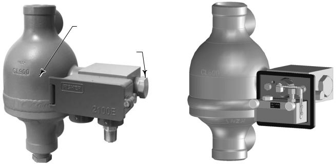
Figure 4. Fisher 2100E Electric Liquid Level Switch |
Figure 5. Fisher 2100 Pneumatic Liquid Level Switch |
|
|
|
|
|
APPROXIMATE
SWITCHING POINT
LOCATION OF
OPTIONAL
SIGHT WINDOW
X0682 |
W9954-1 |
Fisher 2100 Liquid Level
Switches
Typically, 2100E and 2100 switches electrically or pneumatically operate safety shutdown systems for field processing equipment in oil and gas industry applications
Switch construction comes in a left hand as well as a right hand mounting version. The explosion proof, hermetically sealed 2100E switch is offered as both a factory mounting and as an electric switch retrofit to the proven 2100 switch.
With the 2100E switch rising liquid level exerts a buoyant force on the torque tube that either activates or deactivates an electrical SPDT or DPDT switch
depending on the switching action desired. Falling liquid level deactivates or activates the same switch depending on the action desired.
When the 2100 switch is in the normal position with the flapper against the nozzle, output pressure cannot bleed off and remains the same as full supply pressure. Rising liquid level exerts a buoyant force on the displacer, producing a torque on the torque tube. When the torque transmitted by the torque tube exceeds the torque exerted on the flapper by the magnet, the flapper snaps away from the nozzle, allowing output pressure to bleed through the nozzle faster than supply pressure can enter through the bleed orifice. The reduced pressure in the output signal line activates the shutdown or alarm system. When the liquid level lowers, the falling displacer forces the flapper into the field of the magnet, letting the magnet snap the flapper against the nozzle and causing output pressure to build to full supply pressure.
5
 Loading...