


Ultra® 325 TT Automation Series
Ultra® 525 TT Automation Series
Quick Start Installation Guide
Electronic pdf files of EFD® manuals are also available at www.efd-inc.com/manuals.html
Socket™ adapter |
|
||
attached |
|
||
to RS232 |
Main |
||
|
|
|
Power |
|
|
|
Circuit |
|
Ethernet |
|
Breaker |
|
|
|
|
Discrete I/O |
|
|
|
Safety |
Exhaust |
Main Power Input |
General |
|
General |
Fan |
|
||
|
Purpose |
|
Purpose |
Interlock |
Main Air |
|
|
Outputs |
|
Inputs |
|
|
|
|
|
|
|
|
Entry |
|
|
|
|
|
|
|
|
|
|
|
|
|
|
|
T Slots
Dispense Valves
Universal Fixture
Pressure Gauges
Pressure Regulators
Vacuum Control
Interactive LCD
PDA/Serial Connector
®
A NORDSON COMPANY
Z-head Electrical /
Air Connections
Mounting
Bracket
 Power Button
EMO Button
Palm™ handheld
Valve/Dispensing Device Configuration
|
|
Air Connections |
Air Connections |
Fluid Pressure Connection |
|
|
|
|
|
EFD Valve Model |
|
|
|
|
|
||||
|
|
(actuating) |
(atomizing) |
|
|
|
|
|
|
|
|
|
|
|
|
|
|
||
|
|
P1 |
N/A |
P2 or Auxiliary Air |
|
|
|
|
|
752V-UHSS |
|
|
|
|
|
||||
|
|
P1 |
N/A |
P2 or Auxiliary Air |
|
|
|
|
|
725DA-SS |
|
|
|
|
|
||||
|
|
P1 |
N/A |
P2 or Auxiliary Air |
|
|
|
|
|
725HF-SS |
|
|
I/O Dispense Head |
||||||
|
|
P1 |
N/A |
P2 or Auxiliary Air |
|
|
|
|
|
740V-SS |
|
|
|
|
|
||||
|
|
P1 |
N/A |
P2, Auxiliary Air or customer supplied |
|
|
|
|
|
736HPA |
|
|
|
HS |
|||||
|
|
P1 |
P2 |
Auxiliary Air |
|
|
|
|
|
780S-SS |
|
P1 P2 |
AUX AIR |
||||||
|
|
Terminal 1+ Terminal 2 - |
N/A |
P2 Selectable between pulsed or |
|
|
|
|
|
790 |
|
|
|
|
|
||||
|
|
|
|
constant pressure |
|
|
|
|
|
|
|
|
|
|
|
|
|
|
|
|
|
P1 |
N/A |
Same as actuating |
|
|
|
|
|
Syringe Barrel 0~100 psi |
|
|
|
|
|
||||
|
|
P2 |
N/A |
Same as actuating |
|
|
|
|
|
Syringe Barrel 0~30 psi |
|
|
|
|
|
||||
|
|
P1 |
N/A |
Same as actuating |
|
|
|
|
|
5800MP |
|
P1 = 0~100 psi |
|||||||
|
|
P1 |
N/A |
Same as actuating |
|
|
|
|
|
HP4X™ |
|
P2 = 0~30 psi |
|||||||
|
|
P1 |
N/A |
Same as actuating |
|
|
|
|
|
HP7X™ |
|
|
|
|
|
||||
|
|
N/A |
N/A |
N/A |
|
|
|
|
|
2800 |
|
|
|
|
|
||||
|
|
|
|
|
|
|
|
|
|
1
7 Step Easy Setup
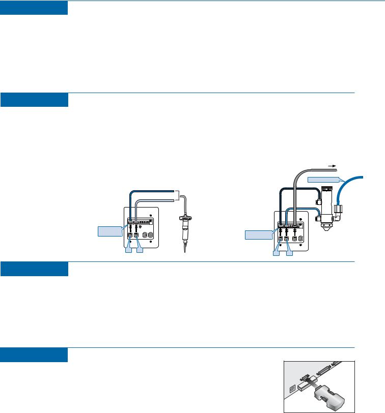
Electrical
1
Use the power cord provided and plug the machine into the 100 ~ 240VAC, single-phase power source. This machine uses a self-regulating power supply and will work on any voltage in the stated range. The electrical connection is located on the back left-hand side of the machine.
Mounting
Step 3: Syringe Barrel
3 |
Locate and install the universal syringe barrel bracket (#700814). |
Insert the holding pins into the holes on the back plate to fit the |
|
size barrel you are using. Insert the luer end of the barrel into the |
|
barrel stop and twist the barrel onto the captive luer extender. |
|
Attach the barrel adapter to barrel and plug the male quick connect |
|
into the P1 connector (0~100 psi) for dispensing high-viscosity |
|
fluid or P2 (0~30 psi) for dispensing low-viscosity fluid. Attach your |
|
dispensing tip to the bottom of the luer extender |
Step 3: Multi Air Input Valve
Attach the valve to the appropriate valve bracket. Install the valve bracket onto the machine. Attach pulsed-air line to the P1 connector and then attach the pulsed nozzle air to the P2 connector on top of the Z-head. Fluid reservoir air is connected to the auxiliary air connector on top of the Z-head.
To pressurized reservoir or cartridge
0-100 psi
Black (male) |
|
HS |
P1 P2 |
AUX AIR |
|
quick-connect |
|
|
Black (male) quick-connect
I/O |
 HS
HS
P1 P2 |
AUX AIR |
LVLP spray valve
P1 P2
P1 P2
Height Sensor
4
Adjust the height sensor probe so it is located approximately 25.0mm above the dispense tip when the probe is not actuated. The height sensor is attached to the backside of the Z-plate. This will allow enough room for the dispense tip to reach the parts without obstruction from the probe. To make the required adjustment, loosen the probe hold-down screw and slide probe either downwards or upwards. Hand tighten only; do not overtighten probe hold down screw or it will deform the probe. This should give you an approximate 22mm offset between tip and probe. You must still teach the offset as described in the setup section in the manual to complete configuring your machine.
Start-up
6
Remove the bolt at the top right-hand corner of the Z-plate. This bolt was any movement of the Z-carriage during shipping.
Download the Software Installation CD that was included with the PDA to the done download the EFD PDA software to the PC. Copy the EFD PDA software Quick Install and then HotSync to install the EFD PDA software to the palm.
Connect the Socket Bluetooth® adapter to the RS232 connector at the back of Turn the main power circuit breaker at the back of the machine ON. Reset the EMO switch on
the front panel and press the green power button to power up the machine. Check that the Socket adapter LED is blinking.
Start the EFD software on your PDA handheld. Go to Tools and open the Bluetooth window. Tap Discover and wait for Socket #1 to appear in the Device list. Highlight this device and tap Connect. When the Security screen opens, type “1234” and press OK. (Do not check “Add to trusted device list”.) Wait for the message “Connection established to selected device”. Tap Done. Return to the Main screen, select Setup and the message “Dispenser is about to Home” will display. Tap OK to home the machine.
2
 Loading...