


 Loading...
Operating Guide
2000XL Series Digital Dispensers
2000XL • 2000XL-PR5-15 • 2000XL-CA
|
Cell Select |
Time Set |
® |
|
Pressure |
|
|||
|
|
Fast |
Slow |
A NORDSON COMPANY |
|
|
|
|
STEADY |
|
|
|
|
RUN |
Vacuum |
|
|
|
SETUP |
|
|
|
|
CYCLE |
Vacuum |
Run |
Steady |
Fast |
Slow |
Pressure STOP |
|
Pressure |
||||||
Setup |
Teach |
Time Set |
Time |
|||
|
||||||
®
In the US: 800-556-3484 In the UK: 0800 585733 In Mexico: 001-800-556-3484
A NORDSON COMPANY
Introduction
The 2000XL Series dispensers provide years of trouble-free, productive service. This Operating Guide will help you maximize the usefulness of your new dispenser.
Please spend a few minutes to become familiar with the controls and features of your new dispenser. Follow our recommended testing procedures. Review the helpful information we have included based on over 30 years of industrial dispensing experience.
Most questions you will have are answered in this guide. However, if you need assistance, please do not hesitate to contact EFD or your
authorized EFD distributor.
In the US, call 800-556-3484.
In Mexico, call 001-800-556-3484.
In the UK, ring free 0800 585733.
The EFD Pledge
We pledge that you will be completely satisfied with our products. We endeavor to ensure that every EFD product is produced to our no-compromise quality standards.
If you feel that you are not receiving all the support you require, or if you have any questions or comments, I invite you to write or call me personally.
Our goal is to build not only the finest equipment and components, but also to build long-term customer relationships founded on superb quality, service, value and trust.
Randall Richardson, President
This manual is for the express and sole use of EFD dispenser purchasers and users, and no portion of this manual may be reproduced in any form.
Contents
Getting Started ............................................................................. |
|
4 |
Specifications |
|
|
First Steps .................................................................................... |
|
5 |
Unpacking the dispenser & Activating your Ten Year No-fault Warranty |
||
Features and Controls .............................................................. |
|
6-7 |
Indicator Lamps ....................... |
7 |
|
Setup ..................................................................................... |
|
8-10 |
Setup procedures .................. |
8-9 |
|
Diagram ................................. |
10 |
|
Final checklist ........................ |
10 |
|
Testing the 2000XL .............................................................. |
|
11-12 |
Programming deposit size ..... |
12 |
|
Operational Features ................................................................. |
|
13 |
ULTRA Dispensing System .................................................. |
|
14-15 |
How to Use the Vacuum Control .......................................... |
16-17 |
|
Loading the Barrel Reservoirs .............................................. |
18-19 |
|
Memory Function ................................................................. |
|
20-21 |
Input and Output Connection Instructions ................................. |
22 |
|
Schematic and Replacement Parts List ..................................... |
23 |
|
Troubleshooting ......................................................................... |
|
24 |
Suggestions and Reminders ...................................................... |
25 |
|
Reordering Components ............................................................ |
|
26 |
Ten Year No-fault Warranty |
....................................................... |
27 |
Meets applicable CSA and CE requirements.
EFD, ULTRA System, LV Barrier and SmoothFlow are trademarks of EFD Inc. ©2002 EFD Inc.
Getting Started
The 2000XL Series automatic fluid dispensers are designed to provide complete process control using advanced microprocessor circuitry. All microprocessor functions are accessed by push button.
Microprocessor features include:
•Push-button time setting input or one-touch time programming.
•Floating decimal, providing dispense time ranges of 0.001 to 9.999 and 00.01 to 99.99 seconds.
•Backlit LCD displays time settings, dispensing pressure and vacuum pressure.
•Dispensing pressure display is programmable for either psi or bar scale.
•Memory with storage for up to eight separate time settings.
Intelligent technology makes the 2000XL Series easy to set up and use. With one-touch setup, just press the pedal to determine the proper amount. The microprocessor remembers the time and repeats this amount with each cycle until you are ready to change it.
From microdeposits to volumetric filling, the 2000XL provides the ultimate in control and versatility for time/pressure-based fluid dispensing.
|
|
|
|
|
|
|
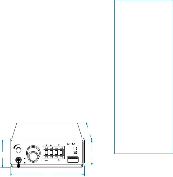
5.570" |
|
|
|
|
|
|
|
14.1 cm |
|
Pressure |
Cell Select |
Time Set |
|
2000XL |
||
|
|
|
|
Fast |
Slow |
A NORDSON COMPANY |
|
|
|
|
|
|
|
STEADY |
|
|
|
|
|
|
|
RUN |
2.700" |
3.380" |
|
|
|
|
|
SETUP |
|
Vacuum |
|
|
|
|
CYCLE |
6.9 cm |
|
8.6 cm |
|
|
|
|
|
|
|
|
|
|
|
|
|
|
|
|
Vacuum |
Run |
Steady |
Fast |
Slow |
Pressure |
STOP |
|
Pressure |
Setup |
Teach |
Time Set |
Time |
|
|
Specifications
Cabinet size: |
Weight |
7.470 x 5.570 x 2.700" |
3 lb 3 oz |
(19.0 x 14.1 x 6.9 cm) |
1.44 kg |
Input voltage:
Selectable 100/120/220 VAC 50/60 Hz 10/9 VA
End-of-cycle feedback circuits:
5 to 24 VDC N.C. solid-state switch 250mA maximum (details page 23)
Initiate circuit: Foot pedal or 5 to 24 VDC signal
Air consumption: Approximately 1.5 SCFM at 400 cycles per minute
Cycle rate: Exceeds 600 per minute
Time range: Programmable 0.001 to 9.999, or 00.01 to 99.99 seconds
2000XL air input:
80 to 100 psi (5.5 bar to 6.9 bar) air output:
0 to 100 psi (0 to 6.9 bar)
2000XL-PR5 air input:
10 to 50 psi (0.7 bar to 3.4 bar) air output:
0 to 5 psi (0 to .34 bar)
2000XL-CA air input:
80 to 100 psi (5.5 bar to 6.9 bar) air output:
0 to 15 psi (0 to 1.0 bar)
Note: Specifications and technical details are subject to engineering changes without prior notification.
7.470" 19.0 cm

First Steps
First: Unpack and use the checklist enclosed with the Dispenser Kit to identify all items. If there is any discrepancy, please call us immediately.
Second: Power and compressed plant air should be available where the dispenser is to be set up. Input air should be set between 80 and 100 psi (5.5 and 6.9 bar). For model 2000XL-PR5, input air should be set between 10 and 50 psi (0.7 and 3.4 bar). If you are not using an EFD five-micron filter regulator #2000F755, be certain your plant air is properly filtered and dry and a regulated, constant air pressure is supplied to the dispenser.
Note: Model 2000XL-CA is supplied with an EFD five-micron filter regulator with coalescing filter (#2000F756).
Bottled nitrogen can be used.
Warning: If high pressure bottled air or nitrogen is used, a high pressure regulator must be installed on the bottle and set at 100 psi maximum. The 2000F755 filter regulator is not required.
Check the voltage label to be certain it is set to the available power.
Third: Now is a good time to ACTIVATE your extended Ten Year No-fault Warranty. Please fill in and return the postage paid Warranty card. Or if you prefer, call the appropriate toll-free number listed below, provide the serial number of your dispenser and respond to a few short questions.
In the US, call 800-556-3484.
In Mexico, call 001-800-556-3484.
In the UK, ring free 0800 585733.
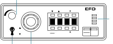
Features and Controls
Barrel vacuum |
|
control |
|
|
Pressure |
Vacuum |
|
Vacuum |
|
Pressure |
|
Vacuum |
Air pressure |
toggle switch |
regulator |
Digital Time, Air Pressure and
Vacuum Pressure LCD Display
•Programmable floating decimal provides time range readout from 0.001 to 99.99 seconds.
•Air pressure readout can be programmed in either psi or bar.
•Vacuum pressure readout is displayed by holding the vacuum toggle switch in the "up" position.
Memory
Can store up to eight Time settings. (See page 20.)
Run/Setup
1.The RUN mode allows access to all eight cells. Cell numbers are displayed as CEL1, CEL2....CEL8. Changing the cell number will change the time setting corresponding to that cell.
The SETUP mode provides access to selected cell TEACH and TIME SET functions. Only in the SETUP mode can cell time values be viewed, cleared, or changed.
2.In the RUN mode, the functions are inoperative.
Steady/Teach
In SETUP mode, pressing STEADY/TEACH will clear the currently displayed cell setting, reset the cell display to blinking "0000", and place the dispenser
|
|
|
|
|
® |
Cell Select |
Time Set |
|
2000XL |
||
|
|
Fast |
Slow |
A NORDSON COMPANY |
|
|
|
|
|
STEADY |
Function |
C |
E |
L |
1 |
RUN |
|
SETUP |
Indicator |
||||
CYCLE |
|||||
|
|
|
|
|
Lamps |
Run |
Steady |
Fast |
Slow |
Pressure |
STOP |
Setup |
Teach |
Time Set |
Time |
|
|
in a TEACH mode (refer to page 12 for TEACH procedures).
In RUN mode, pressing STEADY/TEACH will override the timer and dispense for as long as the foot pedal is pressed. The dispenser display will read "----" in the
STEADY mode.
Time Set ▼(down) ▲ (up)
In SETUP mode, use the TIME SET buttons to change time settings. Left buttons scroll digits quickly; right buttons scroll digits slowly.
Pressure/Time
Press to change display values from TIME to PRESSURE or PRESSURE back to TIME.
In SETUP mode, pressure readings may be changed from PSI to BAR and BAR to PSI by pressing and holding the PRESSURE/TIME button for four seconds.
STOP
This button stops the dispenser immediately.
Barrel Vacuum Control
Refer to page 16 for operation.
Air Pressure Regulator
Refer to page 11 for operating instructions.
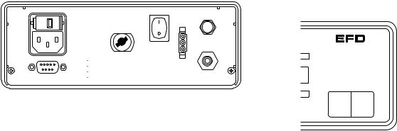
Voltage selector |
|
|
|
Air output |
Power |
Foot pedal |
|
|
|
|
|
|
|
|
|
|
|
|||||||||
and fuse cartridge |
|
quick-connect |
switch |
receptacle |
Indicator Lamps |
|||||||||||||||||||||
|
|
|
|
|
|
|
|
|
|
|
|
|
Exhaust |
|||||||||||||
|
|
|
|
|
|
|
|
|
|
|
|
|
|
|
|
|
|
|
|
|
|
|
|
|||
|
|
|
|
|
|
|
|
|
|
|
|
|
|
|
|
|
|
|
|
|
|
|
|
|
|
|
|
|
|
|
|
|
|
|
|
|
|
|
|
|
|
|
|
|
|
|
|
|
|
|
|
|
|
|
|
|
|
|
|
|
|
|
|
|
|
|
|
|
|
|
|
|
|
|
|
|
|
|
|
|
|
|
|
|
|
Fuse T 125mA 250V |
|
|
|
|
Exhaust |
|
|
|
|
|
|
|
|
|
|
|
|||||
|
|
|
|
|
|
|
|
Foot |
|
|
|
|
|
|
|
|
|
|
|
|||||||
|
|
|
|
|
100/120/220VAC |
Air |
|
|
Pedal |
|
|
|
|
|
|
|
|
|
|
|
||||||
|
|
|
|
|
50/60Hz 10/9VA |
|
|
|
|
|
|
|
|
|
|
|
|
|
|
|
|
|||||
|
|
|
|
|
|
|
|
Output |
|
|
|
|
|
|
|
|
|
|
|
|
|
|
|
|
||
|
|
|
|
|
|
|
|
|
|
|
|
|
|
|
|
|
|
|
® |
|
|
|||||
|
|
|
|
|
|
|
|
|
|
|
|
|
|
|
|
t |
|
|
|
|
|
2000XL |
||||
|
|
|
|
|
|
|
|
|
|
|
|
|
Air |
|
low |
|
A NORDSON COMPANY |
|||||||||
|
|
|
|
|
|
|
|
|
|
|
|
|
Input |
|
|
|
|
|
|
|
|
|
|
|
||
|
|
|
|
|
|
|
|
|
|
|
|
|
|
|
|
|
|
|
|
|
|
|||||
|
|
|
|
|
1. Initiate + |
|
5-24 VDC |
5. Contact Closure |
|
|
|
|
|
|
|
|
|
|
STEADY |
|
|
|
||||
|
|
|
|
|
|
|
|
|
|
|
|
|
|
|
|
RUN |
|
|
|
|||||||
|
|
|
|
|
2. Initiate - |
|
6. Chassis Ground |
|
|
|
|
|
|
|
|
|
|
|
|
|
||||||
|
|
|
|
|
3. Output + |
|
|
7. Contact Closure |
|
|
|
|
|
|
|
|
|
|
|
|
|
|
|
|
||
|
|
|
|
|
|
5-24 VDC |
8. Not Used |
|
|
|
|
|
|
|
|
|
|
SETUP |
|
|
|
|||||
|
|
|
|
|
4. Output - |
|
250mA |
9. Not Used |
|
|
|
|
|
|
|
|
|
|
|
|
|
|
|
|
||
|
|
|
|
|
|
|
|
|
|
|
|
|
|
|
|
|
|
|
|
CYCLE |
|
|
||||
|
|
|
|
|
|
|
|
|
|
|
|
|
|
|
|
|
|
|
|
|
|
|
|
|
||
|
|
|
|
|
|
|
|
|
|
|
|
|
|
|
|
|
|
|
|
|
|
|
|
|
|
|
Power input |
I/O 9 pin interface |
|
|
|
Air input |
|
|
|
|
|
|
|
|
|
|
|
||||||||||
|
|
|
|
|
|
Pressure STOP |
||||||||||||||||||||
|
|
|
low |
|||||||||||||||||||||||
receptacle |
connector |
|
|
|
|
|
|
|
|
|||||||||||||||||
|
|
|
|
|
|
|
|
t |
|
Time |
||||||||||||||||
|
|
|
|
|
|
|
|
|
|
|
|
|
|
|
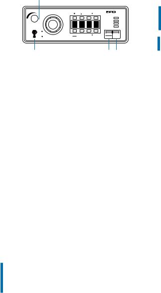
In the upper right corner of the |
|||||||||||
Power Input Receptacle with Voltage Selector and Fuse Cartridge |
front panel are four indicator |
|||||||||||||||||||||||||
lamps. These lamps indicate |
||||||||||||||||||||||||||
Three input voltages can be used: 100 VAC, 120 VAC and 220 VAC. To |
the mode of operation. |
|||||||||||||||||||||||||
change input voltage, remove fuse cartridge and position the selected |
STEADY - Indicates that the |
|||||||||||||||||||||||||
voltage marked on the cartridge so that it shows through the window. |
||||||||||||||||||||||||||
timing feature has been |
||||||||||||||||||||||||||
(Details on page 8.) |
|
|
|
|
|
|
|
|||||||||||||||||||
|
|
|
|
|
|
|
overridden and that the output |
|||||||||||||||||||
|
|
|
|
|
|
|
|
|
|
|
|
|
|
|
||||||||||||
Input/Output 9 Pin Interface Connector |
|
|
|
|
|
is controlled by the length of |
||||||||||||||||||||
The input/output features are used when the dispenser is interfaced with |
time the foot pedal is pressed. |
|||||||||||||||||||||||||
|
|
|
|
|
|
|
|
|
|
|
||||||||||||||||
external control circuits. |
|
|
|
|
|
|
|
RUN - Indicates that the |
||||||||||||||||||
• An End-of-Cycle signal, in the form of a solid-state switch, closes upon |
dispenser is in the RUN mode |
|||||||||||||||||||||||||
completion of the dispense cycle. Maximum load is 250mA from 5 to |
ready to be initiated through a |
|||||||||||||||||||||||||
dispense cycle. In this mode, |
||||||||||||||||||||||||||
24 VDC. |
|
|
|
|
|
|
|
|
|
|
|
|||||||||||||||
|
|
|
|
|
|
|
|
|
|
|
time settings cannot be |
|||||||||||||||
• The 2000XL can be initiated using a 5 to 24 VDC signal. |
||||||||||||||||||||||||||
changed. |
|
|
|
|
|
|
|
|||||||||||||||||||
|
|
|
|
|
|
|
|
|
|
|
|
|
|
|
|
|
|
|
|
|
|
|||||
• Contact Closure. |
|
|
|
|
|
|
|
SETUP - Indicates that the |
||||||||||||||||||
|
|
|
|
|
|
|
|
|
|
|
|
|
|
|
||||||||||||
(For more details, refer to page 22.) |
|
|
|
|
|
dispenser is in the SETUP |
||||||||||||||||||||
|
|
|
|
|
|
|
|
|
|
|
|
|
|
|
mode. In this mode, time |
|||||||||||
|
|
|
|
|
|
|
|
|
|
|
|
|
|
|
settings can be changed. |
|||||||||||
|
|
|
|
|
|
|
|
|
|
|
|
|
|
|
CYCLE - This lamp is on during |
|||||||||||
|
|
|
|
|
|
|
|
|
|
|
|
|
|
|
the dispense cycle. |
|||||||||||
|
|
|
|
|
|
|
|
|
|
|
|
|
|
|
|
|
|
|
|
|
|
|
|
|
|
|
Setup
Power switch should be off.
Mounting
Included is a universal mounting bracket. Mounting hardware is installed into the four 10-32 mounting holes on the sides of the cabinet. The bracket can be mounted either over or under the cabinet and will allow the dispenser to pivot up or down 30° from a horizontal position. The bracket may be permanently mounted, or attach the rubber feet included and use the bracket as a bench-top tilt stand. Four rubber feet on the console are provided if the bracket is not used.
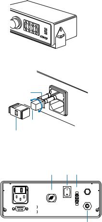
Input power
Check the input power cord receptacle. To change voltage, remove the voltage selector from the cartridge, rotate it and position the correct voltage to show through the cartridge window. Replace the cartridge into the power cord receptacle and insure that both sides snap securely into position.
Install the power cord.
Initiate connection
The 2000XL is normally operated using the foot pedal supplied. Plug the foot pedal into the connector located on the rear panel. An alternate method is to apply a 5 to 24 VDC pulse to terminals 1 and 2.
Air input connection
A 6 ft. air input hose kit is supplied. Connect the input hose to filtered, dry plant air. For models 2000XL and 2000XL-CA, set plant air supply within 80 to 100 psi (5.5 to 6.9 bar). For model 2000XL-PR5, input air should be set within 10 to 50 psi (0.7 to 3.4 bar).
Attach the air input hose coupling to the dispenser. Pull back metal ring to attach to dispenser.
Spare fuse
120 |
220 |
|
|
001 |
|
Voltage value
Cartridge window
Note: Check voltage indicated
Fuse T 125mA 250V |
Exhaust |
|||
100/120/220VAC |
|
Foot |
||
|
Pedal |
|||
50/60Hz 10/9VA |
Air |
|
||
|
|
|
Output |
|
|
|
|
|
Air |
|
|
|
|
Input |
1. |
Initiate + |
5-24 VDC |
5. Contact Closure |
|
2. |
Initiate - |
6. Chassis Ground |
|
|
|
Output + 5-24 VDC |
7. Contact Closure |
|
|
3. |
8. Not Used |
|
||
4. Output - |
250mA |
9. Not Used |
|
|
Note: If filtered, dry air is not available, order an EFD five-micron filter regulator #2000F755.
(2000XL-CA units are supplied with a five-micron coalescing filter regulator.)
|
Cell Select |
Time Set |
|
® |
||
Pressure |
|
2000XL |
||||
|
|
|
Fast |
Slow |
A NORDSON COMPANY |
|
|
|
|
|
|
STEADY |
|
|
C |
E |
L |
1 |
RUN |
|
|
CYCLE |
|
||||
Vacuum |
|
|
|
|
SETUP |
|
Vacuum |
|
|
|
|
Pressure |
|
Pressure |
Run |
Steady |
Fast |
Slow |
STOP |
|
|
Setup |
Teach |
Time Set |
Time |
|
|
|
|
|
|
|
|
|
Power on/off
Press the Power Switch located on the rear panel to the "ON" position. The dispenser will power up in the RUN, STEADY, or PRESSURE mode and indicate which cell was selected last. (Dispenser is shipped with CEL1 selected in RUN mode).
Air output
Push in and twist lock the 10cc adapter assembly (part # 1000Y5150). The number 5150 is molded on the side of the yellow head.
Setting the decimal
The dispenser is shipped with the decimal set at hundredths of a second (00.00). The decimal can be moved to show thousandths of a second (0.000) as follows:
Press RUN/SETUP to place the dispenser in SETUP mode.
To move the decimal, press and hold the STOP button. After approximately 4.0 seconds, the decimal will move to the thousandths position. To return to the hundredths position, press and hold the STOP button again.
Note: Changing the decimal place changes the current time setting by a factor of 10. For example, 5.35 seconds becomes 53.50; 15.00 seconds becomes 1.50.
Setting the pressure readout
The dispenser is shipped with pressure display programmed in psi.
Note: On models with 5 psi and 15 psi regulators, the pressure is adjustable in 0.1 psi increments.
If bar is desired, change as follows:
Press RUN/SETUP and place the dispenser into the SETUP mode. Press and hold the PRESSURE/TIME button for 4.0 seconds. The display will change from psi to bar. To change back to psi, press and hold PRESSURE/TIME for 4.0 seconds.
Vacuum control
Vacuum is turned off (clockwise) during testing procedures. (Refer to page 16 for operation.)
Vacuum toggle switch
To read vacuum pressure, hold toggle switch in the "up" position. Readout will appear on the digital display pad, then return to air pressure readout when toggle is released.
Continue to page 11 for test procedures.
Loading...