


800
Table of contents
 Loading...
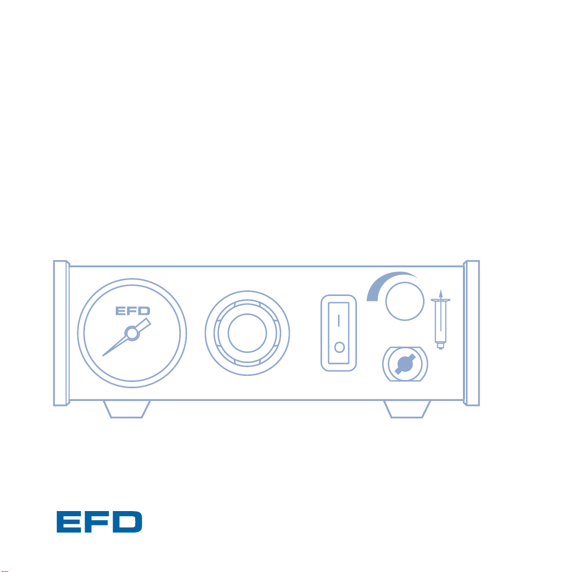
Operating Guide
Model 800 Dispenser
®
A NORDSON COMPANY
US: 800-556-3484 In the UK: 0800 585733 In Mexico: 001-800-556-3484

☎
Introduction
Model 800 fluid dispenser provides years of trouble-free, productive
service. This Operating Guide will help you maximize the usefulness
of your new dispenser.
Please spend a few minutes to become familiar with the controls and
features of your new dispenser. Follow our recommended testing
procedures. Review the helpful information we have included based
on over 30 years of industrial dispensing experience.
Most questions you will have are answered in this Guide. However,
if you need assistance, please do not hesitate to contact EFD or your
authorized EFD distributor.
In the US, call 800-556-3484.
In Mexico, call 001-800-556-3484.
In the UK, ring free 0800 585733.
The EFD Pledge
We pledge that you will be completely satisfied with our products.
We endeavor to ensure that every EFD product is produced to our
no-compromise quality standards.
If you feel that you are not receiving all the support you require,
or if you have any questions or comments, I invite you to write or call
me personally.
Our goal is to build not only the finest equipment and components,
but also to build long-term customer relationships founded on superb
quality, service, value and trust. Randall Richardson, President
Model 800 Specifications
Input voltage: Selectable
100/120/220 VAC 50/60Hz 26/20 VA
Air input: 80 to 100 psi (5.5 to 6.9 bar)
Internal voltage: 24 VAC
Foot pedal voltage: 24 VAC
800
7¼ x 8½ x 2⅝" 3 lb 4 oz
(18.4 x 21.6 x 6.7 cm) (1.48 kg)
Air output: 0 to 100 psi (0 to 7.0 bar)

First: Unpack and use the checklist enclosed with
the Dispenser Kit to identify all items. If there is
any discrepancy, please call us immediately.
Second: Power and compressed plant air should
be available where the dispenser is to be set up.
Air pressure should be between 80 and 100 psi
(5.5 and 6.9 bar). If you are not using an EFD five-
micron filter regulator #2000F755, be certain
your plant air is properly filtered and dry.
Bottled nitrogen can be used.
Warning: If high pressure bottled air or nitrogen is
used, a high pressure regulator must be installed
on the bottle and set up at 100 psi maximum. The
#2000F755 filter regulator is not required.
Check the voltage label to be certain it is set to
the available power.
Third: Now is a good time to ACTIVATE your
extended Two Year Limited Warranty. Please fill
in and return the postage paid Warranty card. Or
if you prefer, call the appropriate toll-free number
listed below, provide the serial number of your
dispenser and respond to a few short questions.
You are then assured of complete protection for
two years.
US, call 800-556-3484.
In Mexico, call 001-800-556-3484.
In the UK, ring free 0800 585733.
This manual is for the express and sole use of EFD dispenser purchasers
and users, and no portion of this manual may be reproduced in any form.
EFD, ULTRA System, LV Barrier, SmoothFlow, ZeroDraft, SafetyLok,
SnapLok and DispenStand are trademarks of EFD Inc. ©2001 EFD Inc.
Contents
Dispenser Hookup.................................... 4-5
Controls & Connections .............................. 6
Setup for Testing......................................... 7
Testing the Dispenser ................................. 8
Using the Vacuum Control .......................... 9
ULTRA Dispensing System.................. 10-11
Loading the Barrel Reservoirs.............. 12-13
Suggestions & Reminders......................... 14
Components Reorder................................ 15
Two Year Limited Warranty....................... 16
Meets applicable CSA and CE requirements.
Reference CSA LR File Number 84105
First Steps
☎
800
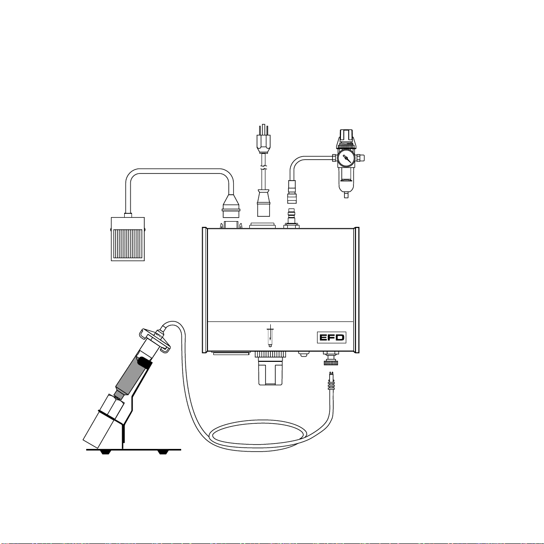
Plant air, 125 psi maximum to
regulator. Output from regulator
should be a minimum of 80 psi,
maximum 100 psi.
❶
❷
Check voltage label
on dispenser
❸
❼
Male quick-connect,
insert and twist to lock
❹
❻
❺
Air input
hose
Power cord
Adapter
assembly
Foot pedal
assembly
Blue test
fluid
Dispenser Hookup
❶ Connect the air input hose to a plant air source.
Set plant air supply within 80 to 100 psi (5.5 to 6.9
bar). Where required, use an EFD five-micron
filter regulator #2000F755 (see Warranty).
❷ Attach the air input hose coupling to the dispenser.
Pull back metal ring to attach to dispenser.
❸ Plug in the polarized, foot pedal connector.
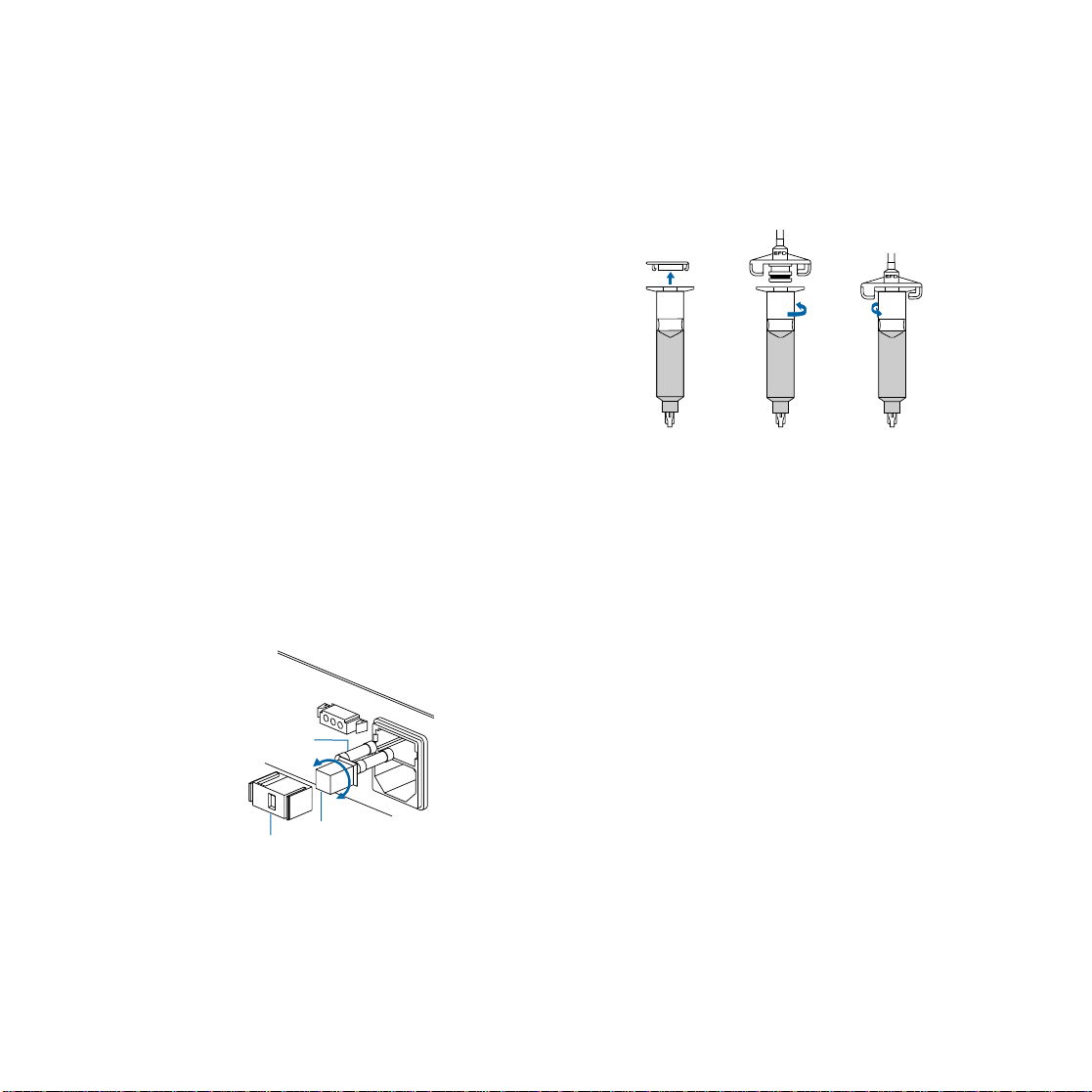
❹ Check the voltage label on the input voltage
selector cartridge. To change the voltage,
remove the voltage selector from the cartridge,
rotate it and position the correct voltage to show
through the cartridge window. Replace the
cartridge into the power cord receptacle and
insure that both sides snap securely into position.
Install the power cord.
Spare Fuse
Cartridge Window
(check voltage indicated)
Voltage Value
❺ Attach the 10cc barrel prefilled with blue,
nontoxic test fluid (included with the
dispenser) to the 10cc adapter head.
❻ Take the 10cc barrel adapter assembly
(#5150 on the adapter head) and insert the
black, male quick-connect into the air output
fitting on the front panel and turn clockwise
to lock. Place the barrel in the barrel stand.
❼ During the initial testing, you will not use the
vacuum control. Keep this control shutoff
(turned completely clockwise—do not force).
220
120
100
Note: The dispenser is shipped with the fuse
cartridge set for 120 VAC input.
Loading...