


 Loading...
Operating Guide
1000 Series Dispensers
1000XL • 1000D
®
In the US: 800-556-3484 In the UK: 0800 585733 In Mexico: 001-800-556-3484
A NORDSON COMPANY
Introduction
The 1000 Series dispensers provide years of trouble-free, productive service. This Operating Guide will help you maximize the usefulness of your new dispenser.
Please spend a few minutes to become familiar with the controls and features of your new dispenser. Follow our recommended testing procedures. Review the helpful information we have included based on over 30 years of industrial dispensing experience.
Most questions you will have are answered in this Guide. However, if you need assistance, please do not hesitate to contact EFD or your
authorized EFD distributor.
In the US, call 800-556-3484.
In Mexico, call 001-800-556-3484.
In the UK, ring free 0800 585733.
The EFD Pledge
We pledge that you will be completely satisfied with our products. We endeavor to ensure that every EFD product is produced to our no-compromise quality standards.
If you feel that you are not receiving all the support you require, or if you have any questions or comments, I invite you to write or call me personally.
Our goal is to build not only the finest equipment and components, but also to build long-term customer relationships founded on superb quality, service, value and trust. John Carter, President
This manual is for the express and sole use of EFD dispenser purchasers and users, and no portion of this manual may be reproduced in any form.
EFD, ULTRA System, LV Barrier, SmoothFlow, ZeroDraft, SafetyLok, SnapLok and DispenStand are trademarks of EFD Inc. ©2004 EFD Inc.
Contents |
|
Getting Started ............................................................................. |
4 |
Specifications |
|
First Steps .................................................................................... |
5 |
Unpacking the Dispenser and Activating your Ten Year No-fault Warranty |
|
1000XL - Hookup ...................................................................... |
6-7 |
1000XL - Setup for Testing ....................................................... |
8-9 |
1000D - Hookup .................................................................... |
10-11 |
1000D - Setup for Testing ..................................................... |
12-13 |
Testing the 1000 Series Dispensers ..................................... |
14-15 |
Making Timed Deposits |
|
Changing Deposit Size |
|
Drawing Stripes |
|
ULTRA Dispensing System ................................................... |
16-17 |
How to Use the Vacuum Control ........................................... |
18-19 |
1000XL only |
|
Loading the Barrel Reservoirs............................................... |
20-21 |
Now, Test Your Fluid .................................................................. |
22 |
Troubleshooting ......................................................................... |
23 |
1000XL and 1000D Schematic & Parts ...................................... |
24 |
1000 Series Programmable Timer ............................................. |
25 |
Suggestions & Reminders .......................................................... |
26 |
Components Reorder ................................................................. |
27 |
Ten Year No-fault Warranty ....................................................... |
28 |
Meets applicable CSA and CE requirements. |
|
Reference CSA LR File Number 84105 |
|

Getting Started
We have organized this Guide to provide setup and testing procedures for the 1000XL and 1000D dispensers.
If you have the 1000XL, first review pages 6 - 9 which illustrate how to hook up the dispenser and what the controls do.
For the 1000D, review pages 10 - 13.
Next, pages 14 - 15 show how to dispense the thick, paste-like test material included in the Test Kit. These instructions are common to both 1000 Series dispensers.
Finally, pages 18 - 19 illustrate how to dispense low-viscosity liquid using the vacuum control provided on the 1000XL.
The rest of the information in this Guide applies to both of the 1000 Series dispensers.
1000 Series Specifications
Input voltage: Selectable 100/120/220 VAC 50/60 Hz 16/13 VA
Internal voltage: 24 VDC
Foot-pedal voltage: 9 VDC
Air input: |
80 to 100 psi |
|
(5.5 to 6.9 bar) |
Air output: |
0 to 100 psi |
|
(0 to 6.9 bar) |
Cycle rate: |
> 600/minute |
Time repeat: ±0.1%
Initiation: maintained or momentary
Time Range: programmable (seconds) 0.005 to 0.04 sec.
0.01to 1.0 sec.
0.1to 10 sec.
0.2to 20 sec.
0.3to 31 sec.
1000XL |
|
10⅜ x 8½ x 2⅝ |
5 lb 12 oz |
26.4 x 21.6 x 6.7 cm |
2.63 kg |
1000D |
|
8⅝ x 8½ x 2⅝ |
4 lb 12 oz |
21.9 x 21.6 x 6.7 cm |
2.18 kg |

First Steps
First: Unpack and use the checklist enclosed with the Dispenser Kit to identify all items. If there is any discrepancy, please call us immediately.
Second: Power and compressed plant air should be available where the dispenser is to be set up. Air pressure should be between 80 and 100 psi (5.5 to 6.9 bar). (Bottled nitrogen can be used.) If you are not using an EFD five-micron filter regulator #2000F755, be certain your plant air is properly filtered and dry.
Check voltage label to be certain it agrees with the available power.
Third: Now is a good time to ACTIVATE your extended Ten Year No-fault Warranty. Please fill in and return the postage-paid Warranty card. Or, if you prefer, call the appropriate toll-free number listed below, provide the serial number of your dispenser and respond to a few short questions.
In the US, call 800-556-3484.
In Mexico, call 001-800-556-3484.
In the UK, ring free 0800 585733.

Power
cord
Foot pedal assembly
Check voltage label on dispenser
Adapter assembly
Blue test

Air input hose
Plant air, 125 psi maximum to regulator. Output from regulator should be a minimum of 80 psi, maximum of 100 psi.
Male quick-connect, insert and twist to lock

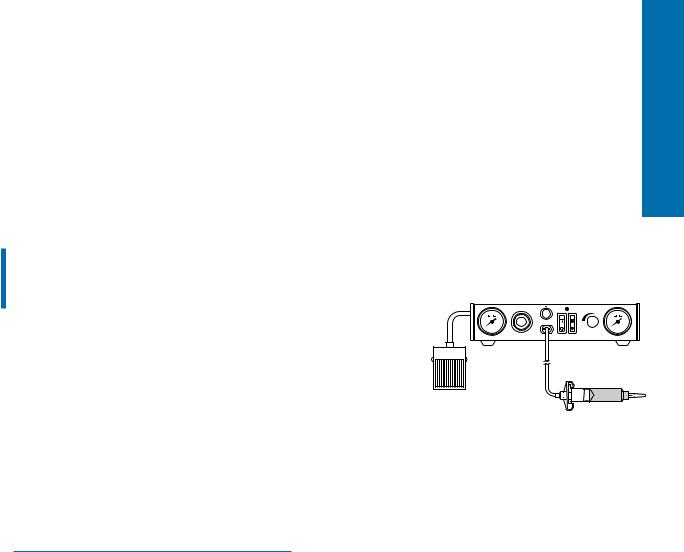
1000XL -- Hookup
Connect the air input hose to a plant air source. Set plant air supply within 80 to 100 psi (5.5 to 6.9 bar). Where required, use an EFD five-micron filter regulator #2000F755 (see Warranty).
Attach the air input hose coupling to the dispenser. Pull back metal ring to attach to dispenser.
Check the voltage label on the input voltage selector cartridge. To change the voltage, remove the voltage selector from the cartridge, rotate it and position the correct voltage to show through the cartridge window. Replace the cartridge into the power cord receptacle and insure that both sides snap securely into position.
Install the power cord.
Attach the 10cc barrel pre-filled with blue, nontoxic test fluid (included with the dispenser) to the 10cc adapter head.
Take the 10cc adapter assembly (#5150 on the adapter head) and insert the black, male quick-connect into the air output fitting on the front panel and turn clockwise to lock. Place the barrel in the barrel stand.
During the initial testing, you will not use the vacuum control. Keep this control shut off (turned completely clockwise—do not force).
Spare fuse
120 |
220 |
|
|
100 |
|
Voltage value
Cartridge window (check voltage indicated)
1000XL

CONTROLS and CONNECTIONS
|
|
Air pressure |
Time |
|
Barrel |
|
|
|
||||||
Air gauge |
regulator |
control |
|
vacuum control |
Vacuum gauge |
|||||||||
2 |
|
1 |
|
|
3 |
|
|
Cycle LED 4 |
|
|
|
5 |
|
|
|
|
|
|
|
|
|||||||||
|
|
|
|
|
|
|
|
|
|
|
|
|
|
|
|
|
|
|
|
|
|
|
|
|
|
|
|
|
|
|
|
|
|
|
|
|
|
|
|
|
|
|
|
|
|
|
|
|
|
|
|
|
|
|
|
|
|
|
|
|
6 |
7 |
Air output |
Power |
Timer |
quick-connect |
switch |
bypass |
|
Voltage selector and |
Cover screw |
fuse cartridge |
220
Vacuum transducer |
Air input |
Power input |
air exhaust port |
|
receptacle |
1000XL -- Setup for Testing
Power switch 6 should be off.
The amount of material dispensed each cycle depends on the combination of air pressure, time of air pulse, viscosity of material and dispensing tip size.
The first step is to remove the tip cap from the pre-filled barrel of blue test material (twist and pull). Replace it with an 18 gage (green) tapered dispensing tip. Press the tip on and twist clockwise to lock.
Pull out air pressure regulator knob 1 until it "clicks" into the unlocked position. Turn clockwise to adjust the air pressure to 30 psi (2.1 bar) for the initial tests.
Always set the pressure desired by turning the air regulator knob 1 clockwise. To reduce the pressure, turn the knob counterclockwise until the air gauge 2 reads a lower pressure than desired. Then increase and stop at desired pressure. Push knob in to lock.
Set the time control 3 to #7. Dispense cycle time increases from 0.01 second minimum to 1.0 second as knob is turned clockwise.
Be sure vacuum control 4 is shut off. In the initial tests, the vacuum pressure gauge 5 will indicate zero pressure. You may notice the needle on this gauge (when turned off) will jump slightly after each cycle. This is normal.
Press power switch 6 to turn on the dispenser. It will light green.
Press timer bypass switch 7. It will light yellow. In this operation mode, the timer will be bypassed to fill the dispensing tip before you begin testing. A continuous flow of material will occur as long as the foot pedal is pressed.
Please continue to page 14 for test procedures.
1000XL
Loading...