


Operating Guide
1500 Series Dispenser
1500XL • 1500XL-15 • 1500XL-CA • 1500DV-15 • 1500D
®
US & Canada: 800-556-3484 In the UK: 0800 585733 In Mexico: 001-800-556-3484
A NORDSON COMPANY
Introduction
The advanced 1500 Series dispensers provide years of trouble-free, productive service. This Operating Guide will help you maximize the usefulness of your new dispenser.
Please spend a few minutes to become familiar with the controls and features of your new dispenser. Follow our recommended testing procedures. Review the helpful information we have included based on over 30 years of industrial dispensing experience.
Most questions you will have are answered in this Guide. However, if you need assistance, please do not hesitate to contact EFD or your authorized EFD distributor.
US & Canada, call 800-556-3484.
In Mexico, call 001-800-556-3484.
In the UK, ring free 0800 585733.
The EFD Pledge
We pledge that you will be completely satisfied with our products. We endeavor to ensure that every EFD product is produced to our no-compromise quality standards.
If you feel that you are not receiving all the support you require, or if you have any questions or comments, I invite you to write or call me personally.
Our goal is to build not only the finest equipment and components, but also to build long-term customer relationships founded on superb quality, service, value and trust.
Peter Lambert, President
This manual is for the express and sole use of EFD dispenser purchasers and users, and no portion of this manual may be reproduced in any form.
EFD, ULTRA System, LV Barrier, SmoothFlow, ZeroDraft, SafetyLok, SnapLok and DispenStand are trademarks of EFD Inc. ©2006 EFD, Inc.
Contents
Getting Started ............................................................................. |
|
4 |
Specifications |
|
|
First Steps .................................................................................... |
|
5 |
Unpacking the Dispenser & Activating your Ten Year No-fault Warranty |
||
Microprocessor Control ............................................................. |
|
6-7 |
How to Use the Display and Control Pad |
|
|
1500XL - Setup & Use ................................................................. |
|
8 |
Hookup ............................. |
8-9 |
|
Setup for Testing .......... |
10-11 |
|
1500DV - Setup & Use ............................................................... |
|
12 |
Hookup ......................... |
12-13 |
|
Setup for Testing .......... |
14-15 |
|
1500D - Setup & Use ................................................................. |
|
16 |
Hookup ......................... |
16-17 |
|
Setup for Testing .......... |
18-19 |
|
Testing the Dispensers ......................................................... |
|
20-21 |
Making Timed Deposits of Medium to Thick Fluids |
|
|
Changing Deposit Size and Drawing Stripes |
|
|
Programming Deposit Size |
|
|
How to Use the Vacuum Control ........................................... |
22-23 |
|
Making Timed Deposits of Watery-thin Fluids |
|
|
ULTRA Dispensing System ................................................... |
|
24-25 |
Loading the Barrel Reservoirs ............................................... |
26-27 |
|
1500XL and 1500D Schematics & Parts .................................... |
28 |
|
1500DV Schematic & Parts ........................................................ |
|
29 |
How the 1500 Series Dispensers Work ..................................... |
30 |
|
Reordering Components ............................................................ |
|
31 |
Ten Year No-fault Warranty |
....................................................... |
32 |
Meets applicable CSA and CE requirements.
3

Getting Started
We have organized this Guide to provide setup and testing procedures for the 1500 Series dispensers.
If you have the 1500XL, 1500XL-15 or 1500XL-CA, first review pages 8 - 11 which illustrate how to hook up the dispenser and what the controls do.
For the 1500DV or 1500DV-15, review pages 12 - 15.
If you have the 1500D, review pages 16 - 19.
Next, pages 20 - 21 show how to dispense the thick paste-like test material included in the Test Kit. These instructions are common to the 1500XL, 1500DV and 1500D dispensers.
Finally, pages 22 - 23 illustrate how to dispense low viscosity fluid using the vacuum control. These instructions are common to the 1500XL, 1500XL-15, 1500XL-CA, 1500DV and 1500DV-15 dispensers.
The rest of the information in this Guide applies to all of the 1500 Series dispensers.
Specifications
Input Voltage: Selectable
100/120/220 VAC
50/60Hz
1500XL
1500XL-15 14/12VA 1500XL-CA
1500DV 18/15VA 1500DV-15
1500D 14/12VA
Internal Voltage: 24 VDC
Foot Pedal Voltage: 5.5 VDC
Cycle Rate: >600/minute
Time Control: microprocessor with
0.00005 second repeatability
Time Range: programmable
0.001 to 99.9 seconds
Initiation: momentary
Air Input: 80 to 100 psi (5.5 to 6.9 bar)
Air Output:
1500XL, 1500DV, 1500D
0 to 100 psi (0 to 6.9 bar)
1500XL-15, 1500XL-CA, 1500DV-15 0 to 15 psi (0 to 1.0 bar)
1500XL, 1500XL-15, 1500XL-CA
10⅜ x 8½ x 2⅝˝ |
4 lb 14 oz |
(26.4 x 21.6 x 6.7 cm) |
(2.21 kg) |
1500DV, 1500DV-15 |
|
10⅜ x 8½ x 2⅝˝ |
5 lb 2 oz |
(26.4 x 21.6 x 6.7 cm) |
(2.32 kg) |
1500D |
|
8⅝ x 8½ x 2⅝˝ |
4 lb 2 oz |
(21.9 x 21.6 x 6.7 cm) |
(1.87 kg) |
4

First Steps
First: Unpack and use the checklist enclosed with the Dispenser Kit to identify all items. If there is any discrepancy, please call us immediately.
Second: Power and compressed plant air should be available where the dispenser is to be set up. Air pressure should be between 80 and 100 psi (5.5 and 6.9 bar). If you are not using an EFD five-micron filter regulator #2000F755, be certain your plant air is properly filtered and dry and a regulated, constant air pressure is supplied to the dispenser.
Note: Model 15000XL-CA is supplied with an EFD five-micron filter regulator with coalescing filter (#2000F756).
Bottled nitrogen can be used.
Warning: If high pressure bottled air or nitrogen is used, a high pressure regulator must be installed on the bottle and set at 100 psi maximum. The 2000F755 filter regulator is not recommended.
Check the voltage label to be certain it is set to the available power.
Third: Now is a good time to ACTIVATE your extended Ten (10) Year No-fault Warranty. Please fill in and return the postage paid Warranty card. Or if you prefer, call the appropriate toll-free number listed below, provide the serial number of your dispenser and respond to a few short questions. You are then assured of complete protection for 10 years.
US & Canada, call 800-556-3484.
In Mexico, call 001-800-556-3484.
In the UK, ring free 0800 585733.
5
Microprocessor Control
Once your dispenser is set up, return to these pages to familiarize yourself with the various functions of the microprocessor controls.
Disconnect the male quick-connect on the barrel adapter hose from the dispenser before testing each function to prevent inadvertent fluid dispensing.
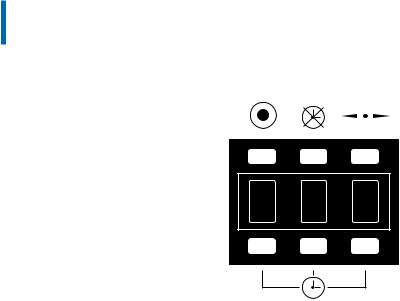
Program mode
Press to clear the display. Any decimals will disappear and the time range will reset to 000. Display alternates bright and dim to indicate the program mode.
Timer bypass mode
Press once and the display changes to - - - (dashes). Foot pedal now controls liquid flow. Press again and dashes are replaced by previously set time.
0. 2 5
Decimal button
Press to move decimal. When no decimal shows, time range is
.000 to .999 seconds.
Time set buttons
Each button sequentially controls the display digit in that panel. Each press advances the display 0.....9 and repeats.
6

How to Use the Display and Control Pad
0 5 0
.050 seconds
To change the displayed time
Start by setting the digits at zero. Press the  button twice to zero the display.
Press the button below each panel to set a specific time. Be sure the decimal is in the correct place for the time you require. (Cannot be done in program mode.)
0. 5 0
0.50 seconds
0 5. 0
5 seconds
Timer bypass mode (foot pedal control)
Press the  button, - - - (dashes) will appear. To get back in the time mode, press again. (This mode is used for filling the tip and making by-eye deposits. Cannot be done in program mode.)
Program mode
Press the  button once. Display flashes. Use the foot pedal to establish deposit size (and time). Press
  again, flashing stops and programmed time is displayed. Decimal will automatically move to appropriate position.
Change decimal position
Press the 

 button to move the decimal during manual time set. No decimal shows when time range is .000 to .999 seconds. (Cannot be done in program mode.)
To interrupt the dispense cycle
The foot pedal is pressed while dispensing. To interrupt dispensing in mid-cycle and reset to the original time display, press the pedal a second time.
7

Blue test
Plant air, 125 psi maximum to regulator. Output from regulator should be a minimum of 80 psi, maximum of 100 psi.
|
Air input |
hose |
Note: For hookup purposes, connections for the 1500XL, 1500XL-15 and 1500XL-CA models are identical.
Power cord
Check voltage label on dispenser
Foot pedal assembly
Male quick-connect, insert and twist to lock
8
1500XL -- Hookup
Connect the air input hose to a plant air source. Set plant air supply within 80 to 100 psi (5.5 to 6.9 bar). Where required, use an EFD five-micron filter regulator #2000F755 (see Warranty).
Attach the air input hose coupling to the dispenser. Pull back metal ring to attach to dispenser.
Plug in the polarized foot pedal connector.
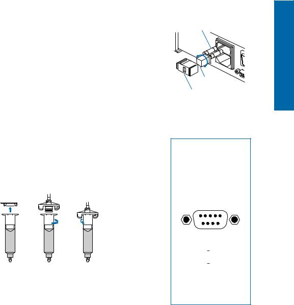
Check the voltage label on the input voltage selector cartridge. To change the voltage, remove the voltage selector from the cartridge, rotate it and position the correct voltage to show through the cartridge window. Replace the cartridge into the power cord receptacle and insure that both sides snap securely into position. Install the power cord.
Note: For 1500XL-15 and 1500XL-CA dispensers, use the test barrel filled with clear fluid and the red 25 gage tip. Refer to "Making Timed Deposits of Watery-thin Fluids" on page 22.
Attach the 10cc barrel prefilled with blue, nontoxic test fluid (included with the dispenser) to the 10cc adapter head.
Take the 10cc adapter assembly (#5150 on the adapter head) and insert the black, male quick-connect into the air output fitting on the front panel and turn clockwise to lock. Place the barrel in the barrel stand.
During the initial testing, you will not use the vacuum control. Keep this control shut off (turned completely clockwise—do not force).
Spare Fuse
120 |
220 |
|
001 |
||
|
Voltage Value
Cartridge Window (check voltage indicated)
Note: The dispenser is shipped with the fuse cartridge set for 120 VAC input.
I/O Connection
The 9 pin D connector and internal circuitry provides external initiate with end-of- cycle feedback. The pin connections are shown below. For complete schematic and detailed information, please contact EFD.
|
5 |
4 |
3 |
|
2 |
1 |
|
|
9 |
8 |
7 |
|
6 |
Pin |
Function |
|
|
|
||
1. |
Initiate + |
|
|
|
||
2. |
Initiate |
] 5-24 VDC |
||||
3. |
Output + |
|
|
5-24 VDC |
||
4. |
Output |
] |
|
250 mA Max |
||
5.Contact Closure
6.Chassis Ground
7.Contact Closure
8.Not Used
9.Not Used
Note: A 9-pin male connector assembly is available from
EFD (order part #7154).
1500XL
9
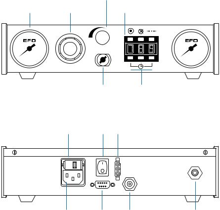
1500XL CONTROLS & CONNECTIONS
Note: The controls for the 1500XL, -15 and -CA models are identical.
Barrel vacuum control
Air gauge |
Air pressure |
|
regulator |
|
Air output quick-connect
Display and control pad
(Refer to pages 6-7 for detailed instructions.)
Time set buttons
Vacuum gauge

Voltage selector and |
Power |
Foot pedal |
fuse cartridge |
switch |
receptacle |
|
|
|
Blue |
|
Male quick-connect, |
test fluid |
|
insert and twist to lock |
Power input |
I/O 9 pin |
Vacuum transducer/ |
Air input |
receptacle |
interface |
air exhaust port |
|
|
connector |
|
|
10
 Loading...