

Page 1

Service Manual
Fuller Mid Range Transmissions
TRSM4106
October 2007
Page 2

For parts or service call us
Pro Gear & Transmission, Inc.
1 (877) 776-4600
(407) 872-1901
parts@eprogear.com
906 W. Gore St.
Orlando, FL 32805
Page 3

Page 4
Eaton 6-Speed Synchromesh Transmission
Truck Components Operations Europe
PO Box 11 Worsley
Manchester M28 5GJ
England
Service Manual
(4106 / 5206)
Page 5

Section 1 General
1/1 Letter and Model Designation
1/2 Technical Data
1/3 Lubrication
1/4 Recommended Lubricants
1/5 Torque Tightening Recommendations
1/7 Disassembly Precautions and Inspection of Expendable Parts
1/9 Reassembly Precautions
1/10 Gear End Floats
1/11 Special Tools
1/14 Locally Made Tools
Section 2 General Discription
2/1 Features
2/2 Gear Change Pattern
2/2 Power Flow Diagrams
Section 3 Shifting Controls
3/2 Remote Control - Exploded View
3/3 Remote Control Disassembly
3/4 Remote Control Reassembly
3/7 Direct Control - Exploded View
3/8 Direct Control Disassembly
3/9 Direct Control Reassembly
Section 4 Transmission Overhaul
4/2 Transmission Case - Exploded View
4/3 Transmission Case Disassembly
4/9 Layshaft Disassembly
4/10 Layshaft Reassembly
4/11 Synchroniser Flange Removal / Fitment
4/12 Maninshaft Disassembly (New Type)
4/13 Maninshaft Reassembly (New Type)
4/17 Mainshaft Assembly - Exploded View (NewType)
4/31 Mainshaft Disassembly (Old Type)
4/32 Mainshaft Assembly - Exploded View (Old Type)
4/35 Mainshaft Reassembly (Old Type)
4/41 Selector Shaft Disassembly
4/42 Selector Shaft Reassembly
4/44 Transmission Case Reassembly
5/01
Page 6

Section 2 General
5/01
Page 7

General
Model Designation
Example: FSO-4106A
FS Standard prefix
O Overdrive
4 Nominal torque in 00 lbs ft
1 Series 1
06 Number of forward gears
A Standard ratio set
B, C Alternative ratio sets
Transmission Identification
All transmissions are fitted with an identification plate on the left hand side of the front case showing
1. Transmission serial number.
2. Transmission model.
3. Manufacturing data code.
4. Transmission specification number.
The transmission specification number is unique to each customer and gives precise details of the transmission design level. This number must be quoted when ordering replacement parts.
There are currently two design levels of the 4106 transmission. Each level is identified by the specification number.
Y 0400
Y 04100
The middle digit denotes the design level.
1/1
5/01
Page 8

General
Technical Data
Models FS-4106A, FS-4106B, FS-5206A, FS(O)-5206B
Nominal Input Torque
FS-4106A
FS-4106B
FS-5206A
FS(O)-5206B
640 Nm
650 Nm
700 Nm
700 Nm
Weight 1)
Length 2)
Oil capacity
Vertical
Horizontal
Clutch Housing
Power Take-off Openings
PTO Drive Gears 3)
driven from the reverse idler gear at:
FS-4106A, FS-5206A
FS-4106B, FS-5206B
FS-4106B, FS(O)-5206B
driven from layshaft front gear at:
FS-4106A, FS-5206A
FS-4106B, FS-5206B
FS-4106B, FS(O)-5206B
115 kg
520 mm
7,5 lit
6,5 lit
SAE Standard
Left side (vertical installation), bottom right
(horizontal installation): 2 SAE 6 bolt facings
plus extended layshaft for Eaton PTO
Rotation to Engine
engine speed x
0,226 Same
0,271
0,336
engine speed x
0,434 Opposite
0,519
0,644
Gear
6
5
4
3
2
1
Reverse
1) including output coupling, low remote control; less clutch housing
2) front face of transmission case to rear face of output flange
3) recommended backlash is from 0.15 to 0.25mm.
FS-4106A
FS-5206A
1.00
__
1.38
__
2.00
__
3.10
__
5.25
__
9.03
__
8.07
%
Step
38
45
55
69
72
FS-4106B
FS-5206B
1.00
__
1.29
__
1.86
__
2.80
__
4.38
__
7.54
__
6.74
%
Step
26
43
50
57
72
FS(O)-4106B
FS(O)-5206B
1.00
__
1.37
__
2.12
__
3.56
__
6.08
__
9.03
__
5.43
%
Step
26
37
55
69
72
5/011/2
Page 9

General
Lubrication
Proper Oil Level
Before checking the oil level or refilling, vehicle should
be on level ground.
Make sure that the oil is level with the filler opening.
Draining Oil
Drain transmission while oil is warn. To drain oil remove
the drain plug at the bottom if case. Clean the drain plug
before re-installing.
Refilling
Clean area round filler plug.
Fill transmission to the level of the filler opening.
The exact amount of oil depends on the
transmission inclination. In every instance, fill to the
level of the filler opening. Do not overfill this causes
oil to be forced out of the case past the mainshaft and
input shaft seals.
Adding Oil
It is recommended that different types and brands of oil
are not intermixed because of possible incompatibility.
Operating Temprature
It is important that the transmission operating temperature does not exceed 120¡C (250¡F) for an extended
period of time. Operating temperatures above 120¡C
(250¡F) cause breakdown of the oil and shorten transmission life.
The following conditions in any combination can cause
operating temperatures of over 120¡C (250¡F):
1. Operating consistently at road speeds
under 32 km/h (20m.p.h.)
2. High engine RPM
3. High ambient temperature
4. Restricted air flow around transmission
5. Exhaust system too close to transmission
6. High horsepower, over-drive operation
7. High power PTO operation for
extensive periods while stationary
High operating temperatures may require more frequent
oil change.
Towing
When towing the vehicle, the propeller shaft between the
axle and transmission must be disconnected.
1/3
5/01
Page 10

General
Recommended Lubricants
Only use recommended lubricants to ensure smooth running.
Models Temprature RangeGrade
Mild EP Gear Oil
to Specification
MIL-L-2105 or
API-GL-4
Heavy Duty Engine Oil
to Specification
MIL-L-2104C or
MIL-L-46152 or
API-CD
DO NOT use oil additives, friction modifiers or synthetic lubricants.
SAE 80 W
SAE 90 W
SAE 80 W/90
SAE 50
SAE 40
SAE 30
Service Intervals
Lubrication Change and Inspection
Highway Use
First 5000 to 8000 km (3000 to
5000 miles)
Change transmission oil on new units
-26¡C to 21¡C
-12¡C to 37¡C
-26¡C to 38¡C
above -12¡C
above -12¡C
below -12¡C
Every 16000 km (10000 miles)*
Every 80000 km (50000 miles)+
Off Highway
First 30 hours
Every 40 hours *
Every 500 hours
Every 1000 hours +
Remove and clean oil strainer at each oil change.
Transmissions fitted with an oil cooler may additionally be fitted with a filter in the cooler line,
Renew the filter at every oil change.
* Or 2 months, whichever occurs first.
+ Or 12 months, whichever occurs first.
Inspect oil level. Check for leaks
Change transmission oil
Change transmission oil on new units
Inspect oil level. Check for leaks
Change transmission oil when severe dirt conditions exist
Change transmission oil (normal off- highway use)
5/011/4
Page 11
General
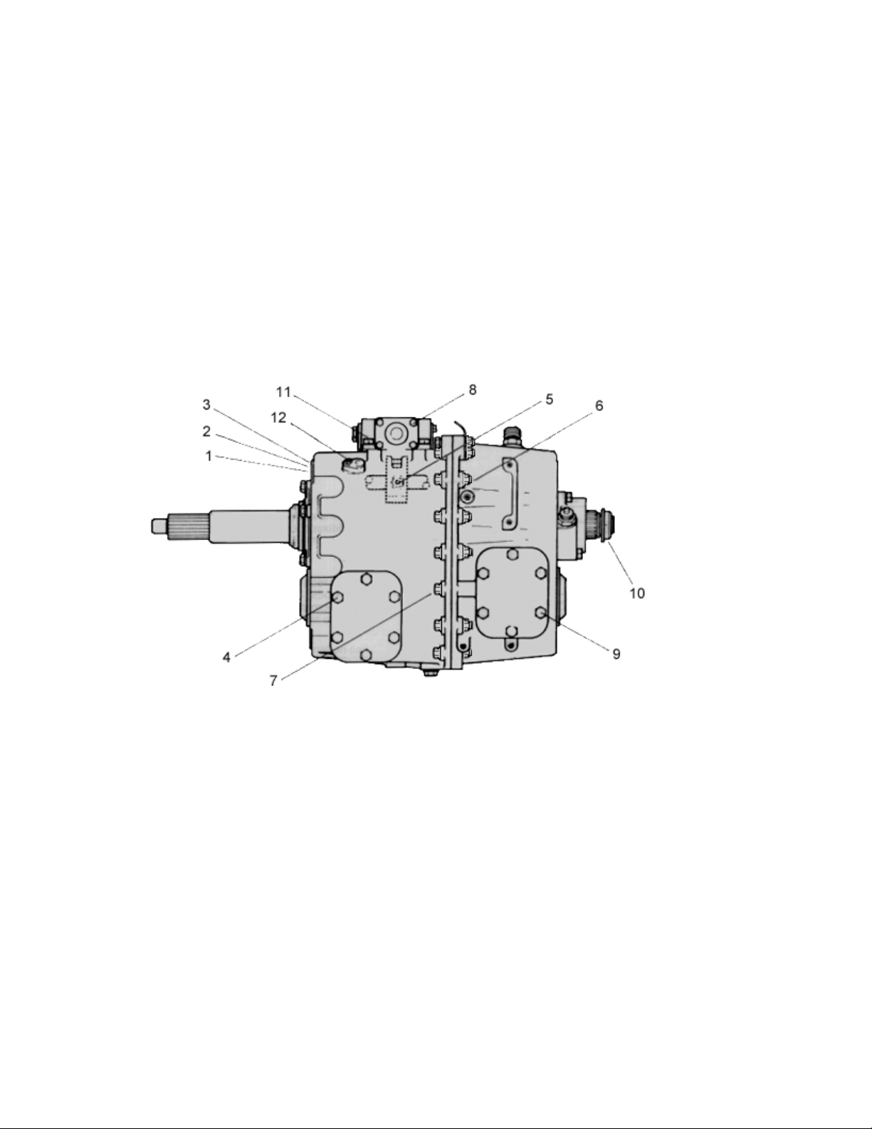
Torque Tightening Recommedations
Screws and Nuts
1. Clutch Housing
12 Studs M12 Thread 59 Nm (43 lbs ft) minimum. Installed with Loctite 242.
2. Clutch Housing
12 Nuts M12 Thread 69 to 78 Nm (51 to 58 lbs ft). With Plain Washers and Spring Lockwashers.
3. Clutch Housing
12 Capscrews M12 Thread 69 to 78 Nm (51 to 58 lbs ft). With Plain Washers and Spring
ockwashers.
4. Front P.T.O. Cover
6 Capscrews M10 Thread 35 to 39 Nm (25 to 29 lbs ft).
5. Selector Block Tapered Lockscrew
1 Lockscrew M10 Thread 35 to 39 Nm (25 to 29 lbs ft). Patchlock or Thread coated with Loctite 270.
6. Main Casing Halves
15 Capscrews with Plain Nuts M10 Thread 51 to 58 Nm (38 to 43 lbs ft). With Plain Washers
under Capscrews and Nuts.
15 Flange headed screws and Nuts M10 Thread 45 to 55 Nm.
7. Main Casing Halves
3 Capscrews M10 Thread 51 to 58 Nm (38 to 43 lbs ft). Plain Washers.
3 Flange headed screws M10 Thread 30 to 40 Nm.
8. Remote Control Housing End Cover
4 Capscrews M8 Thread 20 to 24 Nm (15 to 18 lbs ft). Spring Lockwashers.
9. P.T.O./Reverse Idler Gear Cover
6 Capscrews M10 Thread - 35 to 39 Nm (25 to 29 lbs ft).
10. Output Shaft
Locknut M33 Thread 490 to 588 Nm (362 to 434 lbs ft). With Nylon Locking Insert.
11. Remote Control Housing
4/6/8 Capscrews M10 Thread 35 to 39 Nm (25 to 29 lbs ft). Plain Washers and Spring Lockwashers.
12. Overdrive Selector fork Pivots
2 Capscrews M8 Thread (with lockwashers) 20 to 24 Nm (15 to 18 lbs ft).
1/5
5/01
Page 12

General
Torque Tightening Recommedations (continued)
Screws and Nuts
1. Remote Control Shaft Lever
1 Capscrew and Nut M10 Thread 35 to 39 Nm (25 to 29 lbs ft). With Spring Lockwasher.
2. Selector shaft Detent Cover
2 Capscrews M8 Thread 20 to 24 Nm (15 to 18 lbs ft). Spring Lockwashers.
3. Oil Filler Plug
M24 Thread 32 to 37 Nm (24 to 27 lbs ft).
4. Layshaft Front Bearing Cover
4 Capscrews M12 Thread 69 to 78 Nm (51 to 58 lbs ft). Spring Lockwashers.
5. Input Shaft Front Bearing Cover
5 Capscrews M10 Thread 35 to 39 Nm (25 to 29 lbs ft). Spring Lockwashers.
6. Remote Control Housing Detent Cover
2 Capscrews M8 Thread 20 to 24 Nm (15 to 18 lbs ft). Lockwashers.
7. Oil Drain Plug (Magnetic)
M24 Thread 32 to 37 Nm (24 to 27 lbs ft).
8. Speedo Pinion Adaptor
M22 Thread 20 to 27 Nm (15 to 20 lbs ft). Copper Washer.
9. Speedometer Housing
4 Capscrews M10 Thread 35 to 39 Nm (25 to 29 lbs ft). Plain Washers and Spring Lockwashers.
10. Layshaft Rear Bearing Cover (Rear P.T.O.)
4 Capscrews M12 Thread 69 to 78 Nm (51 to 58 lbs ft). Spring Lockwashers.
11. Reverse Lamp Switch
M16 Thread 16 to 22 Nm (12 to 17 lbs ft).
5/011/6
Page 13

General
Disassembly Precautions
It is assumed in the detailed disassembly instructions
that the lubricant has been drained and the necessary
linkage and air lines (if fitted) have been removed from
the chassis.
Removal of the gear shift remote control housing
assembly is included in the detailed instructions; however, this assembly may also be removed from the transmission before removing unit from vehicle.
Follow each procedure closely in each section, making
use of both the text and the pictures.
1. Bearings Carefully wash and relubricate all
bearings as removed and protectively wrap until ready
for use. Remove bearings with pullers designed for this
purpose.
2. Assemblies When disassembling the various
assemblies, such as the mainshaft, layshaft and remote
control housing, lay all parts on a clean bench in the
same sequence as removed. This procedure will simplify reassembly and reduce the possibility of losing parts.
When pulling off synchroniser hubs follow the procedures detailed in Disassembly using a suitable puller of
adequate capacity. Failure to adhere to the recommended procedures may cause irreparable damage.
3. Snap rings Remove snap rings with pliers
designed for this purpose. New selective fit snap rings
must be fitted as specified in Reassembly .
4. Cleanliness Provide a clean place to work.
It is important that no dirt or foreign material enters the
unit during repairs. The outside of the unit should be
carefully cleaned before starting the disassembly. Dirt is
abrasive and can damage bearings.
5. When Pressing Apply force to shafts, housings etc. with restraint. Movement of some parts is
restricted. Do not apply force after the part being driven
stops solidly. Use soft hammers for all disassembly
work.
Do not use pry bars or chisels to separate casing halves
and housings or irreparable damage may be caused.
Inspection of Expendable
Before reassembling the transmission, the individual
parts should be carefully checked to eliminate those
damaged. They should be renewed. This inspection
procedure should be carefully followed to ensure the
maximum wear life from the rebuilt unit.
The cost of a new part is generally a small fraction of
the total cost of downtime and labour, should the use of
a questionable part make additional repairs necessary
before the next regularly scheduled overhaul.
Recommended inspection procedures are set forth in
the following check list.
A. Bearings
1. Wash all bearings in clean solvent. Check rollers
and races for pits and spalled areas. Renew damaged
bearings.
2. Lubricate undamaged bearings and check for axial
and radial clearances. Renew bearings with excessive
clearances.
3. Check fits of bearings in housing bores. If outer
races turn too freely in the bores, the housing should be
renewed. Check housing bores for signs of wear prior
to taking this action. Only replace housing if wear is
seen as a result of bearing spin.
B. Gears
1. Check gear teeth for pitting of the tooth faces.
Gears with pitted teeth should be renewed. Check the
reverse gear dog engagement teeth for freedom from
damage.
2. Check the internal bearing surfaces for wear of the
effects of overheating.
3. Check axial clearances of gears. Where excessive
clearance is found, check gear and hub for excessive
wear.
Maintain the specified axial clearance on mainshaft forward gears.
C. Bearing Sleeve Mainshaft
1. Sleeves with groove formation, pits or which have
either been overheated or worn out must be renewed.
1/7
5/01
Page 14

General
Inspection of Expendable Parts
D. Synchroniser Assemblies
1. Check to ensure all splines are free from excessive
wear.
2. Check that the engagement dog teeth on the sliding
sleeves, synchroniser rings are free from chipping and
burring.
3. Check that the synchroniser ring cones are not
excessively worn or showing the effects of overheating.
Check the clearance between the synchroniser ring and
the synchroniser flange is between 1.9 mm maximum
and 0.5 mm minimum.
4. Renew the springs, plungers and rollers.
E. Splines
1. Check splines on all shafts for wear. If synchroniser
hubs, output drive flange or clutch hub have worn into
the sides of the splines, the shafts in this condition must
be renewed.
F. Thrust Washers
4. Check condition and fit of selector key and inter-
lock key in shift shaft. Worn or damaged keys must be
renewed.
J. Gear Shift Remove Control
1. Check spring tension on cross shaft. Renew ten-
sion springs if shaft moves too freely.
2. If housing is dismantled, check cross shaft and
inner lever and the bearing bushes for wear. Renew
worn parts.
3. Check all seals and locating journals. Renew worn
parts.
K. Bearing Covers
1. Check covers for wear from thrust. Renew covers
worn or grooved from thrust of bearing outer race.
2. Check bores of covers for wear. Renew those worn
oversize.
L. Oil Return Threads and Seals
1. Check surfaces of all thrust washers. Washers
scored or reduced in thickness should be renewed.
G. Reverse Idler Gear
1. Check bearings and shaft for wear from action of
roller bearings.
H. Clutch Release Parts
1. Check clutch release parts, yokes and bearing car-
rier. Check pedal shafts. Renew worn shafts and bearings.
I. Gear Selector Shaft Assembly
1. Check forks and keys for wear at contact points.
Renew worn parts.
2. Check forks for excessive and uneven wear, renew
worn forks.
3. Check lockscrew in selector block. A lockscrew with
worn taper must be renewed.
1. Check oil seal in front bearing cover for damage and
wear, renew if necessary.
2. Check oil seal in speedometer housing for damage or
wear, renew if necessary. Renew grit shield if worn or
loose on flange.
3. Check oil seal journals for wear and renew if worn or
grooved.
M. O-Rings
1. Renew all O-rings.
5/011/8
Page 15

General
Reassembly Precautions
Make sure that interiors of all housings are clean. It is
important that dirt be kept out of transmission during
reassembly. Dirt is abrasive and can damage polished
surfaces of bearings and washers. Use certain precautions, as listed below, during reassembly.
1. Gaskets Use new gaskets where detailed only
(neutral detent cover and remote control housing covers). All other locations ensure mating faces are clean
and undamaged and apply a continuous bead of Loctite
518 Flange Sealant to one face only. Do not apply
excessive sealant or allow it to penetrate into the bearings.
2. Capscrews Use thread sealant (Loctite 641) on
all capscrews. The corresponding torque ratings are to
be found in Torque Recommendations for Screws and
Nuts .
3. O Rings Lubricate all O rings lightly with silicone lubricant.
4. Initial Lubrication Lubricate bearings with
gearbox oil during reassembly.
9. Layshaft The layshaft gears are a shrink and
press fit on the layshaft body. The gears must be heated to 150¡C (300¡F) before assembly.
10. Prior to fitting a flange (or yoke) ensure that the
seal track is not grooved, scored or pitted. If in doubt, it
must be replaced.
11. All synchroniser flanges are now loctited to the
gears. It is recommended that this is carried out before
reassembly commences to allow sufficient time for the
Loctite to cure.
5. Axial Clearances Maintain the end float of
mainshaft gears as detailed in the chart on the following
page.
6. Bearings Use of flange-end bearing drivers is
recommended for the installation of bearings. These
drivers apply equal force to both races of the bearing,
preventing damage to balls and races and maintaining
correct bearing alignment with shaft and bore. A tubular
type driver, if used, will apply force only to the inner
race. Heating the bearing inner tracks will aid installation.
7. Output Shaft Drive Flange Tighten the nut to
the correct torque.
8. Synchroniser Hubs All synchroniser hubs are
an interference fit on the mainshaft splines and must be
heated to approximately 85¡C (180¡F) before installation.
1/9
5/01
Page 16

General
Gear End Floats All dimensions in mm
Gear
Low Limit
High Limit
Tolerance
0,31
0,53
0,22
4th5th (o,d. 6th)
0,35
0,48
0,13
3rd
0,35
0,48
0,13
2nd
0,35
0,48
0,13
1st
0,40
0,57
0,17
Reverse
Sliding
Gear
5/011/10
Page 17

General
Special Tools
Some illustrations show the use of specialised tools. These tools are recommended for disassembly
and reassembly of the transmission. They make repair easier, faster and prevent damage.
The following tools are available from SPX UK (Ltd) Tel : +44 (0)1327 704461
LC 105A Bearing remover.
E 105-4 Countershaft bearing remover.
E 108 Driver.
E 109 Driver.
E 109-5 Selector control seal and bush installer.
Use with E 109.
E 109-6 Countershaft bearing cup installer adaptor.
Use with E 109.
E 108-5 Replacer adaptor for auxiliary countershaft
bearing and input bearing.
Use with E 108.
E 108-6 Mainshaft rear seal replacer adaptor.
E 109-7 Input shaft seal installer adaptor.
E 109-8 Selector shaft bush installer adaptor.
Use with E 109.
1/11
5/01
Page 18

General
Special Tools (continued)
E 109-9 Selector shaft plug installer adaptor.
Use with E 109.
E 109-10 Driver extension.
Use with E 109.
E 109-11 Countershaft bearing cone installer.
Use with E 109.
E 116-2 Adaptor gear assembly lifting fixture.
Use with E 116A.
LC 113A Flange holding wrench.
MS 284 Slide hammer.
E 114 Rear mainshaft bearing pilot.
E 115 Flange holding adaptor plate
E 116A Gear assembly lifting fixture.
E 117 Reverse idler shaft retaining pin installer.
MS 284-1 Extractor set - bearing/bush.
5/011/12
Page 19

General
Special Tools (continued)
The following general purpose pullers are available from Sykes-Pickavant Ltd., or through their
Dealers.
Three Legged Puller - Series 1500 with Hydraulic
Ram
Locally Made Tools
The following illustration shows a suitable cradle
which can be used to stand the transmission ’on
end’ during ’Disassembly’ and ’Reassembly’. The
thickness of the block has been calculated to lift
the mainshaft the required distance during removal
and installation of the layshaft. If the height of the
cradle is increasing, the thickness of the block
should be increased by the same amount.
Puller Kit - Series 1500 with Hydraulic Ram
All dimensions in mm.
Mounting Plates - 2 off.
1/13
5/01
Page 20

General
Special Tools (continued)
Locally made tools
1. 1 off hole 1.5 inches diameter 16 threads per
inch Whitworth form to suit Sykes Picavant
hydraulic ram No 150 000.
2. 8 holes 11 mm diameter.
Tool for 4 point ball bearing removal.
5/011/14
Page 21

2
General
Special Tools for United States
Eaton 4106/5206
SPX # NEW UK # Description
J-45895 LC 105A Bearing Remover
J-45896 E 105-4 Countershaft bearing remover
J-45902 E 108 Driver
Replacer adaptor for auxiliary countershaft bearing and input
J-45897 E 108-5
J 39588 E 108-6 Mainshaft real seal replacer adaptor
J-8092 E 109 Driver
J 39592-1&
J-39587 E 109-6
J-39589 E 109-7 Input shaft seal installer adaptor
J-39585-2 E 109-8
J-39585-1 E 109-9 Selector shaft plug installer adaptor. Use with E109
J-21465-13 E 109-10 Driver extension
J-39586 E 109-11 Countershaft bearing cone installer. Use with E109
J-39590 E 114 Rear mainshaft bearing pilot
J-45899 E 115 Flange holding adaptor plate
J-39584 E 116A Gear assembly lifting fixture
J-39584 E 116-2 Adaptor gear assembly lifting fixture. Use with E116A
J-45898 LC 113A Flange holding wrench
MS284 MS 284 Slide hammer
J-39591 E 117 Reverse idler shaft retaining pin installer
J-45901 MS 284-1 Extractor set - bearing/bush
E 109-5
bearing
Selector control seal and bush installer. Use with E109
Countershaft bearing cup installer adaptor. Use with E109
Selector shaft bush installer adaptor. Use with E109
1/15 5/01
Page 22

Section 2 General
Description
5/01
Page 23

General Description
Features
The Eaton six-speed transmissions have six forward speeds and are part of a family of synchromesh
transmissions. They have a simple shift pattern using a unique single rail selector mechanism.
The transmissions may be mounted vertically or horizontally and in both positions the gear change
remote control may be to the right or the left.
1. Left-Hand Horizontal 3. Right-Hand Vertical
2. Left-Hand Vertical 4. Right-Hand Horizontal
The synchroniser assemblies are of the baulk ring type with the gear ring cones manufactured separately
from the gears. This allows the synchroniser rings and flanges to be renewed without the need to renew
the gears themselves. Reverse gear is engaged by sliding the reverse gear on the mainshaft into mesh
with a dog clutch ring splined to the mainshaft.
2/1
5/01
Page 24

General Description
Gear Change Pattern
Simple shift pattern with the mechanism biased
in neutral between 3rd and 4th gears.
1 2
3 4
5 6
R
Power Flow in the Gears - Direct Drive Top Gear Version
5/012/2
Page 25
Section 3 Shifting
Controls
6 Speed MK.4
3/1
5/01
Page 26

Shifting Controls
Remote Control - Exploded View
1. Grooved pin
2. Inner striking lever
3. Cross shaft
4. Plug or Neutral switch
5. Pin
6. Washer
7. Breather
8. Housing
9. Plug
10. Gasket
11. End cover
12. Spring washer M8
13. Screw M8
14. Bolt M10 x 50
15. Outer lever
16. Washer
17. Nut M10
18. Boot
19. Oil Seal
20. Bush
21. Reverse plunger
22. Reverse detent spring
23. Detent cover gasket
24. Detent cover
25. Spring washer M8
26. Screw M8
27. Bush
28. Circlip
29. Spring retainer
30. Spring
31. Spring (LH only)
32. Spring retainer
33. Circlip
5/013/2
Page 27

Remote Control Disassembly
1. Ensure neutral is selected and remove the control assembly from the transmission.
2. Remove the outer shift lever and rubber boot.
Remove the neutral switch and pin (if fitted).
Note: The position of the lever is marked on the
shaft. Check before removal.
4. Remove the four separate capscrews and lift off
the end cover.
5. Remove the circlip from the shaft and remove
the spring retainer.
3. Remove the reverse detent cover and pull out
the spring and plunger.
6. Withdraw the booster spring, bias, spring inner
retainer and circlip.
3/3
5/01
Page 28

Remote Control Reassembly
7. Invert the housing and carefully drift out the
expansion plug.
8. Invert the housing, align the grooved pin in the
lever with the expansion plug hole.
1. If necessary renew the bearing bushes in the
housing using the special tool. The new bushes
are prefinished to the correct size.
2. If necessary renew the oil seal.
9. Drift out the pin. Remove the shaft and inner
lever.
3. Install the inner lever, long plain groove toward
the front of the housing.
5/013/4
Page 29

4. Install the shaft from the right hand side of the
housing.
7. Insert the springs and outer retainer.
Note: right hand drive units use a large
retainer: left hand drive units use one large (outer)
and one small (inner).
5. Align the inner lever on the shaft and install a
new grooved pin.
Note: Inner lever should be supported whilst driving pin to prevent damage to bushes.
6. Fit the inner circlip onto the shaft. Install the
smaller spring retainer.
8. Fit the outer circlip onto the shaft.
9. Fit a new gasket and secure the end cover to
the housing. Tighten to correct torque (20 to 24
Nm).
Note: The word Top has been cast into the cover
to identify correct positioning.
3/5
5/01
Page 30

10. Install the reverse detent plunger and spring
and fit the cover using a new gasket. Tighten the
capscrews to the correct torque (20 to 24 Nm).
11. Fit the rubber boot onto the housing. Align the
outer lever with the timing mark on the shaft. Fit
the pinch bolt and tighten to 35 to 39 Nm.
13. Apply Loctite 5900 sealant.
Fit control assembly to the transmission housing.
12. Fit the breather. Install the pin and neutral
switch (15 to 22 Nm). Apply sealant and install a
new blanking plug.
5/013/6
Page 31

Shifting Controls
Direct Control - Exploded View
Item
01 Housing
02 Bush
03 End cap
04 Spring washer
05 Screw
06 Breather
07 Plunger
08 Spring compression
09 Spring compression
10 Cover
11 Spring washer
12 Screw
13 Plunger
14 Spring
15 Cover
Item
16 Spring washer
17 Screw
18 Gaiter
19 Pin
20 Washer
21 Plug
22 End cap
23 Spring washer
24 Screw
25 Bush
29 Seating
30 Gear lever
31 Seating
32 Spring
33 Spring
34 Yoke
3/7
5/01
Page 32

Disassembly
1. Remove the rubber gaiter and breather.
2. Remove the screws, washers, detent cover
plate, spring and plunger.
4. Remove the screws, washers and end covers
from both sides of the housing.
5. If necessary the bushes in the end covers can
be replaced.
3. Remove the screws, washers, detent cover
plate, spring(s) and plunger.
6. Invert the housing and withdraw the yoke.
3/8
5/01
Page 33

Assembly
7. Remove the Circlip and spring.
8. Remove the seat and selector shaft.
1. Clean all joint faces. Fit the seat ensuring that
the slot aligns with the hole in the housing for the
pin.
2. Apply grease to the seat and then fit the pin.
9. Remove the pin and seat.
3. Apply a coating of grease to the Selector shaft
and then, ensuring that the slot in the selector shaft
aligns with the pin in the housing, fit the selector
shaft.
3/9
5/01
Page 34

4. Fit the seat ensuring that the slot in the seat
locates onto the pin and into the bore of the housing.
7. Apply a light coating of grease to the bushes in
the end covers. Apply Loctite 5900 to the joint
faces. Fit the end caps, screws and washers.
Torque screws to 20 to 24 Nm.
5. Ensuring that the smaller diameter of the spring
sits against the seat refit the spring and retaining
Circlip.
6. Install the yoke into the housing.
8. Refit the plunger, spring(s), end cover (apply
Loctite 5900 to the joint faces), screws and washers. Torque screws to 20 to 24Nm.
9. Refit the plunger, spring, detent cover (apply a
coating of Loctite 5900), screws and washers.
Torque screws to 20 to 24 Nm.
3/10
5/01
Page 35

10. Refit the rubber gaiter and breather.
3/11
5/01
Page 36

Section 4 Transmission
Overhaul
5/014/1
Page 37

Transmission Case
Exploded View
1. Screw M12
2. Washer M12
3. Cover
4. Washer
5. Screw M8
6. Rotation pins, overdrive
7. Front casing
8. Washer
9. Oil filler plug
10. Core plug
11. Neutral detent assembly
12. Screw
13. Spring washer
14. Cover
15. Gasket
16. Detent spring
17. Neutral detent plunger
18. Screw
19. Spring washer
20. Washer
21. Dowel
22. Bolt M10
23. Washer M10
24. Nut M10
25. Bushing
26. Oil trough
27. Hammer drive screw
28. Oil trough
29. Hammer drive screw
30. Dowel
31. Bushing
32. Reverse light switch or plug
33. Core plug
34. Rear casing
35. Screw M12
36. Spring washer M12
37. Cover
38. Cup plug
39. Cover
40. Spring washer
41. Screw M10
42. Gasket
43. Washer M10
44. Screw M10
45. Cover
46. Washer M10
47. Screw M10
48. Gasket
49. Magnetic drain plug
50. Washer
51. O ring
5/014/2
Page 38

Disassembly of Transmission Case
Caution: Drain gear oil from the transmission and
clean and refit the drain and filler plugs.
Note: The transmission illustrated in this section is
a standard ratio horizontally installed unit. The procedure is the same for all transmissions but the
physical size and number of teeth on some of the
gears will vary from those illustrated on overdrive
and alternative ratio models.
Horizontally installed units have the remote control
on the side of the transmission and alternative filler
and drain plug positions.
1. Secure the adaptor plates to the transmission
case rear mounting flanges.
Note: This may be a 4-hole square pattern on
early models.
2. Raise the transmission on a hoist and install the
unit onto the stand
4. Remove the reverse lamp switch.
5. Using a flange/yoke holding wrench remove the
output drive flange/yoke retaining nut.
3. Remove the speedometer pinion and adaptor or
electronic sender unit.
6. Remove the output drive flange/yoke, using a
suitable puller if necessary. Do not use a hammer
or the flange/yoke may be damaged.
4/3
5/01
Page 39

7. Ensure neutral is engaged and remove the
remote control housing bolts. Use a soft faced mallet to separate the housing from the transmission.
10 Position the transmission forward end uppermost on the stand or wooden cradle and remove
the detent spring cover plate, spring and plunger
as above or detent assembly (see below).
32mm
8. Measure the diameter of the core plug as shown.
If the diameter is 32mm then the retaining pin must
be removed as explained below. If the core plug
diameter is 37mm then a retaining pin is not fitted
therefore the following procedure can be missed
37mm
11.
9. Remove the rear PTO cover. Using the special
tool or an 8 mm punch, drive the reverse idler shaft
grooved pin INWARDS until the end is approximately 12 mm below the face of the hole. Do not
allow the pin to ’bottom’ against the shaft bore.
5/014/4
Page 40

12. Rotate the gear selector shaft to the left (vertically mounted) or right (horizontally mounted) so
that the case will not foul the selector block on
removal.
15. Remove the capscrews securing the input shaft
cover and remove the cover.
13. On overdrive models, remove the capscrews
retaining the two overdrive fork pivot pins and
remove the pins.
14. Remove the half case flange capscrews and
nuts. Note the position of the shorter capscrews
threaded into the case.
16. Remove the outer circlip from the input shaft
bearing.
17. Remove the spacer and bearing thrust washer.
4/5
5/01
Page 41

18. Using a soft face mallet break the seal and separate the front case from the rear case. DO NOT USE
PRY BARS OR CHISELS. Lift off the front case, leaving the input shaft and bearing in place.
20. Using a suitable long drift drive out the reverse
idler shaft and expansion plug from the case.
19. On overdrive models disengage and remove
the overdrive fork and pads.
1. Thrust washer
2. Needle roller bearing
3. Spacer
4. Reverse idler gear
5. Thrust washer
6. Reverse idler shaft - old design
7. Pin
8. ’O’ ring
9. Reverse idler shaft - new design
21. Remove the reverse idler gear and the thrust
washers. Remove the bearings and spacer from
the gear and the ’O’ ring from the reverse idler
shaft (old design).
22. Assemble the special lifting tool to the mainshaft under the 5th/6th synchroniser. Raise the
shaft by approximately 20 mm. This allows the
layshaft to lift clear.
5/014/6
Page 42

23. Lift out the layshaft
24. Lift off the input shaft with 6th gear flange.
Remove the 6th gear synchroniser ring.
26. Invert the rear case on the stand and remove
the capscrews securing the speedometer housing.
Note the positions of the different length capscrews. Remove the housing. If necessary drift out
the oil seal.
27. Remove the speedometer drive gear or tachograph rotor and the bearing spacer from the rear
case half.
25. Raise the hoist and lift out the mainshaft and
selector shaft and forks as an assembly. Carefully
lower on to a clean bench and remove the special
tool. Separate the selector shaft and forks from the
mainshaft.
28. Invert the casing on the stand and using the
special tool drift out the mainshaft rear bearing. Do
not allow the bearing to fall to the floor.
4/7
5/01
Page 43

29. Invert the casing on the stand and remove the
layshaft rear bearing cover and bearing spacer.
32. Drift out the layshaft front bearing cup using the
special tool. Remove the input shaft bearing using
the special tool.
30. Drift out the layshaft rear bearing outer cup
using the special tool.
31. Remove the layshaft front bearing retaining
plate and graded spacer from the front case.
33. If necessary, to renew the selector shaft bushes, drive the selector shaft expamsion plugs outwards from the case halves.
34. Invert the case halves and using the special
tool or a suitable (25mm diameter) mandrel drive
the selector shaft bushes out of the cases.
5/014/8
Page 44

Layshaft Disassembly
1. Support the shaft assembly and remove the
graded circlip retaining the front taper roller bearing.
2. Using the special tool remove the bearing cone
and roller assembly.
1. Countershaft assembly
2. Taper roller bearing
3. Distance piece
4. Taper roller bearing
5. Circlip
6. Shim
7. Spacer
3. Invert the shaft and remove the rear taper roller
bearing.
Layshaft Assembly
5/014/9
Page 45

Layshaft Reassembly
1. Heat the layshaft taper roller bearing inner races
to 85¡¡C (180¡F). Support the shaft assembly forward end uppermost and place the heated inner
cone and roller assembly onto the shaft. Use a
suitable mandrel to make sure bearing is fully
home.
2. From the range of graded fit circlips, select the
circlip which fits into the groove with the minimum
free play.
3. Fit the circlip using circlip pliers.
4. Invert the layshaft assembly and fit the heated
rear taper roller bearing inner race onto the shaft.
Make sure the bearing is fully home using a suitable mandrel.
Circlips are available in the following sizes and Part
Numbers.
Part No. Thickness (mm)
8870370 2,12
8870371 2,07
8870372 2,02
8871536 1,97
8871537 1,92
8871538 1,87
8871539 1,82
8871540 1,77
4/10
5/01
Page 46

Synchroniser Flange Removal / Fitment
Disassembly Assembly
1. Heat the gear and flange assembly to 80¡C to
deactiveate the Loctite. Using a suitable press or
puller, remove the flange from the gear.
Note: This also applies to the 6th gear flange on
the input shaft.
1. Using a suitable solvent ensure that both parts
are clean and free from oil.
2. Apply a thin bead of Loctite 648 to the spine
teeth of the gear. Press on the synchroniser flange
ensure the flange is fully home. Wipe off any
excess.
3. Allow the parts to cure for a minimum of two
hours.
Note: If the flange does not seat squarely, the procedure should be repeated.
5/014/11
Page 47

Mainshaft Assembly
Mainshaft Disassembly
Eaton have recently introduced a new design of
mainshaft assembly. As both designs are currently
in use strip and rebuid procedures for both are
included in this manual
Note: All snap rings and circlips on the mainshaft
are graded for selective fit. Take care not to score
the bearing surfaces of the mainshaft when removing or fitting the snap rings or circlips.
Note: The end float of the gears on the mainshaft
is established in manufacture by machining the
components to fine tolerances. Before disassembly
of the mainshaft the end floats should be checked
to ascertain whether they are within
the recommended limits.
Where end float is found to be excessive it is necessary to check the gears, mainshaft, synchroniser
hubs and bearing sleeve for wear.
See Inspection of expendable parts and renew
where necessary.
End float check
Refer to picture above:
if the profile of the 1st/2nd gear synchroniser
sleeve is as shown above then the following procedure should be followed(new design).
Where the old design mainshaft is fitted refer to the
procedure from page 4/31 onwards.
1. End float may be checked with the mainshaft
assembled by using a dial gauge, as shown, or
feeler gauges. Mount the mainshaft assembly on a
suitable stand. Locate the dial gauge on the gear
and zero the gauge. Raise the gear and record the
reading.
Gear FS-5th 4th 3rd 2nd 1st
FSO-6th
Minimum 0,31 0,35 0,35 0,35 0,40
Maximum 0,53 0,48 0,48 0,48 0,57
Tolerance 0,22 0,13 0,13 0,13 0,17
All dimensions in mm.
Note: Reverse gear is a sliding gear.
4/12
5/01
Page 48

Exploded View
1. Mainshaft.
2. 3rd gear needle roller bearing.
3. 3rd speed gear.
4. 3rd gear synchroniser ring.
4a. 3rd gear synchroniser flange
5. Roller.
6. Plunger
7. Spring
8. 3rd/4th speed synchroniser hub
9. 3rd/4th speed synchroniser sleeve
10. 4th gear synchroniser flange
10a. 4th gear synchroniser ring
11. 4th gear
12. 4th gear needle roller bearing
13. 4th gear sleeve
14. Snap ring
15. 5th gear needle roller bearing (FS)
6th gear needle roller bearing (FSO)
16. 5th speed gear (FS)
6th speed gear (FSO)
17. 5th gear synchroniser ring (FS)
6th gear synchroniser ring (FSO)
17a. 5th gear synchroniser flange (FS)
6th gear synchroniser flange (FSO)
18. Roller
19. Plunger
20. Spring
21. 5th/6th gear synchroniser hub
22. 5th/6th gear synchroniser sleeve
5th gear synchroniser ring (FSO)
24. Circlip
25. 6th gear needle roller bearing (FS)
5th gear needle roller bearing (FSO)
26. 2nd gear needle roller bearing
27. 2nd gear
28. Synchroniser flange
29. Synchroniser inner ring
30. Synchroniser friction ring
31. Synchroniser ring
32. 1st/2nd gear synchroniser hub
33. Retainer
34. Spring
35. Ball
36. Detent poppet
37. 1st/2nd speed synchroniser sleeve
38. Circlip
39. 1st speed gear
40. 1st gear needle roller bearing
41. Reverse gear hub
42. Snap ring
43. Reverse gear needle roller bearing
44. Reverse gear
45. Mainshaft bearing
46. Tachograph
47. Dust shield
48. Coupling flange
49. Nut
4/13
5/01
Page 49

Disassembly
1. Mount the mainshaft assembly, plain end uppermost, in a soft jawed vice. Remove the synchroniser ring. Carefully slide the 5th/6th synchroniser
sleeve upwards until the three rollers are clear of
the groove in the synchroniser sleeve. Remove the
three rollers, the synchroniser sleeve, the three
plungers and three springs from the synchroniser
hub.
3. Invert the mainshaft assembly. Using a press or
suitable puller remove the mainshaft bearing inner,
reverse gear and reverse gear needle roller bearing.
2. Remove the 5th/6th-gear synchroniser hub
retaining Circlip.
4. Remove the reverse gear fixed hub retaining
snap ring.
5. Using a press or suitable puller remove the
reverse gear fixed hub and 1st speed gear.
4/14
5/01
Page 50

6. Remove the 1st speed gear needle roller bearing.
9. Using a press or suitable tool remove the synchroniser assembly and 2nd speed gear. Remove
the needle roller bearing.
7. Remove the synchroniser assembly retaining
Circlip.
8. To prevent the synchroniser assembly from separating during removal fit the retaining tool. The
tool fits onto the mainshaft, boss down, with the
three retainers located underneath 2nd speed gear.
Adjust the retainers so that there is no free play
between 2nd speed gear and synchroniser assembly.
Note: Should the synchroniser separate then refer
to the relevant section for assembly instructions.
10. Carefully remove the retaining tool and then
place the synchroniser assembly and 2nd speed
gear onto a suitable work surface. Remove 2nd
speed gear.
11. Invert the mainshaft. As the 5th /6th -gear synchroniser hub is not symmetrical identify its orientation. Using a press, or suitable puller, remove the
5th /6th -gear synchroniser hub, synchroniser ring
and 5th speed gear assembly. Note: Care must be
taken to ensure that damage to the teeth on the
synchroniser flange does not occur. (On an overdrive transmission it may be necessary to engage
the press/puller also over the gear).
5/014/15
Page 51

12. Remove the 5th gear needle roller bearing. (On
overdrive transmissions this will be 6th gear).
13. Carefully remove the 4th gear-bearing sleeve
retaining snap ring.
15. Place the assembly on to a suitable work surface, 4th speed gear, uppermost. Remove the
bearing sleeve, needle roller bearing and 4th gear
assembly
14. Using a suitable press or puller support the
mainshaft assembly underneath 3rd speed gear.
Note: It is imperative that the flange, which is part
of the mainshaft, does not foul the press or puller
legs as this may result in damage to the mainshaft.
Press or pull the 4th speed gear bearing sleeve,
4th speed needle roller bearing, 4th speed gear
assembly, 3rd /4th -speed synchroniser assembly
and 3rd speed gear assembly off. Remove the 3rd
speed gear needle roller bearing from the mainshaft.
16. Dismantle the 3rd /4th -speed synchroniser
assembly as previously described in paragraph
one.
17. Lift off the synchroniser hub and synchroniser
ring.
4/16
5/01
Page 52

Mainshaft Reassembly
Before assembling the synchroniser assemblies on to the mainshaft, check the fit of each
synchroniser ring to the relevant synchroniser
flange.
Procedure for 3rd , 4th , 5th and 6th speed
synchronisers.
Procedure for 1st and 2nd speed
Synchronisers
Note: The synchroniser flanges, apart from those
fitted to the 1st and 2nd speed gears, must be loctited to the gears.
a) Stand the synchroniser assembly on to a flat
surface (Either way up)
Place the synchroniser ring to the relevant flange
and while holding the two parts firmly together,
measure the clearance between the two component parts using feeler gauges at several points
around the circumference as shown. The clearance
should be between 0,5 and 1,9 mm. Renew both
parts if the measurement is not within the specified
limits. Retain the synchroniser rings and flanges in
their respective pairs for assembly in the same relative position.
b) Remove the synchroniser flange.
c) Place the synchroniser flange, spigot uppermost
onto the bench.
4/17
5/01
Page 53

d) Remove the synchroniser inner ring.
e) Fit the synchroniser inner ring, tangs uppermost,
on to the synchroniser flange.
g) Fit the synchroniser friction ring on to the synchroniser flange ensuring that the tabs on the synchroniser friction ring locate into the slots on the
synchroniser flange.
h) Remove the synchroniser ring.
f) Remove the synchroniser friction ring.
i) Fit the synchroniser ring onto the assembly.
4/18
5/01
Page 54

j) While holding the parts firmly together, measure
the clearance between the synchroniser ring and
synchroniser flange using feeler gauges at several
points around the circumference as shown. The
clearance should be between 0,5 and 1,9 mm. If
the measured dimension is outside these tolerances then the synchroniser assembly must be
changed.
Reassembly
Note: The synchroniser flanges, apart from those
fitted to the 1st and 2nd speed gears, must be loctited to the gears.
1. Place the retaining tool, boss uppermost, on to a
suitable surface.
k) Refer to paragraphs twelve to fifteen of the
assembly procedure in the section 1st /2nd speed
synchroniser assembly .
l) Invert the synchroniser assembly and repeat the
process.
2. Place the 1st /2nd speed synchroniser assembly
onto the retaining tool ensuring that the chamfer on
the synchroniser sleeve is uppermost.
3. Heat the assembly to 85¡ Centigrade and then
place the retaining tool and synchroniser assembly
onto the press table.
4/19
5/01
Page 55

4. Fit the 2nd speed gear to the synchroniser
assembly ensuring that the splines on the gear
engage into the splines on the synchroniser
assembly. Fit and lubricate the needle roller bearing.
6. To prevent the synchroniser assembly separating the retainers should be used. Adjust the retainers so that there is no free play between 2nd
speed gear and the synchroniser assembly.
5. Fit the mainshaft, plain end uppermost, into the
2nd speed gear and synchroniser assembly ensuring that the splines on the mainshaft engage into
the splines of the synchroniser assembly. Press the
mainshaft into the synchroniser assembly.
7. Lubricate and install the 3rd gear needle roller
bearing and 3rd gear assembly.
5/014/20
Page 56

8. Lubricate the 3rd gear synchroniser flange and
then fit the synchroniser ring.
9. Heat the 3rd /4th -gear synchroniser hub to 85¡
Centigrade. Fit the synchroniser hub over the
splines on the mainshaft ensuring that the large
slots in the synchroniser hub align with the large
shoulders on the synchroniser ring. Press the synchroniser fully home.
11. Assemble the three springs and plungers into
the synchroniser hub. Place the synchroniser
sleeve over the synchroniser hub and support it
with the internal groove just above the synchroniser hub. Position the three rollers as shown, resting
on the heads of the plungers, and press downward
on the synchroniser sleeve. This compress the
springs allowing the synchroniser sleeve to centralise in the neutral position.
12. Place the 4th gear synchroniser ring onto the
synchroniser assembly ensuring that the shoulders
on the synchroniser ring locate into the slots of the
synchroniser hub. Lubricate the synchroniser ring.
10. Check that the 3rd gear end float is within the
tolerance stated in the chart.
13. Fit the 4th speed gear assembly. Lubricate the
needle roller bearing and then install it into the
gear.
4/21
5/01
Page 57

14. Heat the 4th speed gear-bearing sleeve to 85¡
Centigrade and locate it onto the mainshaft and
inside the needle roller bearing. Press the bearing
sleeve into position.
15. Fit a new snap ring into the mainshaft groove
taking care not to damage the mainshaft-bearing
surface.
17. Fit the 5th speed gear assembly. Lubricate the
needle roller bearing and then install it into the
gear.
18. Lubricate the 5th gear synchroniser flange. Fit
the synchroniser ring.
16. Check that the 4th gear end float is within the
tolerance stated in the chart.
19. Heat the 5th /6th -speed synchroniser hub to
85¡ Centigrade and then install it, boss downwards,
onto the mainshaft. Ensure that the large slots on
the synchroniser hub align with the large shoulders
on the synchroniser ring. Press the synchroniser
hub until it is fully seated.
5/014/22
Page 58

20. From the range of graded circlips select the
one which fits into the mainshaft groove with the
least amount of free play. Fit the Circlip into the
groove.
21. Using feeler gauges check that the 5th gear
end float is within the tolerance stated in the chart.
22. Invert the mainshaft and then remove the
retaining tool.
23. Install the Circlip into the groove of the mainshaft. Take care not to damage the mainshaft bearing surface.
4/23
5/01
Page 59

24. Check that the 2nd speed gear end float is
within the tolerances stated in the chart.
25. Fit and lubricate the needle roller bearing. Fit
the 1st speed gear ensuring that the splines on the
1st speed gear engage into the splines of the synchroniser flange.
27. From the range of graded circlips select the
one which fits into the mainshaft groove with the
least amount of free play. Fit the Circlip into the
groove taking care not to damage the mainshaft
needle roller bearing surface.
28. Check that the 1st speed gear is within the
specified tolerance stated in the chart.
26. Heat the reverse gear hub to 85¡ Centigrade
and then, with the boss uppermost, fit it onto the
splines of the mainshaft. Press the reverse gear
hub until it is fully seated.
29. Fit the reverse gear needle roller bearing.
Lubricate the bearing and then fit the reverse gear,
boss down, onto the mainshaft.
4/24
5/01
Page 60

30. Heat the mainshaft bearing inner to 85¡
Centigrade and then fit it, shoulder down, onto the
mainshaft. Use a press, if necessary, to ensure that
the bearing is fully home against the shoulder.
1st /2nd speed Synchroniser
assembly.
Note: The synchroniser is supplied as an assem-
bly. Parts that are used to make the complete
assembly are not available separately.
1. Stand the synchroniser assembly on a flat surface with the spigot of the synchroniser sleeve
uppermost.
31. Invert the mainshaft. Assemble the three
springs and plungers into the synchroniser hub and
then install the synchroniser sleeve and rollers as
described in paragraph eleven.
32. Fit the synchroniser ring ensuring that the three
bosses on the synchroniser ring locate into the
three slots on the synchroniser hub. Lubricate the
synchroniser ring.
2. Push the synchroniser sleeve downwards.
3. Remove the synchroniser flange.
5/014/25
Page 61

4. Remove the synchroniser inner ring.
7. Remove the three retainers.
5. Remove the synchroniser friction ring.
6. Remove the synchroniser ring.
8. Taking care not to lose the balls or springs lift
the detent poppets to release the balls. Once the
balls have been removed it is possible to remove
the detent poppets and springs.
9. Remove the synchroniser sleeve.
4/26
5/01
Page 62

10. If not already removed at step eight remove the
detent poppets and springs.
13. Remove the synchroniser friction ring.
11. Remove the synchroniser hub.
12. Remove the synchroniser ring.
14. Remove the synchroniser inner ring.
5/014/27
Page 63

Assembly
1. Place the synchroniser flange, spigot uppermost
onto the bench.
4. Fit the synchroniser ring ensuring that the undercuts (1) line up with the tabs (2) of the synchroniser inner ring and that bosses (3) of the synchroniser ring are to the left hand side of tabs (2) of the
synchroniser inner ring as shown.
2. Fit the synchroniser inner ring, tangs uppermost,
on to the synchroniser flange.
3. Lubricate all surfaces of the synchroniser friction
ring. Fit the synchroniser friction ring ensuring that
the tabs locate in to the slots of the synchroniser
flange.
5. With the holes in the synchroniser hub uppermost.
6. Fit the synchroniser hub ensuring that the narrow slots are in line with the bosses of the synchroniser ring.
4/28
5/01
Page 64

7. Place the three retainers in the large recesses of
the synchroniser hub so that the legs of the blocks
engage with the tabs of the synchroniser inner ring
and the undercuts of the synchroniser ring.
8. Take the synchroniser sliding sleeve, stepped
side uppermost, and fit it on to the synchroniser
hub ensuring that the three internal bosses of the
synchroniser sleeve locate in the slots of the synchroniser hub.
10. Place the detent ball onto the spring and then
using a suitable tool push against the detent ball to
compress the spring.
11. Whilst the spring is compressed push the
detent poppet downwards into the synchroniser
hub until the ball engages with the annular groove
of the sleeve. Fit the remaining detent springs,
balls and plungers into position.
9. Place the detent poppets and springs into the
holes of the synchroniser hub.
12. Place the synchroniser ring on to the synchroniser hub so that the three bosses engage with the
three narrow slots on the synchroniser hub.
5/014/29
Page 65

13. Lubricate all surfaces of the synchroniser friction ring. Place the synchroniser friction ring, tabs
uppermost, on to the synchroniser hub.
14. Place the synchroniser inner ring in to position
ensuring that the three tabs align with the legs of
the blocks.
16. Hold the synchroniser assembly down against
the bench and at the same time lift the synchroniser sleeve upwards to engage the neutral position.
15. Place the synchroniser flange in to position
ensuring that the slots of the synchroniser flange
align with the tabs of the synchroniser friction ring.
4/30
5/01
Page 66

Old Design
Mainshaft Disassembly
Note: All snap rings and circlips on the mainshaft
are graded for selective fit. Take care not to score
the bearing surfaces of the mainshaft when removing or fitting the snap rings or circlips.
Note: The end float of the gears on the mainshaft
is established in manufacture by machining the
components to fine tolerances. Before disassembly
of the mainshaft the end floats should be checked
to ascertain whether they are within the recommended limits.
Where end float is found to be excessive it is necessary to check the gears, mainshaft, synchroniser
hubs and bearing sleeve for wear. See ’Inspection
of Expendable Parts’ and renew where necessary.
End Float Check
End float may be checked with the shaft assembled by using a dial gauge as shown.
Disassembly
1. Mount the mainshaft assembly, plain end uppermost, in a soft jawed vice. Remove the synchroniser ring. Carefully slide the 5th/6th synchroniser
sleeve upwards until the three rollers are clear of
the groove in the synchroniser sleeve. Remove the
three rollers, the synchroniser sleeve, the three
plungers and three springs from the synchroniser
hub.
1. End float may be checked with the mainshaft
assembled by using a dial gauge, as shown, or
feeler gauges. Mount the mainshaft assembly on a
suitable stand. Locate the dial gauge on the gear
and zero the gauge. Raise the gear and record the
reading.
Gear 5th 4th 3rd 2nd 1st
(o.d. 6th)
Low Limit 0,31 0,35 0,35 0,35 0,40
High Limit 0,53 0,48 0,48 0,48 0,57
Range 0,22 0,13 0,13 0,13 0,17
All dimensions in mm.
Note: Reverse gear is a sliding gear.
2. Remove the 5th/6th-gear synchroniser hub
retaining Circlip.
4/31
5/01
Page 67

Exploded View
1. Needle roller bearing
2. Circlip
3. Synchro ring
4. Sliding sleeve
5. Fixed hub
6. Roller
7. Plunger
8. Synchro spring
9. Synchro flange
10. Mainshaft gear 5th or Overdrive
11. Needle roller bearing
12. Circlip 2,00 mm
13. Mainshaft bearing sleeve - 4th
14. Needle roller bearing
15. Mainshaft gear 4th
16. Synchro flange
17. Synchro ring
18. Sliding sleeve
19. Fixed hub
20. Synchro flange
21. Mainshaft gear 3rd.
22. Needle roller bearing
23. Mainshaft
24. Needle roller bearing
25. Gear 2nd.
26. Synchro flange
27. Synchro ring
28. Fixed hub
29. 4,00 mm graded circlip pack
30. Sliding Sleeve 1st.
31. Synchro flange
32. Gear, Mainshaft 1st.
33. Needle roller bearing
34. Fixed hub, reverse
35. Circlip 2,00/2,05/2,10
36. Needle roller bearing
37. Mainshaft gear, reverse
38. Spacer
39. Roller bearing
40. Speedo drive gear
41. Grit shield
42. Coupling flange
43. Nyloc nut M33
5/014/32
Page 68

3. Assemble the puller over the 5th/6th gear synchroniser hub and the 5th gear synchroniser ring,
taking care not to damage the teeth of the latter.
Pull off the hub, cone and ring.
(On an overdrive transmission it may be necessary
to engage the puller over 6th gear also.)
4. Lift off the 5th gear and 5th gear needle roller
bearing. (On overdrive transmissions this will be
6th gear.)
6. Invert the shaft assembly and using a suitable
puller under the reverse gear remove the gear,
thrust washer and bearing track. Remove the
reverse gear needle roller bearing.
7. Remove the reverse gear fixed hub retaining
snap ring.
5. Carefully remove the 4th gear bearing sleeve
retaining snap ring.
8. Using a press of suitable puller, pull off 1st gear
assembly and the reverse gear fixed gear hub.
4/33
5/01
Page 69

9. Lift off the steel cage bearing, 1st gear synchroniser ring.
10. Slide the 1st/2nd gear synchroniser sleeve
carefully rearwards until the three rollers are clear
of the groove in the sleeve. Remove the rollers, the
sleeve and the three plungers and springs from the
synchroniser hub.
12. Assemble the puller over the 2nd gear and pull
off 2nd gear, 2nd gear synchroniser ring and flange
the 1st/2nd gear synchroniser hub and the bearing.
13. Support the shaft on the press under 3rd gear.
Note: It is imperative that 3rd gear is supported
and that the flange on the shaft does not foul the
supporting blocks or press bed when the shaft is
being pressed through.
Press or pull the shaft through 3rd gear, 3rd/4th
gear synchroniser hub and 4th gear bearing
sleeve.
11. Remove the 1st/2nd synchroniser hub retaining
snap ring.
14. Dismantle the 3rd/4th gear synchroniser hub as
previously described in sub operation
5/014/34
Page 70

Mainshaft Reassembly
Note: The following parts must be heated to the
temperatures recommended prior to assembly.
Place the parts on a hotplate or in a temperature
controlled oven for not less than 30 minutes to
make sure they are thoroughly heated before placing them in position. Once fitted and cooled the
parts will shrink to an interference fit.
Refer to drawing Item No.
4th gear bearing sleeve 13
Reverse fixed hub 34
Mainshaft rear bearing
inner track 39
Synchroniser hubs (3 off) 5
19
28
Recommended Temperature 85¡C
2. Support the mainshaft rear end uppermost. Fit
the 2nd gear bearing.
1. Before assembling the synchroniser assemblies
on the mainshaft, check the fit of each synchroniser ring onto its synchroniser flange. Place the synchroniser ring on its mating flange and while holding the two parts firmly together, measure the
clearance between the two rings using feeler
gauges at several points around the circumference
as shown. The clearance should be between 0,5
and 1,9mm. Renew both parts if the measurement
is not within the specified limits. Retain the synchroniser rings and flanges in their respective pairs
for assembly in the same relative positions.
The synchroniser flanges must be loctited to the
gears.
The gears and flange are then treated as one
assembly.
3. Lubricate the bearing with clean gear oil and fit
the 2nd gear over the bearing.
4. Fit the 2nd gear assembly. Then fit the synchroniser ring.
4/35
5/01
Page 71

5. Take the heated 1st/2nd gear synchroniser hub
and place it over the spines on the mainshaft
ensuring that the large slots in the hub align with
the large shoulders on the synchroniser ring. Use a
soft drift or flange driver to ensure the hub is fully
home after cooling for 4/5 minutes. Use special
tool.
6. From the range of graded snap rings select the
thickest one which fits into the groove with the minimum free play.
8. Check that the gear end float is within the tolerances stated in the chart.
9. Assemble the three springs and plungers into
the synchroniser hub. Place the synchroniser
sleeve over the hub and support it with the internal
annular groove just above the hub. Position the
three rollers as shown, resting the on the heads of
the plungers, and press downward on the sleeve.
This compresses the springs allowing the sleeve to
centralise in the neutral position.
7. Install the snap ring in the groove taking care
not to damage the mainshaft bearing surfaces.
10. Assemble the 1st gear synchroniser ring onto
the synchroniser hub assembly.
5/014/36
Page 72

11. Lubricate 1st gear bearing and install the steel
cage bearing into the gear. Place the gear assembly and bearing onto the shaft and into the synchroniser ring.
14. From the range of graded snap rings, carefully
install the thickest one which will fit into the groove
with the minimum free play taking care not to damage the mainshaft bearing surface.
12. Take the heated reverse gear fixed hub and fit
it over the splines, boss uppermost, onto the mainshaft.
13. Use a soft drift or suitable flange driver if necessary, to ensure the hub is fully home against the
shoulder.
15. Check the gear end float is within the tolerances stated in the chart.
16. Lubricate the reverse gear bearing and install
the bearing and reverse gear onto the shaft.
4/37
5/01
Page 73

17. Fit the spacer on the standard cylindrical roller
or 4 point ball bearing. If integral spacer bearing is
fitted the spacer is part of the bearing inner race.
20. Install the 3rd gear synchroniser ring over the
flange.
18. Take the heated inner track of the mainshaft
rear bearing and fit it over the shaft, flange innermost against the spacer. Use a soft drift or flanged
driver if necessary to ensure that the bearing is
fully home against the shoulder.
Note: When cooled, the bearing track should be
sufficiently tight on the shaft to retain the reverse
gear on the shaft.
21. Take the heated 3rd/4th gear synchroniser hub
and fit it over the splines on the shaft ensuring that
the large slots in the hub align with the large shoulders on the synchroniser ring. Use a soft drift or
flanged driver if necessary to ensure the hub is
fully home. Recheck that the shoulders are in the
correct slots
19. Invert the shaft in the vice. Lubricate and install
the 3rd bearing and 3rd gear assembly.
22. Check that the gear end float is within the tolerance stated in the chart.
5/014/38
Page 74

23. Assemble the three springs and plungers into
the hub and install the synchroniser sleeve and
rollers as described in sub operation 9.
24. Place the 4th gear synchroniser ring onto the
synchroniser hub assembly
26. Take the heated 4th gear bearing sleeve and
locate it inside the bearing and over the shaft. Use
a soft drift or flanged driver if necessary, to ensure
the sleeve is firmly home against the synchroniser
hub.
27. Fit a new snap ring into the groove taking care
not to damage the mainshaft bearing surface.
25. Lubricate the 4th gear and bearing and position
the gear into the synchroniser ring and the bearing
into the gear
Note: If a smear of petroleum jelly is applied to the
outer edge of the bearing, this will support the
bearing to stand proud of the gear and ease the
procedure of aligning the bearing sleeve in the next
operation.
28. Check that the gear end float is within the tolerances stated in the chart.
4/39
5/01
Page 75

29. Lubricate the 5th gear bearing and install the
bearing and 5th gear assembly onto the shaft.
30. Position the 5th gear synchroniser ring onto the
synchroniser flange of 5th gear.
Caution: Ensure that when fitting the synchroniser
flange to the 5th gear, the correct flange is used.
On overdrive transmission it is possible to fit the
overdrive flange to the 5th gear
32. From the range of graded circlips select the
thickest one which fits into the groove with the minimum free play.
33. Fit the circlip into the groove in the mainshaft.
31. Take the heated 5th/6th gear synchroniser hub
and install it, boss side downwards onto the shaft.
Ensure that the large slots in the hub align with the
large shoulders on the synchroniser ring. Use a
soft drift or flanged driver, if necessary, to ensure
the hub is fully home against the shoulder.
Recheck that the shoulders are in the correct slots.
34. Check the gear end float using feeler gauges.
5/014/40
Page 76

35. Assemble the three springs and plungers into
the hub and install the synchroniser sleeve and
rollers as described in sub operation 9.
Selector Shaft Disassembly
Selector Shaft Disassembly
Note: Tapered capscrew fitted on opposite side
on horizontal unit.
1. Place selector assembly on bench with the
selector block to the left. Mark the front of the shaft
and keys to aid reassembly
2. Hold the assembly by the selector block and
withdraw the interlock key from the rear.
3. Remove the selector forks from the shaft.
4/41
5/01
Page 77

4. Remove the capscrew from the selector block
and slide the block off the shaft.
Selector Shaft - Reassembly
1. Overdrive shift pad
2. Overdrive fork
3. Overdrive selector
4. Selector keys
5. Selector shaft
6. Interlock key
7. Shift fork 5th/6th
Selector Shaft Assembly (Vertically mounted unit)
8. Selector block
9. Set screw
10. Pin
11. Shift fork 3rd/4th
12. Shift fork 1st/2nd
13. Shift fork-reverse
4/42
5/01
Page 78

1. Place selector key into slot on the selector shaft
with the three small lugs to the front.
4. Support the selector shaft and slide in the interlock key from the rear.
2. Put the selector block onto the shaft and tighten
the capscrew to 35 to 39 Nm.
Note: If reusing the screw apply Loctite 270 to the
threads before fitting.
3. Place the forks in their respective positions on
the selector shaft.
5. On overdrive units the 5th/6th fork is replaced by
a selector. Check the fit of the selector before
assembling the transmission.
5/014/43
Page 79

Transmission Case - Reassembly
Note: Before reassembling the transmission case
ensure that each half case and covers are clean
and that all gaskets and joining/sealing materials
are cleaned from the mating faces. When reusing
patch lock bolts or fitting capscrews to through
holes apply the recommended threadlock or
sealant to the threads (Loctite: 641).
4. Install the layshaft front bearing outer cup into
the front case until approximately 5mm below the
face of the case.
2. If removed apply Loctite 518 sealant and install
new selector shaft expansion plugs, dished side
facing inwards into the cases from the inside.
3. Using the special tool install the selector shaft
bushes into the cases. Drive in until fully home.
5. Using the special tool install the layshaft rear
bearing cup into the rear case, drive in until just
below the rear face of the case.
6. Place the spacer on the bearing cup, making
sure it is protruding above the case.
4/44
5/01
Page 80

7. Apply Loctite 5900 to the housing, install the
layshaft rear bearing cover to the case. Tighten the
capscrews evenly to the correct torque (69 to
78Nm) making sure that the bearing cup is pressed
into the case.
10. Locate the selector shaft assembly to the mainshaft. Support the mainshaft using the special tool
and hoist and lower the assembly into the case
making sure the selector shaft enters the rear
bush. Support the mainshaft and selectors approximately 20mm above the fully installed position.
8. Install the mainshaft rear bearing outer track and
roller assembly, snap ring groove outermost, into
the case. Temporarily install the speedo housing
with two or three capscrews.
9. Fit the special guide sleeve over the mainshaft.
11. Lubricate and install the spigot bearing on the
mainshaft. Fit the synchroniser ring and install the
input shaft assembly.
12. Locate the layshaft into mesh with the mainshaft.
5/014/45
Page 81

13. Lower the hoist to allow the mainshaft, layshaft
and selector shaft to seat into their respective
bearings or bushes. Remove the special tool.
Ensure the selector block is positioned so it does
not foul the front case.
16. On overdrive transmissions, using a suitable
probe as illustrated, align the pivot pins with the
holes in the case. Apply sealer (Loctite 518) to the
pivot pin flange and install the pins.
14. On overdrive transmissions, install the fork
pads into the 5th/6th overdrive selector fork.
Engage the fork and pads into the synchroniser
sleeve.
15. Apply Loctite 5900 sealant to the mating flange
on the rear case and install the front case. Install
the capscrews and nuts.
17. When aligning the right hand pin, use a screwdriver and lift the selector through the remote control aperture. Tighten the capscrews to the correct
torque (20 to 40Nm).
18. Fit the input shaft bearing ensuring oil feed
hole is kept clear.
4/46
5/01
Page 82

19. Fit bearing thrust washer. Place the original
spacer against the bearing and check that the snap
ring will fit into its groove without free play. Check
at several places around the diameter of the shaft.
If there is free play, or the snap ring will not fit into
the groove, a new thicker or thinner spacer respectively will be required in place of the original.
Graded spacers are available in the following six
thicknesses, marked with part number indicated in
the table,
Part No. Thickness (mm)
8872484 3,70
8872485 3,75
8874486 3,80
8872487 3,85
8872488 3,90
8872489 3,95
When the correct thickness spacer has been
selected and fitted, fit the new snap ring.
21. Lubricate the shaft seal surface and apply
Loctite 5900 sealant to the mating face of the front
cover. Install the front cover and tighten the capscrews to the correct torque (35 to 39Nm).
22. Select a shim pack and place it against the
layshift bearing cup. Place the spacer on top of the
shim.
Note: The shim pack must stand proud of the front
face of the case when the bearing cup is fully seated against the bearing cone and roller assembly.
Shims are available in the following thicknesses.
20. If removed, install a new oil seal into the input
shaft bearing front cover using the special tool.
Press the seal firmly down to the shoulder ensuring
the seal is not damaged.
Part No. Thickness (mm)
F88891 0,051
F88892 0,127
F88893 0,254
F88894 0,508
Spacer 8875879 2,40
5/014/47
Page 83

23. Install the layshaft front bearing cover (without
sealer). Fit the capscrews without spring washers.
Carefully and evenly tighten the capscrews while
rotating the input shaft backwards and forwards to
settle the bearings. Continue to tighten the capscrews until some resistance can be felt on the
input shaft.
24. Back off the four capscrews to zero torque then
retighten just sufficiently to nip the bearing cover
plate. Using feeler gauges, measure the clearance
between the cover plate and the case at several
points.
From the range of graded spacers select the thickness which give the required preload to the
layshaft bearings of 0,075 to 0,125 mm with new
bearings or 0,00 to 0,05 with used bearings.
25. Lubricate the layshaft bearing, install the graded spacer of the selected thickness, apply Loctite
5900 sealer and install the cover plate. Apply
sealant and tighten the capscrews to the correct
torque (69 to 78 Nm).
26. Turn the transmission to the horizontal position
and remove the speedo housing and the mainshaft
guide sleeve.
Example
Spacer thickness 2,40mm
add shim 0,508
subtract clearance 0,30
add preload 0,05
subtract spacer 2,40
Shim required 0,254
2,908
2,608
2,658
0,258
27. Install the bearing thrust spacer onto the mainshaft, over the shoulder against the rear bearing.
Ensure that the oil groove is against the rollers.
4/48
5/01
Page 84

28. Install the speedo drive gear or rotor onto the
mainshaft against the spacer.
29. If removed, install a new oil seal to correct
depth into the speedo housing using the special
tool. Press the seal firmly down to the shoulder
ensuring the seal is not damaged.
31. Apply a light grease to the oil seal lips and
install the drive flange. Do not hammer the
flange/yoke onto the shaft or the bearing spacer
may be dislodged from its location on the shaft.
This could cause damage to the spacer, bearing or
shaft and/or seriously affect mainshaft end float.
32. Fit and tighten the flange/yoke retaining locknut
to the correct torque using a flange/yoke holding
wrench. (Torque: 490 to 588 Nm.)
30. Apply flange sealer Loctite 5900 and install the
speedo housing. Note the position of the longer
capscrews. Tighten the capscrew to the correct
torque (35 to 39 Nm).
Caution: It may be necessary to install the speedo
pinion into the housing prior to this stage.
33. If not already installed install the sender unit or
speedo drive pinion and housing using a new sealing washer. Tighten to the correct torque (20 to 27
Nm).
5/014/49
Page 85

Reverse Idler Gear Assembly
34. Apply petroleum jelly to the reverse idler gear
thrust washer and locate it into position in the
transmission case.
Note: Ensure tab of thrust washer locates into
recess of case.
1. Thrust washer
2. Needle roller bearing
3. Spacer
4. Reverse idler gear
5. Thrust washer
6. Reverse idler shaft (old design)
7. Pin
8. ’O’ ring
9. Reverse idler shaft (new design)
35. Install the bearings and bearing spacer into the
reverse idler gear and locate the assembled gear
between the thrust washers and into mesh with the
layshaft and the mainshaft reverse gear.
Note: Ensure tab of thrust washer locates into
recess of case.
Reverse Idler - Old Design
36. Ensure the thrust washers and the gear are
correctly positioned and that the parallel groove pin
holes are in alignment and install the reverse idler
gear shaft, with a new ’O’ ring into the case. Take
care to ensure that the components are not dislodged as the shaft is driven home with a soft mallet.
37. Align the pin holes and install a new parallel
groove pin. Drive in until flush.
4/50
5/01
Page 86

38. Install the reverse idler gear/PTO cover plate.
Tighten the capscrews to the correct torque (35 to
35 Nm). Apply sealant to the expansion plug in the
reverse idler bore. Fit the expansion plug.
Reverse Idler - New Design
39. Ensure that the thrust washers and the gear
are correctly positioned. Drive the shaft into position ensuring that the end of the shaft is just below
the surface of the case.
41. Install the reverse idler gear/PTO cover plate.
Tighten the capscrews to the correct torque (35 to
39 Nm).
42. Turn the transmission to the horizontal position.
Rotate the selector block to position the pin uppermost.
40. Apply the specified sealant and install a new
expansion plug in the reverse idler shaft bore.
43. Install the selector detent plunger and spring, fit
the cover plate with a new gasket and tighten the
capscrews to the correct torque (20 to 24 Nm) or
install neutral detent assembly (32 to 37 Nm).
Or install neutral detent assembly (32 to 37 Nm).
5/014/51
Page 87

44. Apply flange sealer and install the remote control making sure that the inner lever locates over
the selector block.
45. Tighten the capscrews to the correct torque (35
to 39 Nm).
46. Apply sealant and install the reverse lamp
switch, tighten to the correct torque (16 to 22 Nm).
47. Check manually using the shift lever that all
gears can be engaged. It may be necessary to
rotate the input shaft to obtain full gear engagement.
4/52
5/01
Page 88

Page 89

Copyright Eaton Corporation, 2012.
Eaton hereby grant their customers,
vendors, or distributors permission
to freely copy, reproduce and/or
distribute this document in printed
format. It may be copied only in
its entirety without any changes or
modifications. THIS INFORMATION
IS NOT INTENDED FOR SALE OR
RESALE, AND THIS NOTICE MUST
REMAIN ON ALL COPIES.
Note: Features and specifications
listed in this document are subject to
change without notice and represent
the maximum capabilities of the
software and products with all options
installed. Although every attempt has
been made to ensure the accuracy of
information contained within, Eaton
makes no representation about the
completeness, correctness or accuracy
and assumes no responsibility for
any errors or omissions. Features and
functionality may vary depending on
selected options.
For spec’ing or service assistance,
call 1-800-826-HELP (4357) or visit
www.eaton.com/roadranger.
In Mexico, call 001-800-826-4357.
Roadranger: Eaton and trusted partners
providing the best products and services in the
industry, ensuring more time on the road.
Eaton Corporation
Vehicle Group
P.O. Box 4013
Kalamazoo, MI 49003 USA
800-826-HELP (4357)
www.eaton.com/roadranger
Printed in USA
Page 90

For parts or service call us
Pro Gear & Transmission, Inc.
1 (877) 776-4600
(407) 872-1901
parts@eprogear.com
906 W. Gore St.
Orlando, FL 32805
 Loading...