


June 2006
AdjustableMVX9000 DrivesFrequency
CA04000002E
MVX9000 Adjustable Frequency Drives |
1 |
|
Contents
Description |
Page |
MVX9000 Open Drives
Product Description . . . . . . . . . . . . . . . . . . . . . . . . . . . . . . . . . . . . . . . . . . . . . 2
Features and BeneÞts . . . . . . . . . . . . . . . . . . . . . . . . . . . . . . . . . . . . . . . . . . . 2
Technical Data and SpeciÞcations . . . . . . . . . . . . . . . . . . . . . . . . . . . . . . . . . 3
Wiring Diagrams . . . . . . . . . . . . . . . . . . . . . . . . . . . . . . . . . . . . . . . . . . . . . . . 4
Dimensions . . . . . . . . . . . . . . . . . . . . . . . . . . . . . . . . . . . . . . . . . . . . . . . . . . . . 6
Catalog Number Selection . . . . . . . . . . . . . . . . . . . . . . . . . . . . . . . . . . . . . . . 9
Product Selection . . . . . . . . . . . . . . . . . . . . . . . . . . . . . . . . . . . . . . . . . . . . . . . 9
Options . . . . . . . . . . . . . . . . . . . . . . . . . . . . . . . . . . . . . . . . . . . . . . . . . . . . . . . 9
MVX9000 Enclosed Drives
Product Description . . . . . . . . . . . . . . . . . . . . . . . . . . . . . . . . . . . . . . . . . . . . . 10
Features and BeneÞts . . . . . . . . . . . . . . . . . . . . . . . . . . . . . . . . . . . . . . . . . . . 10
Standards and CertiÞcations . . . . . . . . . . . . . . . . . . . . . . . . . . . . . . . . . . . . . . 10
Cover Control . . . . . . . . . . . . . . . . . . . . . . . . . . . . . . . . . . . . . . . . . . . . . . . . . . 11
ModiÞcation Codes . . . . . . . . . . . . . . . . . . . . . . . . . . . . . . . . . . . . . . . . . . . . . 12
Dimensions . . . . . . . . . . . . . . . . . . . . . . . . . . . . . . . . . . . . . . . . . . . . . . . . . . . . 15
Catalog Number Selection . . . . . . . . . . . . . . . . . . . . . . . . . . . . . . . . . . . . . . . 15
Product Selection . . . . . . . . . . . . . . . . . . . . . . . . . . . . . . . . . . . . . . . . . . . . . . . 16
Note: Supplement to Publication CA08102001E Ñ Tab 40.
Model MVX9000
For more information visit: www.EatonElectrical.com

2MVX9000 Adjustable Frequency Drives
June 2006
Open Drives
Product Description
Cutler-Hammer¨ MVX9000 sensorless vector adjustable frequency AC Drives from EatonÕs electrical business are designed to provide adjustable speed control of three-phase motors. These microprocessor-based, sensorless vector drives have standard features that can be programmed to tailor the driveÕs performance to suit a wide variety of application requirements.
The MVX9000 sensorless vector product line utilizes a 32-bit microprocessor and insulated gate bipolar transistors (IGBTs) which provide quiet motor operation, high motor efÞciency and smooth low speed performance. The size and simplicity of the MVX9000 make it ideal for hassle free installation where size is a primary concern.
Models rated at 480 volts, three-phase, 50/60 Hz are available in sizes ranging from 1 to 10 hp. Models rated at 240 volts, singleor three-phase, 50/60 Hz are available in sizes ranging from 1/2 to 7-1/2 hp. Models rated at 115 volts, single-phase, 50/60 Hz are available in the 1/4 to 1 hp size range.
The standard drive includes a digital display, operating and programming keys on a removable keypad.
The display provides drive monitoring as well as adjustment and diagnostic information. The keys are utilized for digital adjustment and programming of the drive as well as for operator control. Separate terminal blocks for control and power wiring are provided for customer connections. Other features provided as standard include built-in DC braking, RS-485 serial communications and PID control.
Features and BeneÞts
Table 1. Features and BeneÞts
Feature |
Customer Benefit |
|
|
|
|
Sensorless Vector Control with auto tuning. |
Provides 200% starting torque and advanced low |
|
speed torque control. |
|
|
Clearly laid out and easy to understand keypad |
Most informative operatorÕs interface in this |
with 4-character LED display, 7 status indicating |
class of VFD, provided as standard. All parameters, |
LEDs, speed potentiometer, and 6 function keys. |
diagnostic information and metering values are |
|
displayed with a bright 4-character LED display. |
|
|
2 analog inputs |
Provide enhanced application ßexibility. |
6 programmable, intelligent digital inputs |
|
1 programmable digital output |
|
1 programmable relay |
|
|
|
PID control of a process variable such as pressure, |
Eliminates requirement for separate setpoint |
ßow, temperature, liquid level, etc. |
controller. |
|
|
Built-in dynamic braking chopper. |
Superior deceleration performance. |
|
|
Serial communication port (RS-485). |
Direct connection to serial communications |
|
networks. |
|
|
Single-phase or three-phase input capability on |
Operate three-phase motor with single-phase |
240V AC rated units, 3 hp and below. |
supply. |
|
|
For more information visit: www.EatonElectrical.com |
CA04000002E |

MVX9000 Adjustable Frequency Drives |
3 |
|
June 2006
Open Drives
Technical Data and
SpeciÞcations
Output Ratings
■Horsepower;
90 Ð 132V, 1/4 Ð 1 hp
200 Ð 240V: 1/2 Ð 7-1/2 hp
380 Ð 480V: 1 Ð 10 hp
425 Ð 660V: 1 Ð 10 hp
■Frequency Range: 0.1 Ð 400 Hz
■Overload Rating: 150% for 60 seconds
■Frequency Resolution:
Digital: 0.1 Hz
Analog: Max. (Set Frequency/1000) Hz
■Frequency Accuracy
Digital: ± 0.01% of max. frequency
Analog: ± 0.2% of max. frequency
■Undervoltage Carryover Limit: 0.3 to 25 seconds
Motor Performance
■Motor Control: Sensorless Vector
■Constant and Variable Torque: Standard
■Speed Regulation: 0.5% of base speed
Input Power
■Voltage at 50/60 Hz ± 3 Hz
100V Ð 120V, -10% +10% / 1-phase
200V Ð 240V, -10% +5% / 1-phase
200V Ð 240V, -10% +5% / 3-phase
380V Ð 480V, -10% +10% / 3-phase
500V Ð 600V, -15% +10% / 3-phase
■Displacement Power Factor: Better than 0.95
■EfÞciency: Typically greater than 95%
Design Type
Protective Features
■Ground Fault: Standard
■Overload Protection: Standard
■Overcurrent: Standard
■Overvoltage: Standard
■Undervoltage: Standard
■Overtemperature: Standard
■Overload Limit: Standard
Set Up Adjustments, Performance
Features, Operator Control and
External Interface
Keypad
■Alphanumeric Display: Standard, 1 x 4 character
■Digital Indications:
Frequency (Hz), Motor Current (amps), User-DeÞned RUN/STOP, FORWARD/REVERSE and Parameters
■Diagnostics: Last 3 trips with cause
■LED Status Indicators: 8 (RUN/STOP, FORWARD/REVERSE, Hz, Amps, User DeÞned, and Input Speed)
■Operator Functions:
START/STOP, Speed control (digital or potentiometer), RESET, SETUP Keys and ENTER.
I/O Terminal Block
■Analog Inputs:
2 Inputs: 0 Ð 10V DC, 4 Ð 20 mA
Potentiometer: 1K ohm to 2K ohm
Analog Voltage: Nominal 10V DC (10K ohm input impedance)
Analog Current: Nominal 4 Ð 20 mA (250 ohm)
■Analog Monitor Output:
Analog meter Ð frequency or output current
■Dynamic Brake Chopper
Programmable Parameters
■Out of the Box: Factory settings loaded for quick start-up.
■Accel. and Decel.: 2 separately adjustable Linear or S Curve times: 0.1 Ð 3000 seconds
■Auto Restart:
Overcurrent, overvoltage and undervoltage with 4 selectable retry restart modes
■DC Injection Braking
■External Fault: Terminal input
■Jog: Terminal input
■Fault Reset: STOP/RESET or terminal input
■I/O: NO/NC Selectable
■Jump Frequencies: 3 (with adjustable width)
■Parameter Security: Programmable software lock
■Preset Speeds: 7 preset speeds
■PID Controller: PID process control
■Reversing: Keypad or terminal
■Speed Setting: Keypad, terminal or pot
■START/STOP Control: Keypad or terminal
■Stop Modes: Decel, coast or DC injection
Reliability
■Pretested Components: Standard
■Surface Mount Technology: Standard (PCBs)
■Microprocessor: 32-Bit
■Converter Type: Diode
■Inverter Type: Insulated Gate Bipolar Transistor
■Waveform: Sensorless Vector
Environment
■Operating Temperature:
-10¡C to +50¡C
-10¡C to +40¡C (above 7-1/2 hp)
■Humidity: 20 to 90% non-condensing
■Maximum Elevation: 1000 meters (3300 ft.)
Codes and Standards
■NEMA, IEEE, NEC: Design Standards
■UL Listed
■cUL Listed
■CE Marked (Requires EMI Þlter)
Enclosure
■ Standard: Protected Chassis (IP20)
■ Digital Inputs: 6 Programmable |
■ Computerized Testing: Standard |
||||
Inputs |
|
||||
|
■ Final Test with Full Load: Standard |
||||
■ Digital Outputs: 1 Programmable |
|||||
■ EatonÕs Cutler-Hammer Engineering |
|||||
Open collector and 1 Form C Relay |
|||||
Systems and Service: National net- |
|||||
contact |
|
||||
|
work of AF drive specialists |
||||
|
|
||||
Table 2. Heat Loss Data |
|
|
|
|
|
|
|
|
|
|
|
Model |
Watts Lost |
Model |
Watts Lost |
Watts Lost |
|
|
at 9 kHz |
|
at 9 kHz |
at 6 kHz |
|
|
|
|
|
|
|
|
|
|
|
|
|
MVXF25A0-1 (1-phase) |
20 |
MVX001A0-4 |
38 |
Ñ |
|
MVXF50A0-1 (1-phase) |
20 |
MVX002A0-4 |
75 |
Ñ |
|
MVX001A0-1 (1-phase) |
38 |
MVX003A0-4 |
110 |
Ñ |
|
|
|
|
|
|
|
MVXF50A0-2 (1-phase) |
20 |
MVX005A0-4 |
185 |
Ñ |
|
MVXF50A0-2 (3-phase) |
20 |
MVX007A0-4 |
275 |
Ñ |
|
MVX001A0-2 (1-phase) |
38 |
MVX010A0-4 |
375 |
Ñ |
|
|
|
|
|
|
|
MVX001A0-2 (3-phase) |
38 |
MVX001A0-5 |
Ñ |
30 |
|
MVX002A0-2 (1-phase) |
75 |
MVX002A0-5 |
Ñ |
58 |
|
MVX002A0-2 (3-phase) |
75 |
MVX003A0-5 |
Ñ |
83 |
|
|
|
|
|
|
|
MVX003A0-2 (1-phase) |
110 |
MVX005A0-5 |
Ñ |
132 |
|
MVX003A0-2 (3-phase) |
110 |
MVX007A0-5 |
Ñ |
191 |
|
MVX005A0-2 |
185 |
MVX010A0-5 |
Ñ |
211 |
|
MVX007A0-2 |
275 |
Ñ |
Ñ |
Ñ |
|
|
|
|
|
|
|
CA04000002E |
For more information visit: www.EatonElectrical.com |
4MVX9000 Adjustable Frequency Drives
June 2006
Open Drives
Table 3. All Braking Resistors & Braking Units Used in AC Drives
Applicable |
Braking Resistor |
Qty of |
Total Resistance |
Full Load |
Braking |
|
Motor |
|
Kit P/N |
Resistors in |
and Wattage |
Torque (kgf-m) |
Torque @ |
|
|
|
Kit & Wiring |
applied to MVX |
of System |
10%ED |
hp |
kW |
|
||||
|
|
|
|
with Kit |
||
|
|
|
|
|
|
|
|
|
|
|
|
|
|
115V Series
1/4 |
.20 |
K13-000034-0821 |
1 |
80W 200Ω |
.108 |
220% |
1/2 |
.37 |
K13-000034-0821 |
1 |
80W 200Ω |
.216 |
220% |
1 |
.75 |
K13-000034-0821 |
1 |
80W 200Ω |
.427 |
125% |
230V Series
1/2 |
.37 |
K13-000034-0821 |
1 |
80W |
200Ω |
.216 |
220% |
1 |
.75 |
K13-000034-0821 |
1 |
80W |
200Ω |
.427 |
125% |
2 |
1.5 |
K13-000034-0824 |
1 |
300W |
70Ω |
.849 |
125% |
|
|
|
|
|
|
|
|
3 |
2.2 |
K13-000034-0824 |
1 |
300W |
70Ω |
1.262 |
125% |
5 |
3.7 |
K13-000034-0825 |
1 |
400W |
40Ω |
2.080 |
125% |
7-1/2 |
5.5 |
K13-000034-0826 |
2 in Parallel |
500W |
30Ω |
3.111 |
125% |
|
|
|
|
|
|
|
|
480V Series
1 |
.75 |
K13-000034-0841 |
1 |
80W |
750Ω |
.427 |
125% |
2 |
1.5 |
K13-000034-0843 |
1 |
300W |
250Ω |
.849 |
125% |
3 |
2.2 |
K13-000034-0843 |
1 |
300W |
250Ω |
1.262 |
125% |
5 |
3.7 |
K13-000034-0844 |
1 |
400W |
150Ω |
2.080 |
125% |
7-1/2 |
5.5 |
K13-000034-0845 |
2 in Parallel |
500W |
100Ω |
3.111 |
125% |
10 |
7.5 |
K13-000034-0846 |
3 in Parallel |
1000W |
75Ω |
4.148 |
125% |
575V Series
1 |
.75 |
K13-000034-0851 |
1 |
300W |
400Ω |
.427 |
125% |
2 |
1.5 |
K13-000034-0851 |
1 |
300W |
400Ω |
.849 |
125% |
3 |
2.2 |
K13-000034-0852 |
Ñ |
600W |
200Ω |
1.262 |
125% |
5 |
3.7 |
K13-000034-0852 |
Ñ |
600W |
200Ω |
2.080 |
125% |
7-1/2 |
5.5 |
K13-000034-0852 |
Ñ |
600W |
200Ω |
3.111 |
125% |
10 |
7.5 |
K13-000034-0853 |
Ñ |
2000W |
100Ω |
4.148 |
125% |
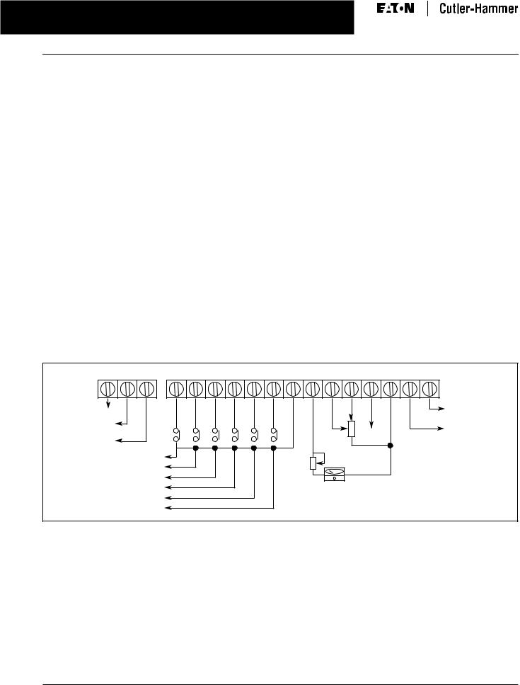
Wiring Diagrams
RO3 RO2 RO1 |
DI1 DI2 DI3 DI4 DI5 DI6 COM AO+ AI1 +10V AI2 COM DO1 DOC |
|
|
|
|
Factory Setting: |
|
NC Relay Output |
|
Inverter Running |
|
Factory Setting: |
|
Digital Output |
|
Inverter Fault |
4 Ð 20 mA |
||
|
|||
|
|
||
NO Relay Output |
|
|
|
|
Bias |
|
|
Forward/Stop |
Potentiometer |
|
|
Reverse/Stop |
|
|
|
Preset Speed 1 |
|
|
|
Preset Speed 2 |
Full Scale Voltmeter: |
|
|
Preset Speed 3 |
0 to 10V DC |
|
|
Factory Setting: |
|
||
|
|
||
Reset |
Output Frequency |
|
Figure 1. Control Terminal Wiring (Factory Settings)
For more information visit: www.EatonElectrical.com |
CA04000002E |
MVX9000 Adjustable Frequency Drives |
5 |
|
June 2006
Open Drives
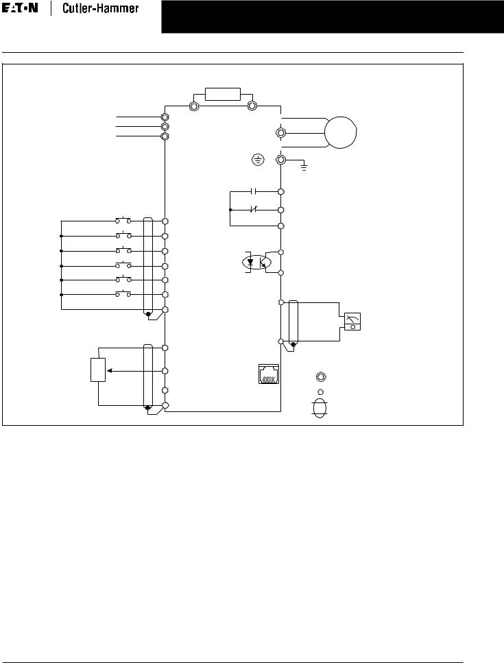
Braking Resistor
(Optional)
Main Circuit Power |
|
|
L1 |
L1 |
B1 |
|
||
L2 |
L2 |
|
L3 |
L3 |
|
Factory |
|
Default |
|
Start/Stop |
DI1 |
|
|
Reverse/Forward |
DI2 |
|
|
Preset Speed 1 |
DI3 |
|
|
Preset Speed 2 |
DI4 |
|
|
Preset Speed 3 |
DI5 |
|
|
Reset |
DI6 |
|
|
Common |
COM |
|
|
Reference Frequency Setting |
|
Factory Default Is Potentiometer |
|
Which Is on the Digital Keypad |
|
+10V 10 mA (Max)
3
Potentiometer |
VR 2 |
AI1 (0 Ð 10V DC) |
3K Ð 5KΩ |
|
|
|
1 |
AI2 (4 Ð 20 mA) |
|
|
COM |
B2 T1 
T2 |
AC |
|
Motor |
||
|
T3
Grounding Resistance
240V: Less Than 100Ω
480V: Less Than 10Ω
Factory Default: Inverter Fault
RO3 NO Relay Output
(120V AC/24V DC 5A)
RO1 |
NC Relay Output |
|
(120V AC/24V DC 5A) |
RO2 |
|
DO1
Digital Output (48V DC 50 mA)
Factory Default: Inverter Running
DOC
|
AO+ |
|
|
|
|
|
Analog Output |
|
|
|
DC 0 to 10V |
|
COM |
Factory Default: |
|
|
|
||
|
|
Output Frequency |
|
|
RJ-11 |
1,6: NC |
|
RS-485 |
|
|
|
|
2: GND |
|
|
Series |
|
Main Circuit (Power) Terminals |
|
|
3: SG- |
||
Interface |
6 to 1 |
4: SG+ |
|
|
|
||
|
5: +EV |
Control Circuit Terminals |
|
|
|
||
|
|
|
Shielded Leads |
Figure 2. Basic Wiring Diagram
Note: Do not plug a modem or telephone line to the RS-485 communication port, permanent damage may result. Terminals 2 and 5 are the power sources for the optional copy keypad and should not be used while using RS-485 communication.
■For single-phase application select correct model, and select any of the two input terminals for main circuit power.
CA04000002E |
For more information visit: www.EatonElectrical.com |

6MVX9000 Adjustable Frequency Drives
June 2006
Open Drives
Dimensions
Table 4. Approximate Dimensions and Shipping Weights for Basic Controller
Description |
|
Dimensions in Inches (mm) |
|
Shipping Weight |
||
|
|
|
|
|
Lbs. (kg) |
|
Horsepower |
Volts |
Width |
Height |
Depth |
||
|
||||||
|
|
|
|
|
|
|
|
|
|
|
|
|
|
1/4 |
100 Ð 120 |
3.9 (100) |
5.9 (151) |
5.7 (145) |
6.2 (2.8) |
|
1/2 |
|
3.9 (100) |
5.9 (151) |
5.7 (145) |
6.2 (2.8) |
|
1 |
|
3.9 (100) |
5.9 (151) |
5.7 (145) |
6.2 (2.8) |
|
|
|
|
|
|
|
|
1/2 |
200 Ð 240 |
3.9 (100) |
5.9 (151) |
5.7 (145) |
6.2 (2.8) |
|
1 |
|
3.9 (100) |
5.9 (151) |
5.7 (145) |
6.2 (2.8) |
|
2 |
|
3.9 (100) |
5.9 (151) |
5.7 (145) |
6.2 (2.8) |
|
3 |
|
4.9 (100) |
8.6 (220) |
7.6 (193) |
12.1 (5.5) |
|
5 |
|
4.9 (125) |
8.6 (220) |
7.6 (193) |
12.1 (5.5) |
|
7-1/2 |
|
4.9 (125) |
8.6 (220) |
7.6 (193) |
12.1 (5.5) |
|
|
|
|
|
|
|
|
1 |
380 Ð 480 |
3.9 (100) |
5.9 (151) |
5.7 (145) |
6.2 (2.8) |
|
2 |
|
3.9 (100) |
5.9 (151) |
5.7 (145) |
6.2 (2.8) |
|
3 |
|
3.9 (100) |
5.9 (151) |
5.7 (145) |
6.2 (2.8) |
|
5 |
|
4.9 (125) |
8.6 (220) |
7.6 (193) |
12.1 (5.5) |
|
7-1/2 |
|
4.9 (125) |
8.6 (220) |
7.6 (193) |
12.1 (5.5) |
|
10 |
|
4.9 (125) |
8.6 (220) |
7.6 (193) |
12.1 (5.5) |
|
|
|
|
|
|
|
|
1 |
500 Ð 600 |
3.9 (100) |
5.9 (151) |
5.7 (145) |
6.2 (2.8) |
|
2 |
|
3.9 (100) |
5.9 (151) |
5.7 (145) |
6.2 (2.8) |
|
3 |
|
3.9 (100) |
5.9 (151) |
5.7 (145) |
6.2 (2.8) |
|
5 |
|
4.9 (125) |
8.6 (220) |
7.6 (193) |
12.1 (5.5) |
|
7-1/2 |
|
4.9 (125) |
8.6 (220) |
7.6 (193) |
12.1 (5.5) |
|
10 |
|
4.9 (125) |
8.6 (220) |
7.6 (193) |
12.1 (5.5) |
|
|
|
|
|
|
|
|
|
5.62 (142.7) |
3.94 (100.0) |
5.22 (132.5) |
3.50 (89.0) |
.39 (10.0) |
|
.18 (4.5) |
|
Dia. Typ. |
5.94
(151.0)
6.34 (161.0) 5.51
(140.0)
3.35 (85.0)
.55 |
|
.08 |
1.77 |
(14.0) |
.39 |
(2.0) |
(45.0) |
.91 |
(10.0) |
|
|
|
|
|
|
(23.0) |
|
|
|
MOTOR Braking
T1 T2 T3 B1 B2
MVXF25A0-1 (115V, 1 ph 1/4 hp)
MVXF50A0-1 (115V, 1 ph 1/2 hp)
MVX001A0-1 (115V, 1 ph 1 hp)
MVXF50A0-2 (230V, 1 ph/3 ph, 1/2 hp)
MVX001A0-2 (230V, 1 ph/3 ph, 1 hp)
MVX002A0-2 (230V, 1 ph/3 ph, 2 hp)
MVX001A0-4 (460V, 3 ph, 1 hp)
MVX002A0-4 (460V, 3 ph, 2 hp)
MVX003A0-4 (460V, 3 ph, 3 hp)
MVX001A0-5 (575V, 3 ph 1 hp)
MVX002A0-5 (575V, 3 ph 2 hp)
MVX003A0-5 (575V, 3 ph 3 hp)
Figure 3. 1/4 to 3 hp Drive Approximate Dimensions in Inches (mm)
For more information visit: www.EatonElectrical.com |
CA04000002E |
 Loading...