


SPX9000 AF Drives
Application Manual
August 2005
New Information
MN04004001E |
For more information visit: www.EatonElectrical.com |

SPX9000 AF Drives
August 2005
Important Notice — Please Read
The product discussed in this literature is subject to terms and conditions outlined in Eaton Electrical Inc. selling policies. The sole source governing the rights and remedies of any purchaser of this equipment is the relevant Eaton Electrical Inc. selling policy.
NO WARRANTIES, EXPRESS OR IMPLIED, INCLUDING WARRANTIES OF FITNESS FOR A PARTICULAR PURPOSE OR MERCHANTABILITY, OR WARRANTIES ARISING FROM COURSE OF DEALING OR USAGE OF TRADE, ARE MADE REGARDING THE INFORMATION, RECOMMENDATIONS AND DESCRIPTIONS CONTAINED HEREIN. In no event will Eaton Electrical Inc. be responsible to the purchaser or user in contract, in tort (including negligence), strict liability or otherwise for any special, indirect, incidental or consequential damage or loss whatsoever, including but not limited to damage or loss of use of equipment, plant or power system, cost of capital, loss of power, additional expenses in the use of existing power facilities, or claims against the purchaser or user by its customers resulting from the use of the information, recommendations and descriptions contained herein.
The information contained in this manual is subject to change without notice.
Cover Photo: Cutler-Hammer® SPX9000 AF Drives.
MN04004001E |
For more information visit: www.EatonElectrical.com |
i |

SPX9000 AF Drives
|
|
|
August 2005 |
|
|
Contents |
|
|
|
|
|
Table of |
|
||
|
LIST OF FIGURES . . . . . . . . . . . . . . . . . . . . . . . . . . . . . . . . . . . . . . . . . . . . . . . . . . . . . . . . |
. iv |
|
|
LIST OF TABLES . . . . . . . . . . . . . . . . . . . . . . . . . . . . . . . . . . . . . . . . . . . . . . . . . . . . . . . . . . |
v |
|
|
CHAPTER 0 — SAFETY . . . . . . . . . . . . . . . . . . . . . . . . . . . . . . . . . . . . . . . . . . . . . . . . . . . . |
viii |
|
|
|
Definitions and Symbols . . . . . . . . . . . . . . . . . . . . . . . . . . . . . . . . . . . . . . . . . . . . . . . |
viii |
|
|
Hazardous High Voltage . . . . . . . . . . . . . . . . . . . . . . . . . . . . . . . . . . . . . . . . . . . . . . . |
viii |
|
|
Cautions and Notices . . . . . . . . . . . . . . . . . . . . . . . . . . . . . . . . . . . . . . . . . . . . . . . . . . |
ix |
|
CHAPTER 1 — BASIC APPLICATION (SVCHST01) . . . . . . . . . . . . . . . . . . . . . . . . . . . . . . |
1-1 |
|
|
|
Introduction . . . . . . . . . . . . . . . . . . . . . . . . . . . . . . . . . . . . . . . . . . . . . . . . . . . . . . . . . |
1-1 |
|
|
Control I/O. . . . . . . . . . . . . . . . . . . . . . . . . . . . . . . . . . . . . . . . . . . . . . . . . . . . . . . . . . . |
1-2 |
|
|
Basic Application — Parameter Lists . . . . . . . . . . . . . . . . . . . . . . . . . . . . . . . . . . . . . |
1-3 |
|
CHAPTER 2 — STANDARD APPLICATION (SVCHST02) . . . . . . . . . . . . . . . . . . . . . . . . . . |
2-1 |
|
|
|
Introduction . . . . . . . . . . . . . . . . . . . . . . . . . . . . . . . . . . . . . . . . . . . . . . . . . . . . . . . . . |
2-1 |
|
|
Control I/O. . . . . . . . . . . . . . . . . . . . . . . . . . . . . . . . . . . . . . . . . . . . . . . . . . . . . . . . . . . |
2-2 |
|
|
Standard Application — Parameter Lists . . . . . . . . . . . . . . . . . . . . . . . . . . . . . . . . . . |
2-3 |
|
CHAPTER 3 — LOCAL/REMOTE CONTROL APPLICATION (SVCHST03) . . . . . . . . . . . . |
3-1 |
|
|
|
Introduction . . . . . . . . . . . . . . . . . . . . . . . . . . . . . . . . . . . . . . . . . . . . . . . . . . . . . . . . . |
3-1 |
|
|
Control I/O. . . . . . . . . . . . . . . . . . . . . . . . . . . . . . . . . . . . . . . . . . . . . . . . . . . . . . . . . . . |
3-2 |
|
|
Local/Remote Control Application — Parameter Lists . . . . . . . . . . . . . . . . . . . . . . . |
3-3 |
|
CHAPTER 4 — MULTI-STEP SPEED CONTROL APPLICATION (SVCHST04) . . . . . . . . . |
4-1 |
|
|
|
Introduction . . . . . . . . . . . . . . . . . . . . . . . . . . . . . . . . . . . . . . . . . . . . . . . . . . . . . . . . . |
4-1 |
|
|
Control I/O. . . . . . . . . . . . . . . . . . . . . . . . . . . . . . . . . . . . . . . . . . . . . . . . . . . . . . . . . . . |
4-2 |
|
|
Multi-Step Speed Control Application — Parameter Lists . . . . . . . . . . . . . . . . . . . . |
4-3 |
|
CHAPTER 5 — PID CONTROL APPLICATION (SVCHST05) . . . . . . . . . . . . . . . . . . . . . . . . |
5-1 |
|
|
|
Introduction . . . . . . . . . . . . . . . . . . . . . . . . . . . . . . . . . . . . . . . . . . . . . . . . . . . . . . . . . |
5-1 |
|
|
Control I/O. . . . . . . . . . . . . . . . . . . . . . . . . . . . . . . . . . . . . . . . . . . . . . . . . . . . . . . . . . . |
5-2 |
|
|
PID Control Application — Parameter Lists . . . . . . . . . . . . . . . . . . . . . . . . . . . . . . . . |
5-3 |
|
CHAPTER 6 — MULTI-PURPOSE CONTROL APPLICATION (SVCHST06) . . . . . . . . . . . . |
6-1 |
|
|
|
Introduction . . . . . . . . . . . . . . . . . . . . . . . . . . . . . . . . . . . . . . . . . . . . . . . . . . . . . . . . . |
6-1 |
|
|
Control I/O. . . . . . . . . . . . . . . . . . . . . . . . . . . . . . . . . . . . . . . . . . . . . . . . . . . . . . . . . . . |
6-2 |
|
|
“Terminal To Function” (TTF) Programming Principle . . . . . . . . . . . . . . . . . . . . . . . |
6-3 |
|
|
Master/Follower Function (SPX Only) . . . . . . . . . . . . . . . . . . . . . . . . . . . . . . . . . . . . |
6-5 |
|
|
Multi-Purpose Control Application — Parameter Lists . . . . . . . . . . . . . . . . . . . . . . . |
6-7 |
|
|
Input Signals. . . . . . . . . . . . . . . . . . . . . . . . . . . . . . . . . . . . . . . . . . . . . . . . . . . . . . . . . |
6-10 |
|
|
Output Signals . . . . . . . . . . . . . . . . . . . . . . . . . . . . . . . . . . . . . . . . . . . . . . . . . . . . . . . |
6-15 |
|
CHAPTER 7 — PUMP AND FAN CONTROL APPLICATION (ASFIFF07) . . . . . . . . . . . . . . |
7-1 |
|
|
|
Introduction . . . . . . . . . . . . . . . . . . . . . . . . . . . . . . . . . . . . . . . . . . . . . . . . . . . . . . . . . |
7-1 |
|
|
Control I/O. . . . . . . . . . . . . . . . . . . . . . . . . . . . . . . . . . . . . . . . . . . . . . . . . . . . . . . . . . . |
7-2 |
|
|
Short Description of Function and Essential Parameters . . . . . . . . . . . . . . . . . . . . . |
7-5 |
|
|
Pump and Fan Control Application — Parameter Lists. . . . . . . . . . . . . . . . . . . . . . . |
7-10 |
|
|
Input Signals. . . . . . . . . . . . . . . . . . . . . . . . . . . . . . . . . . . . . . . . . . . . . . . . . . . . . . . . . |
7-13 |
|
|
Output Signals . . . . . . . . . . . . . . . . . . . . . . . . . . . . . . . . . . . . . . . . . . . . . . . . . . . . . . . |
7-17 |
ii |
For more information visit: www.EatonElectrical.com |
MN04004001E |

SPX9000 AF Drives
August 2005
Table of Contents, continued
CHAPTER 8 — DESCRIPTION OF PARAMETERS . . . . . . . . . . . . . . . . . . . . . . . . . . . . . . . . |
8-1 |
Introduction . . . . . . . . . . . . . . . . . . . . . . . . . . . . . . . . . . . . . . . . . . . . . . . . . . . . . . . . . . |
8-1 |
Keypad Control Parameters . . . . . . . . . . . . . . . . . . . . . . . . . . . . . . . . . . . . . . . . . . . . . |
8-84 |
APPENDIX A — ADDITIONAL INFORMATION . . . . . . . . . . . . . . . . . . . . . . . . . . . . . . . . . . |
A-1 |
External Brake Control with Additional Limits . . . . . . . . . . . . . . . . . . . . . . . . . . . . . . |
A-1 |
Closed Loop Parameters. . . . . . . . . . . . . . . . . . . . . . . . . . . . . . . . . . . . . . . . . . . . . . . . |
A-3 |
Advanced Open Loop Parameters . . . . . . . . . . . . . . . . . . . . . . . . . . . . . . . . . . . . . . . . |
A-3 |
Parameters of Motor Thermal Protection . . . . . . . . . . . . . . . . . . . . . . . . . . . . . . . . . . |
A-4 |
Parameters of Stall Protection . . . . . . . . . . . . . . . . . . . . . . . . . . . . . . . . . . . . . . . . . . . |
A-4 |
Parameters of Underload Protection . . . . . . . . . . . . . . . . . . . . . . . . . . . . . . . . . . . . . . |
A-5 |
Fieldbus Control Parameters . . . . . . . . . . . . . . . . . . . . . . . . . . . . . . . . . . . . . . . . . . . . |
A-5 |
MN04004001E |
For more information visit: www.EatonElectrical.com |
iii |

SPX9000 AF Drives
|
August 2005 |
List of Figures |
|
Figure 6-1: Defining Input/Output — Function . . . . . . . . . . . . . . . . . . . . . . . . . . . . . . . . |
. 6-3 |
Figure 6-2: Defining Input/Output — Values . . . . . . . . . . . . . . . . . . . . . . . . . . . . . . . . . . |
. 6-3 |
Figure 6-3: Screenshot of 9000X Drive Programming Tool; |
|
Entering the Address Code . . . . . . . . . . . . . . . . . . . . . . . . . . . . . . . . . . . . . . . . . . . . . . |
6-4 |
Figure 6-4: System Bus Physical Connections with the OPT-D2 Board . . . . . . . . . . . . . . |
6-5 |
Figure 6-5: System Bus Physical Connections with the OPT-D1 Board . . . . . . . . . . . . . . |
6-6 |
Figure 7-1: 2-Pump Autochange System Principal Control Diagram . . . . . . . . . . . . . . . |
7-3 |
Figure 7-2: 3-Pump Autochange System Principal Control Diagram . . . . . . . . . . . . . . . |
7-4 |
Figure 7-3: Example of the Function of the PFC Application with |
|
Three Aux. Drives . . . . . . . . . . . . . . . . . . . . . . . . . . . . . . . . . . . . . . . . . . . . . . . . . . . . . |
7-8 |
Figure 7-4: Example of 2-Pump Autochange, Main Diagram . . . . . . . . . . . . . . . . . . . . . . |
7-9 |
Figure 7-5: Example of 3-Pump Autochange, Main Diagram . . . . . . . . . . . . . . . . . . . . . . |
7-9 |
Figure 8-1: Linear and Squared Change of Motor Voltage . . . . . . . . . . . . . . . . . . . . . . . . |
8-2 |
Figure 8-2: Programmable V/Hz Curve . . . . . . . . . . . . . . . . . . . . . . . . . . . . . . . . . . . . . . . . |
8-3 |
Figure 8-3: PID Controller Function as I-Controller . . . . . . . . . . . . . . . . . . . . . . . . . . . . . . |
8-6 |
Figure 8-4: PID Output Curve with the Values of Example 2 . . . . . . . . . . . . . . . . . . . . . . |
8-6 |
Figure 8-5: PID Output Curve with the Values of Example 3 . . . . . . . . . . . . . . . . . . . . . . |
8-7 |
Figure 8-6: Start Forward/Start Reverse . . . . . . . . . . . . . . . . . . . . . . . . . . . . . . . . . . . . . . . |
8-11 |
Figure 8-7: Start, Stop and Reverse . . . . . . . . . . . . . . . . . . . . . . . . . . . . . . . . . . . . . . . . . . |
8-11 |
Figure 8-8: Start Pulse/Stop Pulse . . . . . . . . . . . . . . . . . . . . . . . . . . . . . . . . . . . . . . . . . . . |
8-12 |
Figure 8-9: DIN3 as DC-Brake Command Input . . . . . . . . . . . . . . . . . . . . . . . . . . . . . . . . . |
8-15 |
Figure 8-10: With and Without Reference Scaling . . . . . . . . . . . . . . . . . . . . . . . . . . . . . . |
8-15 |
Figure 8-11: Reference Inversion . . . . . . . . . . . . . . . . . . . . . . . . . . . . . . . . . . . . . . . . . . . . |
8-16 |
Figure 8-12: Reference Filtering . . . . . . . . . . . . . . . . . . . . . . . . . . . . . . . . . . . . . . . . . . . . . |
8-16 |
Figure 8-13: Analog Output Filtering . . . . . . . . . . . . . . . . . . . . . . . . . . . . . . . . . . . . . . . . . |
8-17 |
Figure 8-14: Analog Output Invert . . . . . . . . . . . . . . . . . . . . . . . . . . . . . . . . . . . . . . . . . . . |
8-17 |
Figure 8-15: Analog Output Scaling . . . . . . . . . . . . . . . . . . . . . . . . . . . . . . . . . . . . . . . . . . |
8-18 |
Figure 8-16: Output Frequency Supervision . . . . . . . . . . . . . . . . . . . . . . . . . . . . . . . . . . . |
8-20 |
Figure 8-17: DC Braking Command (Selection 12) Selected for DIN2 . . . . . . . . . . . . . . . |
8-22 |
Figure 8-18: AI1 No Signal Inversion . . . . . . . . . . . . . . . . . . . . . . . . . . . . . . . . . . . . . . . . . |
8-23 |
Figure 8-19: AI1 Signal Inversion . . . . . . . . . . . . . . . . . . . . . . . . . . . . . . . . . . . . . . . . . . . . |
8-23 |
Figure 8-20: AI1 Signal Filtering . . . . . . . . . . . . . . . . . . . . . . . . . . . . . . . . . . . . . . . . . . . . . |
8-24 |
Figure 8-21: Analog Input AI2 Scaling . . . . . . . . . . . . . . . . . . . . . . . . . . . . . . . . . . . . . . . . |
8-24 |
Figure 8-22: Examples of Actual Value Signal Scaling . . . . . . . . . . . . . . . . . . . . . . . . . . . |
8-27 |
Figure 8-23: Control Place B with and without Reference Scaling . . . . . . . . . . . . . . . . . |
8-28 |
Figure 8-24: External Brake Control . . . . . . . . . . . . . . . . . . . . . . . . . . . . . . . . . . . . . . . . . . |
8-30 |
Figure 8-25: An Example of On/Off-Control . . . . . . . . . . . . . . . . . . . . . . . . . . . . . . . . . . . . |
8-31 |
Figure 8-26: Scaling of Max. Motor Current . . . . . . . . . . . . . . . . . . . . . . . . . . . . . . . . . . . |
8-32 |
Figure 8-27: Reduction of DC Braking Current . . . . . . . . . . . . . . . . . . . . . . . . . . . . . . . . . |
8-32 |
Figure 8-28: Reduction of Acceleration and |
|
Deceleration Times . . . . . . . . . . . . . . . . . . . . . . . . . . . . . . . . . . . . . . . . . . . . . . . . . . . . |
8-33 |
Figure 8-29: Reduction of Torque Supervision Limit . . . . . . . . . . . . . . . . . . . . . . . . . . . . |
8-33 |
Figure 8-30: Place B Start Forward/Start Reverse . . . . . . . . . . . . . . . . . . . . . . . . . . . . . . . |
8-34 |
Figure 8-31: Place B Start, Stop, Reverse . . . . . . . . . . . . . . . . . . . . . . . . . . . . . . . . . . . . . . |
8-34 |
Figure 8-32: Place B Start Pulse/Stop Pulse . . . . . . . . . . . . . . . . . . . . . . . . . . . . . . . . . . . . |
8-35 |
Figure 8-33: PID Sum Point Reference . . . . . . . . . . . . . . . . . . . . . . . . . . . . . . . . . . . . . . . . |
8-37 |
Figure 8-34: An Example of Joystick Hysteresis . . . . . . . . . . . . . . . . . . . . . . . . . . . . . . . . |
8-38 |
Figure 8-35: Example of Sleep Limit Function . . . . . . . . . . . . . . . . . . . . . . . . . . . . . . . . . . |
8-39 |
Figure 8-36: Joystick Hysteresis with Minimum Frequency at 35 Hz . . . . . . . . . . . . . . . |
8-40 |
Figure 8-37: Scaling of DC-Braking Current . . . . . . . . . . . . . . . . . . . . . . . . . . . . . . . . . . . . |
8-41 |
iv |
For more information visit: www.EatonElectrical.com |
MN04004001E |

SPX9000 AF Drives
August 2005
List of Figures, continued
Figure 8-38: Reducing Acceleration and Deceleration Times . . . . . . . . . . . . . . . . . . . . . . |
8-42 |
Figure 8-39: Reducing Torque Supervision Limit . . . . . . . . . . . . . . . . . . . . . . . . . . . . . . . . |
8-42 |
Figure 8-40: Digital Outputs 1 and 2, Onand Off-Delays . . . . . . . . . . . . . . . . . . . . . . . . . |
8-49 |
Figure 8-41: An Example of Adjust Input . . . . . . . . . . . . . . . . . . . . . . . . . . . . . . . . . . . . . . |
8-50 |
Figure 8-42: Acceleration/Deceleration (S-shaped) . . . . . . . . . . . . . . . . . . . . . . . . . . . . . . |
8-51 |
Figure 8-43: DC-Braking Time when Stop Mode = Coasting . . . . . . . . . . . . . . . . . . . . . . . |
8-53 |
Figure 8-44: DC-Braking Time when Stop Mode = Ramp . . . . . . . . . . . . . . . . . . . . . . . . . |
8-54 |
Figure 8-45: Example of Prohibit Frequency Area Setting . . . . . . . . . . . . . . . . . . . . . . . . |
8-55 |
Figure 8-46: Ramp Speed Scaling between |
|
Prohibit Frequencies . . . . . . . . . . . . . . . . . . . . . . . . . . . . . . . . . . . . . . . . . . . . . . . . . . . . |
8-56 |
Figure 8-47: Motor Thermal Current IT Curve . . . . . . . . . . . . . . . . . . . . . . . . . . . . . . . . . . |
8-63 |
Figure 8-48: Motor Temperature Calculation . . . . . . . . . . . . . . . . . . . . . . . . . . . . . . . . . . . |
8-64 |
Figure 8-49: Stall Characteristics Settings . . . . . . . . . . . . . . . . . . . . . . . . . . . . . . . . . . . . . |
8-65 |
Figure 8-50: Stall Time Count . . . . . . . . . . . . . . . . . . . . . . . . . . . . . . . . . . . . . . . . . . . . . . . . |
8-65 |
Figure 8-51: Setting of Minimum Load . . . . . . . . . . . . . . . . . . . . . . . . . . . . . . . . . . . . . . . . |
8-66 |
Figure 8-52: Underload Time Counter Function . . . . . . . . . . . . . . . . . . . . . . . . . . . . . . . . . |
8-67 |
Figure 8-53: Example of Automatic Restarts with Two Restarts . . . . . . . . . . . . . . . . . . . . |
8-68 |
Figure 8-54: Example of Parameter Setting . . . . . . . . . . . . . . . . . . . . . . . . . . . . . . . . . . . . |
8-74 |
Figure 8-55: Reference Steps after Starting Auxiliary Drives . . . . . . . . . . . . . . . . . . . . . . |
8-75 |
Figure 8-56: Frequency Converter Sleep Function . . . . . . . . . . . . . . . . . . . . . . . . . . . . . . . |
8-76 |
Figure 8-57: Example of Adjustable Frequency Drive and |
|
Two Auxiliary Drives with Bypassed PID Controller . . . . . . . . . . . . . . . . . . . . . . . . . . |
8-78 |
Figure 8-58: Input and Output Pressure Measuring . . . . . . . . . . . . . . . . . . . . . . . . . . . . . . |
8-79 |
Figure 8-59: Output Pressure Behavior Depending on |
|
Input Pressure and Parameter Settings . . . . . . . . . . . . . . . . . . . . . . . . . . . . . . . . . . . . |
8-79 |
Figure 8-60: Frequency Drop and Increase Delays . . . . . . . . . . . . . . . . . . . . . . . . . . . . . . . |
8-80 |
Figure 8-61: Autochange Applied to Auxiliary Drives Only . . . . . . . . . . . . . . . . . . . . . . . . |
8-81 |
Figure 8-62: Autochange with All Drives . . . . . . . . . . . . . . . . . . . . . . . . . . . . . . . . . . . . . . . |
8-81 |
Figure 8-63: Autochange Interval and Limits . . . . . . . . . . . . . . . . . . . . . . . . . . . . . . . . . . . |
8-82 |
Figure 8-64: Actual Value Special Display . . . . . . . . . . . . . . . . . . . . . . . . . . . . . . . . . . . . . . |
8-83 |
Figure A-1: Brake Control with Additional Limits . . . . . . . . . . . . . . . . . . . . . . . . . . . . . . . . |
A-1 |
Figure A-2: Brake Control Logic . . . . . . . . . . . . . . . . . . . . . . . . . . . . . . . . . . . . . . . . . . . . . . |
A-2 |
List of Tables
Table 1-1: Basic Application Default I/O Configuration . . . . . . . . . . . . . . . . . . . . . . . . . . . |
1-2 |
Table 1-2: Monitoring Values. . . . . . . . . . . . . . . . . . . . . . . . . . . . . . . . . . . . . . . . . . . . . . . . . |
1-3 |
Table 1-3: Basic Parameters — G1 . . . . . . . . . . . . . . . . . . . . . . . . . . . . . . . . . . . . . . . . . . . . |
1-4 |
Table 1-4: Keypad Control Parameters — M2 . . . . . . . . . . . . . . . . . . . . . . . . . . . . . . . . . . . |
1-5 |
Table 2-1: Standard Application Default I/O Configuration . . . . . . . . . . . . . . . . . . . . . . . . |
2-2 |
Table 2-2: Monitoring Values. . . . . . . . . . . . . . . . . . . . . . . . . . . . . . . . . . . . . . . . . . . . . . . . . |
2-3 |
Table 2-3: Basic Parameters — G1.1 . . . . . . . . . . . . . . . . . . . . . . . . . . . . . . . . . . . . . . . . . . . |
2-4 |
Table 2-4: Input Signals — G1.2 . . . . . . . . . . . . . . . . . . . . . . . . . . . . . . . . . . . . . . . . . . . . . . |
2-5 |
Table 2-5: Output Signals — G1.3 . . . . . . . . . . . . . . . . . . . . . . . . . . . . . . . . . . . . . . . . . . . . . |
2-5 |
Table 2-6: Drive Control Parameters — G1.4 . . . . . . . . . . . . . . . . . . . . . . . . . . . . . . . . . . . . |
2-7 |
Table 2-7: Prohibit Frequency Parameters — G1.5 . . . . . . . . . . . . . . . . . . . . . . . . . . . . . . . |
2-7 |
Table 2-8: Motor Control Parameters — G1.6 . . . . . . . . . . . . . . . . . . . . . . . . . . . . . . . . . . . |
2-8 |
Table 2-9: Protections — G1.7 . . . . . . . . . . . . . . . . . . . . . . . . . . . . . . . . . . . . . . . . . . . . . . . . |
2-9 |
Table 2-10: Autorestart Parameters — G1.8. . . . . . . . . . . . . . . . . . . . . . . . . . . . . . . . . . . . . |
2-10 |
Table 2-11: Keypad Control Parameters — M2 . . . . . . . . . . . . . . . . . . . . . . . . . . . . . . . . . . |
2-11 |
MN04004001E |
For more information visit: www.EatonElectrical.com |
v |

SPX9000 AF Drives
|
August 2005 |
List of Tables, continued |
|
Table 3-1: Local/Remote Application Default I/O Configuration . . . . . . . . . . . . . . . . . . . |
. 3-2 |
Table 3-2: Monitoring Values . . . . . . . . . . . . . . . . . . . . . . . . . . . . . . . . . . . . . . . . . . . . . . . |
. 3-3 |
Table 3-3: Basic Parameters — G1.1 . . . . . . . . . . . . . . . . . . . . . . . . . . . . . . . . . . . . . . . . . . |
3-4 |
Table 3-4: Input Signals — G1.2. . . . . . . . . . . . . . . . . . . . . . . . . . . . . . . . . . . . . . . . . . . . . . |
3-5 |
Table 3-5: Output Signals — G1.3 . . . . . . . . . . . . . . . . . . . . . . . . . . . . . . . . . . . . . . . . . . . . |
3-7 |
Table 3-6: Drive Control Parameters — G1.4 . . . . . . . . . . . . . . . . . . . . . . . . . . . . . . . . . . . |
3-9 |
Table 3-7: Prohibit Frequency Parameters — G1.5. . . . . . . . . . . . . . . . . . . . . . . . . . . . . . . |
3-10 |
Table 3-8: Motor Control Parameters — G1.6. . . . . . . . . . . . . . . . . . . . . . . . . . . . . . . . . . . |
3-10 |
Table 3-9: Protections — G1.7 . . . . . . . . . . . . . . . . . . . . . . . . . . . . . . . . . . . . . . . . . . . . . . . |
3-12 |
Table 3-10: Autorestart Parameters — G1.8 . . . . . . . . . . . . . . . . . . . . . . . . . . . . . . . . . . . . |
3-13 |
Table 3-11: Keypad Control Parameters — M2. . . . . . . . . . . . . . . . . . . . . . . . . . . . . . . . . . |
3-14 |
Table 4-1: Multi-Step Speed Control Application Default I/O Configuration . . . . . . . . . . |
4-2 |
Table 4-2: Monitoring Values . . . . . . . . . . . . . . . . . . . . . . . . . . . . . . . . . . . . . . . . . . . . . . . . |
4-3 |
Table 4-3: Basic Parameters — G1.1 . . . . . . . . . . . . . . . . . . . . . . . . . . . . . . . . . . . . . . . . . . |
4-4 |
Table 4-4: Input Signals — G1.2. . . . . . . . . . . . . . . . . . . . . . . . . . . . . . . . . . . . . . . . . . . . . . |
4-5 |
Table 4-5: Output Signals — G1.3 . . . . . . . . . . . . . . . . . . . . . . . . . . . . . . . . . . . . . . . . . . . . |
4-7 |
Table 4-6: Drive Control Parameters — G1.4 . . . . . . . . . . . . . . . . . . . . . . . . . . . . . . . . . . . |
4-9 |
Table 4-7: Prohibit Frequency Parameters — G1.5. . . . . . . . . . . . . . . . . . . . . . . . . . . . . . . |
4-9 |
Table 4-8: Motor Control Parameters — G1.6 . . . . . . . . . . . . . . . . . . . . . . . . . . . . . . . . . . |
4-10 |
Table 4-9: Protections — G1.7 . . . . . . . . . . . . . . . . . . . . . . . . . . . . . . . . . . . . . . . . . . . . . . . |
4-12 |
Table 4-10: Autorestart Parameters — G1.8 . . . . . . . . . . . . . . . . . . . . . . . . . . . . . . . . . . . . |
4-13 |
Table 4-11: Keypad Control Parameters — M2. . . . . . . . . . . . . . . . . . . . . . . . . . . . . . . . . . |
4-13 |
Table 5-1: PID Application Default I/O Configuration (with 2-wire transmitter). . . . . . . . |
5-2 |
Table 5-2: Monitoring Values . . . . . . . . . . . . . . . . . . . . . . . . . . . . . . . . . . . . . . . . . . . . . . . . |
5-3 |
Table 5-3: Basic Parameters — G1.1 . . . . . . . . . . . . . . . . . . . . . . . . . . . . . . . . . . . . . . . . . . |
5-4 |
Table 5-4: Input Signals — G1.2. . . . . . . . . . . . . . . . . . . . . . . . . . . . . . . . . . . . . . . . . . . . . . |
5-6 |
Table 5-5: Output Signals — G1.3 . . . . . . . . . . . . . . . . . . . . . . . . . . . . . . . . . . . . . . . . . . . . |
5-9 |
Table 5-6: Drive Control Parameters — G1.4 . . . . . . . . . . . . . . . . . . . . . . . . . . . . . . . . . . . |
5-11 |
Table 5-7: Prohibit Frequency Parameters — G1.5. . . . . . . . . . . . . . . . . . . . . . . . . . . . . . . |
5-11 |
Table 5-8: Motor Control Parameters — G1.6. . . . . . . . . . . . . . . . . . . . . . . . . . . . . . . . . . . |
5-12 |
Table 5-9: Protections — G1.7 . . . . . . . . . . . . . . . . . . . . . . . . . . . . . . . . . . . . . . . . . . . . . . . |
5-14 |
Table 5-10: Autorestart Parameters — G1.8 . . . . . . . . . . . . . . . . . . . . . . . . . . . . . . . . . . . . |
5-15 |
Table 5-11: Keypad Control Parameters — M2. . . . . . . . . . . . . . . . . . . . . . . . . . . . . . . . . . |
5-16 |
Table 6-1: Multi-Purpose Control Application Default I/O Configuration and |
|
Connection Example . . . . . . . . . . . . . . . . . . . . . . . . . . . . . . . . . . . . . . . . . . . . . . . . . . . |
6-2 |
Table 6-2: Monitoring Values, SPX Drives . . . . . . . . . . . . . . . . . . . . . . . . . . . . . . . . . . . . . |
6-7 |
Table 6-3: Basic Parameters — G1.1 . . . . . . . . . . . . . . . . . . . . . . . . . . . . . . . . . . . . . . . . . . |
6-8 |
Table 6-4: Input Signals: Basic Settings — G1.2.1 . . . . . . . . . . . . . . . . . . . . . . . . . . . . . . . |
6-10 |
Table 6-5: Analog Input 1 Parameters — G1.2.2. . . . . . . . . . . . . . . . . . . . . . . . . . . . . . . . . |
6-10 |
Table 6-6: Analog Input 2 Parameters — G1.2.3. . . . . . . . . . . . . . . . . . . . . . . . . . . . . . . . . |
6-11 |
Table 6-7: Analog Input 3 Parameters — G1.2.4. . . . . . . . . . . . . . . . . . . . . . . . . . . . . . . . . |
6-12 |
Table 6-8: Analog Input 4 Parameters — G1.2.5. . . . . . . . . . . . . . . . . . . . . . . . . . . . . . . . . |
6-12 |
Table 6-9: Free Analog Input Signal Selection — G1.2.6 . . . . . . . . . . . . . . . . . . . . . . . . . . |
6-13 |
Table 6-10: Digital Input Signals — G1.2.7 . . . . . . . . . . . . . . . . . . . . . . . . . . . . . . . . . . . . . |
6-13 |
Table 6-11: Delayed Digital Output 1 Parameters — G1.3.1 . . . . . . . . . . . . . . . . . . . . . . . |
6-15 |
Table 6-12: Delayed Digital Output 2 Parameters — G1.3.2 . . . . . . . . . . . . . . . . . . . . . . . |
6-15 |
Table 6-13: Digital Output Signals — G1.3.3. . . . . . . . . . . . . . . . . . . . . . . . . . . . . . . . . . . . |
6-16 |
Table 6-14: Limit Settings — G1.3.4. . . . . . . . . . . . . . . . . . . . . . . . . . . . . . . . . . . . . . . . . . . |
6-17 |
Table 6-15: Analog Output 1 Parameters — G1.3.5 . . . . . . . . . . . . . . . . . . . . . . . . . . . . . . |
6-18 |
Table 6-16: Analog Output 2 Parameters — G1.3.6 . . . . . . . . . . . . . . . . . . . . . . . . . . . . . . |
6-19 |
Table 6-17: Analog Output 3 Parameters — G1.3.7 . . . . . . . . . . . . . . . . . . . . . . . . . . . . . . |
6-19 |
Table 6-18: Drive Control Parameters — G1.4 . . . . . . . . . . . . . . . . . . . . . . . . . . . . . . . . . . |
6-20 |
Table 6-19: Prohibit Frequency Parameters — G1.5. . . . . . . . . . . . . . . . . . . . . . . . . . . . . . |
6-21 |
Table 6-20: Motor Control Parameters — G1.6. . . . . . . . . . . . . . . . . . . . . . . . . . . . . . . . . . |
6-21 |
vi |
For more information visit: www.EatonElectrical.com |
MN04004001E |

SPX9000 AF Drives
August 2005
List of Tables, continued
Table 6-21: Protections — G1.7 . . . . . . . . . . . . . . . . . . . . . . . . . . . . . . . . . . . . . . . . . . . . . . . |
6-23 |
Table 6-22: Autorestart Parameters — G1.8. . . . . . . . . . . . . . . . . . . . . . . . . . . . . . . . . . . . . |
6-25 |
Table 6-23: Fieldbus Parameters — G1.9 . . . . . . . . . . . . . . . . . . . . . . . . . . . . . . . . . . . . . . . |
6-25 |
Table 6-24: Torque Control Parameters — G1.10. . . . . . . . . . . . . . . . . . . . . . . . . . . . . . . . . |
6-26 |
Table 6-25: Keypad Control Parameters — M2 . . . . . . . . . . . . . . . . . . . . . . . . . . . . . . . . . . |
6-27 |
Table 7-1: Pump and Fan Control Application Default I/O Configuration and |
|
Connection Example (with 2-wire transmitter) . . . . . . . . . . . . . . . . . . . . . . . . . . . . . . . |
7-2 |
Table 7-2: Monitoring Values. . . . . . . . . . . . . . . . . . . . . . . . . . . . . . . . . . . . . . . . . . . . . . . . . |
7-10 |
Table 7-3: Basic Parameters — G1.1 . . . . . . . . . . . . . . . . . . . . . . . . . . . . . . . . . . . . . . . . . . . |
7-11 |
Table 7-4: Input Signals, Basic Settings — G1.2.1 . . . . . . . . . . . . . . . . . . . . . . . . . . . . . . . . |
7-13 |
Table 7-5: Input Signals, Analog Input 1 — G1.2.2 . . . . . . . . . . . . . . . . . . . . . . . . . . . . . . . |
7-14 |
Table 7-6: Input Signals, Analog Input 2 — G1.2.3 . . . . . . . . . . . . . . . . . . . . . . . . . . . . . . . |
7-14 |
Table 7-7: Input Signals, Analog Input 3 — G1.2.4 . . . . . . . . . . . . . . . . . . . . . . . . . . . . . . . |
7-15 |
Table 7-8: Input Signals, Analog Input 4 — G1.2.5 . . . . . . . . . . . . . . . . . . . . . . . . . . . . . . . |
7-15 |
Table 7-9: Input Signals, Digital Inputs — G1.2.6 . . . . . . . . . . . . . . . . . . . . . . . . . . . . . . . . |
7-15 |
Table 7-10: Output Signals, Digital Outputs — G1.3.1 . . . . . . . . . . . . . . . . . . . . . . . . . . . . |
7-17 |
Table 7-11: Output Signals, Limit Settings — G1.3.2 . . . . . . . . . . . . . . . . . . . . . . . . . . . . . |
7-18 |
Table 7-12: Output Signals, Analog Output 1 — G1.3.3 . . . . . . . . . . . . . . . . . . . . . . . . . . . |
7-19 |
Table 7-13: Output Signals, Analog Output 2 — G1.3.4 . . . . . . . . . . . . . . . . . . . . . . . . . . . |
7-20 |
Table 7-14: Output Signals, Analog Output 3 — G1.3.5 . . . . . . . . . . . . . . . . . . . . . . . . . . . |
7-20 |
Table 7-15: Drive Control Parameters — G1.4 . . . . . . . . . . . . . . . . . . . . . . . . . . . . . . . . . . . |
7-21 |
Table 7-16: Skip Frequencies— G1.5 . . . . . . . . . . . . . . . . . . . . . . . . . . . . . . . . . . . . . . . . . . |
7-22 |
Table 7-17: Motor Control Parameters — G1.6 . . . . . . . . . . . . . . . . . . . . . . . . . . . . . . . . . . |
7-22 |
Table 7-18: Protections — G1.7 . . . . . . . . . . . . . . . . . . . . . . . . . . . . . . . . . . . . . . . . . . . . . . . |
7-23 |
Table 7-19: Autorestart Parameters — G1.8. . . . . . . . . . . . . . . . . . . . . . . . . . . . . . . . . . . . . |
7-24 |
Table 7-20: Pump and Fan Control Parameters — G1.9 . . . . . . . . . . . . . . . . . . . . . . . . . . . |
7-25 |
Table 7-21: Keypad Control Parameters — M2 . . . . . . . . . . . . . . . . . . . . . . . . . . . . . . . . . . |
7-26 |
Table 8-1: Preset Speed . . . . . . . . . . . . . . . . . . . . . . . . . . . . . . . . . . . . . . . . . . . . . . . . . . . . . |
8-1 |
Table 8-2: Preset Speeds 3 to 7 . . . . . . . . . . . . . . . . . . . . . . . . . . . . . . . . . . . . . . . . . . . . . . . |
8-5 |
Table 8-3: Multi-Step Speed Selections with Digital Inputs DIN3, DIN4, |
|
DIN5 and DIN6 . . . . . . . . . . . . . . . . . . . . . . . . . . . . . . . . . . . . . . . . . . . . . . . . . . . . . . . . . |
8-7 |
Table 8-4: Selections for ID143 . . . . . . . . . . . . . . . . . . . . . . . . . . . . . . . . . . . . . . . . . . . . . . . |
8-8 |
Table 8-5: Selections for ID171 and ID172 . . . . . . . . . . . . . . . . . . . . . . . . . . . . . . . . . . . . . . |
8-9 |
Table 8-6: Selections for ID173 and ID174 . . . . . . . . . . . . . . . . . . . . . . . . . . . . . . . . . . . . . . |
8-10 |
Table 8-7: Analog Output Scaling . . . . . . . . . . . . . . . . . . . . . . . . . . . . . . . . . . . . . . . . . . . . . |
8-18 |
Table 8-8: Output Signals Via DO1 and Output Relays RO1 and RO2 . . . . . . . . . . . . . . . . |
8-19 |
Table 8-9: Selections for ID320 . . . . . . . . . . . . . . . . . . . . . . . . . . . . . . . . . . . . . . . . . . . . . . . |
8-22 |
Table 8-10: Selections for Parameter ID325 . . . . . . . . . . . . . . . . . . . . . . . . . . . . . . . . . . . . . |
8-24 |
Table 8-11: Selections for ID332 . . . . . . . . . . . . . . . . . . . . . . . . . . . . . . . . . . . . . . . . . . . . . . |
8-25 |
Table 8-12: Size-Dependent Switching Frequencies . . . . . . . . . . . . . . . . . . . . . . . . . . . . . |
8-57 |
Table 8-13: Typical Monitored Items . . . . . . . . . . . . . . . . . . . . . . . . . . . . . . . . . . . . . . . . . . |
8-72 |
Table 8-14: Selectable Wake-Up Functions . . . . . . . . . . . . . . . . . . . . . . . . . . . . . . . . . . . . . |
8-77 |
MN04004001E |
For more information visit: www.EatonElectrical.com |
vii |
SPX9000 AF Drives
August 2005
Safety
Definitions and Symbols
WARNING
This symbol indicates high voltage. It calls your attention to items or operations that could be dangerous to you and other persons operating this equipment. Read the message and follow the instructions carefully.
This symbol is the “Safety Alert Symbol.” It occurs with either of two signal words: CAUTION or WARNING, as described below.
WARNING
Indicates a potentially hazardous situation which, if not avoided, can result in serious injury or death.
CAUTION
Indicates a potentially hazardous situation which, if not avoided, can result in minor to moderate injury, or serious damage to the product. The situation described in the CAUTION may, if not avoided, lead to serious results. Important safety measures are described in CAUTION (as well as WARNING).
Hazardous High Voltage
WARNING
Motor control equipment and electronic controllers are connected to hazardous line voltages. When servicing drives and electronic controllers, there may be exposed components with housings or protrusions at or above line potential. Extreme care should be taken to protect against shock.
Stand on an insulating pad and make it a habit to use only one hand when checking components. Always work with another person in case an emergency occurs. Disconnect power before checking controllers or performing maintenance. Be sure equipment is properly grounded. Wear safety glasses whenever working on electronic controllers or rotating machinery.
viii |
For more information visit: www.EatonElectrical.com |
MN04004001E |
SPX9000 AF Drives
August 2005
Cautions and Notices
Read this manual thoroughly and make sure you understand the procedures before you attempt to install, set up, or operate this Cutler-Hammer® SPX9000 AF Drives from Eaton’s electrical business.
Cautions
CAUTION
Be ABSOLUTELY sure not to connect two functions to one and same output in order to avoid function overruns and to ensure flawless operation.
CAUTION
The calculated model does not protect the motor if the airflow to the motor is reduced by blocked air intake grill.
Notices
Notice
The inputs, unlike the outputs, cannot be changed in RUN state.
MN04004001E |
For more information visit: www.EatonElectrical.com |
ix |

SPX9000 AF Drives
August 2005
x |
For more information visit: www.EatonElectrical.com |
MN04004001E |

SPX9000 AF Drives
August 2005
Chapter 1 — Basic Application (SVCHST01)
Introduction
The Basic Application is easy and flexible to use due to its versatile fieldbus features. It is the default setting on delivery from the factory. Otherwise select the Basic Application in menu
M5. See Chapter 5 of the SVX9000 AF Drives User Manual.
Digital input DIN3 is programmable.
The parameters of the Basic Application are explained in Chapter 8 of this manual. The explanations are arranged according to the individual ID number of the parameter.
Motor Protection Functions in the Basic Application
The Basic Application provides almost all the same protection functions as the other applications:
●External fault protection
●Input phase supervision
●Undervoltage protection
●Output phase supervision
●Earth fault protection
●Motor thermal protection
●Thermistor fault protection
●Fieldbus fault protection
●Slot fault protection
Unlike the other applications, the Basic Application does not provide any parameters for choosing the response function or limit values for the faults. The motor thermal protection is explained in more detail on Page A-4 in Appendix A.
MN04004001E |
For more information visit: www.EatonElectrical.com |
1-1 |
SPX9000 AF Drives
August 2005
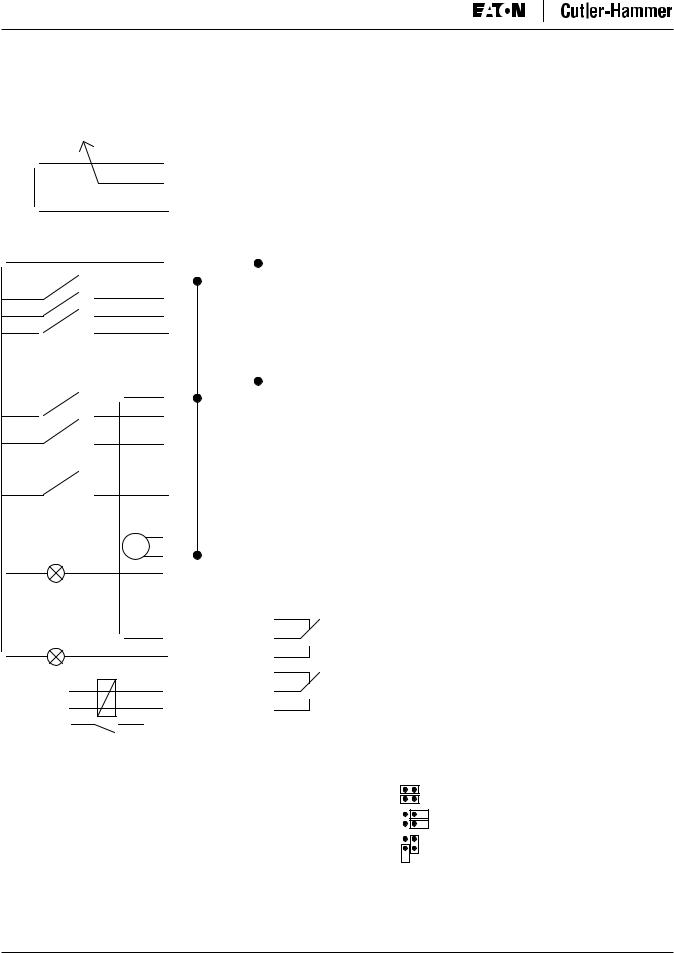
Control I/O
Reference potentiometer |
Table 1-1: Basic Application Default I/O Configuration |
|
|
|
||||||||||||||||||||||||||||||||
1 – 10 kΩ |
|
|
|
|
|
|
|
|
|
|
|
|
|
|
|
|||||||||||||||||||||
Terminal |
Signal |
|
Description |
|
||||||||||||||||||||||||||||||||
|
|
|
|
|
|
|
|
|
|
|
|
|
|
|
|
|
|
|
|
|
|
|
|
|||||||||||||
|
|
|
|
|
|
|
|
|
|
|
|
|
|
|
|
|
|
|
|
|
|
|
|
|
|
|
|
|
|
|
|
|
|
|
|
|
|
|
|
|
|
|
|
|
|
|
|
|
|
|
|
|
|
|
|
|
|
|
OPTA1 |
|
|
|
|
|
|
|
|
|
|
|
|
|
|
|
|
|
|
|
|
|
|
|
|
|
|
|
|
|
|
|
|
|
|
|
|
1 |
|
+10Vref |
Reference output |
|
Voltage for potentiometer, etc. |
|||||||||
|
|
|
|
|
|
|
|
|
|
|
|
|
|
|
|
|
|
|
|
|
|
|
|
|||||||||||||
|
|
|
|
|
|
|
|
|
|
|
|
|
|
|
|
|
|
|
|
|
|
2 |
|
AI1+ |
Analog input, voltage range |
|
Voltage input frequency reference |
|||||||||
|
|
|
|
|
|
|
|
|
|
|
|
|
|
|
|
|
|
|
|
|
|
|
|
|||||||||||||
|
|
|
|
|
|
|
|
|
|
|
|
|
|
|
|
|
|
|
|
|
|
|
|
|
|
|
0 – 10V DC |
|
|
|
|
|
|
|||
|
|
|
|
|
|
|
|
|
|
|
|
|
|
|
|
|
|
|
|
|
|
|
|
|
|
|
|
|
|
|
|
|
|
|||
|
|
|
|
|
|
|
|
|
|
|
|
|
|
|
|
|
|
|
|
|
|
3 |
|
AI1- |
I/O Ground |
|
Ground for reference and controls |
|||||||||
|
|
|
|
|
|
|
|
|
|
|
|
|
|
|
|
|
|
|
|
|
|
|
|
|||||||||||||
|
|
|
|
|
|
|
|
|
|
|
|
|
|
|
|
|
|
|
|
|
|
|
|
|
|
|
|
|
|
|
|
|
|
|||
|
|
|
|
|
|
|
|
|
|
|
|
|
|
|
|
|
|
|
|
|
|
4 |
|
AI2+ |
Analog input, current range |
|
Current input frequency reference |
|||||||||
|
|
|
|
|
|
|
|
|
|
|
|
|
|
|
|
|
|
|
|
|
|
|
|
|
|
|
0 – 20 mA |
|
|
|
|
|
|
|||
|
|
|
|
|
|
|
|
|
|
|
|
|
|
|
|
|
|
|
|
|
|
5 |
|
AI2- |
|
|
|
|
|
|
||||||
|
|
|
|
|
|
|
|
|
|
|
|
|
|
|
|
|
|
|
|
|
|
|
|
|
|
|
|
|
|
|
|
|
||||
|
|
|
|
|
|
|
|
|
|
|
|
|
|
|
|
|
|
|
|
|
|
|
|
|
|
|
|
|
|
|
|
|
|
|||
|
|
|
|
|
|
|
|
|
|
|
|
|
|
|
|
|
|
|
|
|
|
6 |
|
+24V |
|
|
Control voltage output |
|
Voltage for switches. etc. max 0.1A |
|||||||
|
|
|
|
|
|
|
|
|
|
|
|
|
|
|
|
|
|
|
|
|
|
|
|
|
|
|
|
|
|
|
|
|
|
|
|
|
|
|
|
|
|
|
|
|
|
|
|
|
|
|
|
|
|
|
|
|
|
|
7 |
|
GND |
|
|
I/O ground |
|
Ground for reference and controls |
|||||||
|
|
|
|
|
|
|
|
|
|
|
|
|
|
|
|
|
|
|
|
|
|
|
|
|
|
|
|
|
|
|
|
|
|
|||
|
|
|
|
|
|
|
|
|
|
|
|
|
|
|
|
|
|
|
|
|
|
8 |
|
DIN1 |
|
|
Start forward |
|
Contact closed = start forward |
|||||||
|
|
|
|
|
|
|
|
|
|
|
|
|
|
|
|
|
|
|
|
|
|
|
|
|
|
|||||||||||
|
|
|
|
|
|
|
|
|
|
|
|
|
|
|
|
|
|
|
|
|
|
|
|
|
|
|
|
|
|
|
|
|
|
|||
|
|
|
|
|
|
|
|
|
|
|
|
|
|
|
|
|
|
|
|
|
|
9 |
|
DIN2 |
|
|
Start reverse |
|
Contact closed = start reverse |
|||||||
|
|
|
|
|
|
|
|
|
|
|
|
|
|
|
|
|
|
|
|
|
|
|
|
|
|
|||||||||||
|
|
|
|
|
|
|
|
|
|
|
|
|
|
|
|
|
|
|
|
|
|
|
|
|
|
|
|
|
|
|
|
|
|
|||
|
|
|
|
|
|
|
|
|
|
|
|
|
|
|
|
|
|
|
|
|
|
10 |
|
DIN3 |
|
|
External fault input |
|
Contact open = no fault |
|||||||
|
|
|
|
|
|
|
|
|
|
|
|
|
|
|
|
|
|
|
|
|
|
|
|
|
|
|||||||||||
|
|
|
|
|
|
|
|
|
|
|
|
|
|
|
|
|
|
|
|
|
|
|
|
|
|
|
(programmable) |
|
Contact closed = fault |
|||||||
|
|
|
|
|
|
|
|
|
|
|
|
|
|
|
|
|
|
|
|
|
|
|
|
|
|
|
|
|
|
|
|
|
|
|||
|
|
|
|
|
|
|
|
|
|
|
|
|
|
|
|
|
|
|
|
|
|
11 |
|
CMA |
|
|
Common for DIN1 – DIN3 |
|
Connect to GND or +24V |
|||||||
|
|
|
|
|
|
|
|
|
|
|
|
|
|
|
|
|
|
|
|
|
|
|
|
|
|
|
|
|
|
|
|
|
|
|||
|
|
|
|
|
|
|
|
|
|
|
|
|
|
|
|
|
|
|
|
|
|
12 |
|
+24V |
|
|
Control voltage output |
|
Voltage for switches (see #6) |
|||||||
|
|
|
|
|
|
|
|
|
|
|
|
|
|
|
|
|
|
|
|
|
|
|
|
|
||||||||||||
|
|
|
|
|
|
|
|
|
|
|
|
|
|
|
|
|
|
|
|
|
|
|
|
|
|
|
|
|
|
|
|
|
|
|||
|
|
|
|
|
|
|
|
|
|
|
|
|
|
|
|
|
|
|
|
|
|
13 |
|
GND |
I/O ground |
|
Ground for reference and controls |
|||||||||
|
|
|
|
|
|
|
|
|
|
|
|
|
|
|
|
|
|
|
|
|
|
|
|
|
|
|
|
|
|
|
|
|
|
|
|
|
|
|
|
|
|
|
|
|
|
|
|
|
|
|
|
|
|
|
|
|
|
|
14 |
|
DIN4 |
Multi-step speed select 1 |
|
DIN4 |
|
DIN5 |
Frequency ref. |
||||||
|
|
|
|
|
|
|
|
|
|
|
|
|
|
|
|
|
|
|
|
|
|
|
|
|
||||||||||||
|
|
|
|
|
|
|
|
|
|
|
|
|
|
|
|
|
|
|
|
|
|
|
|
|
|
|
|
|
|
|
|
Open |
|
Open |
Ref.Uin |
|
|
|
|
|
|
|
|
|
|
|
|
|
|
|
|
|
|
|
|
|
|
|
15 |
|
DIN5 |
Multi-step speed select 2 |
|
|
|||||||||
|
|
|
|
|
|
|
|
|
|
|
|
|
|
|
|
|
|
|
|
|
|
|
|
|
|
|
|
|
|
|
|
Closed |
|
Open |
Multi-step ref.1 |
|
|
|
|
|
|
|
|
|
|
|
|
|
|
|
|
|
|
|
|
|
|
|
|
|
|
|
|
|
|
|
|
|
|
||||
|
|
|
|
|
|
|
|
|
|
|
|
|
|
|
|
|
|
|
|
|
|
|
|
|
|
|
|
|
|
|
|
Open |
|
Closed |
Multi-step ref.2 |
|
|
|
|
|
|
|
|
|
|
|
|
|
|
|
|
|
|
|
|
|
|
|
|
|
|
|
|
|
|
|
|
|
Closed |
|
Closed |
RefMax |
|
|
|
|
|
|
|
|
|
|
|
|
|
|
|
|
|
|
|
|
|
|
|
|
|
|
|
|
|
|
|
|
|
|
|
|
|
|
|
|
|
|
|
|
|
|
|
|
|
|
|
|
|
|
|
|
|
|
|
|
16 |
|
DIN6 |
Fault reset |
|
Contact open = no action |
|||||||||
|
|
|
|
|
|
|
|
|
|
|
|
|
|
|
|
|
|
|
|
|
|
|
|
|
|
|
|
|
|
|
|
Contact closed = fault reset |
||||
|
|
|
|
|
|
|
|
|
|
|
|
|
|
|
|
|
|
|
|
|
|
|
|
|
|
|
|
|
|
|
|
|
|
|||
|
|
|
|
|
|
|
|
|
|
|
|
|
|
|
|
|
|
|
|
|
|
17 |
|
CMB |
Common for DIN4 – DIN6 |
|
Connect to GND or +24V |
|||||||||
|
|
|
|
|
|
|
|
|
|
|
|
|
|
|
|
|
|
|
|
|
|
|
|
|
|
|
|
|
|
|
|
|
|
|
||
|
|
|
|
|
|
|
|
|
|
|
|
|
|
|
|
|
|
|
|
|
|
18 |
|
AO1+ |
Output frequency |
|
Programmable |
|
||||||||
|
|
|
|
|
|
|
|
|
|
|
|
|
|
|
mA |
|
|
|
||||||||||||||||||
|
|
|
|
|
|
|
|
|
|
|
|
|
|
|
|
|
|
|
|
Analog output |
|
Range 0 – 20 mA/RL, max. 500Ω |
||||||||||||||
|
|
READY |
|
|
|
|
|
|
19 |
|
AO1- |
|
||||||||||||||||||||||||
|
|
|
|
|
||||||||||||||||||||||||||||||||
|
|
|
|
|
|
|
|
|
|
|
|
|
|
|
|
|
|
|
|
|
|
20 |
|
DO1 |
Digital output |
|
Programmable |
|
||||||||
|
|
|
|
|
|
|
|
|
|
|
|
|
|
|
|
|
|
|
|
|
|
|
|
|
||||||||||||
|
|
|
|
|
|
|
|
|
|
|
|
|
|
|
|
|
|
|
|
|
|
|
|
|
|
|
READY |
|
Open collector, I ≤ 50 mA, U ≤ 48V DC |
|||||||
|
|
|
|
|
|
|
|
|
|
|
|
|
|
|
|
|
|
|
|
|
|
|
|
|
|
|
|
|
|
|
|
|
|
|
|
|
|
|
|
|
|
|
|
|
|
|
|
|
|
|
|
|
|
|
|
|
|
|
OPTA2 |
|
|
|
|
|
|
|
|
|
|
|
|
|
|
|
|
|
|
|
|
|
|
|
|
|
|
|
|
|
|
|
|
|
|
|
|
21 |
|
RO1 |
|
|
Relay output 1 |
|
|
|
|
|
||||
|
|
|
|
|
|
|
|
|
|
|
|
|
|
|
|
|
|
|
|
|
|
22 |
|
RO1 |
|
|
|
RUN |
|
|
|
|
|
|||
|
|
|
|
|
|
|
|
|
|
|
|
|
|
|
|
|
|
|
|
|
|
|
|
|
|
|
|
|
|
|
||||||
|
|
|
|
RUN |
|
|
|
|
|
|
|
|
|
|
|
|||||||||||||||||||||
|
|
|
|
|
|
|
|
|
|
|
|
|
|
|
|
|
|
|
|
|
|
23 |
|
RO1 |
|
|
|
|
|
|
|
|
|
|
||
|
|
|
|
|
|
|
|
|
|
|
|
|
|
|
|
|
|
|
|
|
|
|
|
|
|
|
|
|
|
|
|
|
||||
|
|
|
|
|
|
|
|
|
|
|
|
|
|
|
|
|
|
|
|
|
|
|
|
|
|
|
|
|
|
|
|
|
||||
|
|
|
|
|
|
|
|
|
|
|
|
|
|
|
|
|
|
|
|
|
|
24 |
|
RO2 |
|
|
Relay output 2 |
|
|
|
|
|
||||
|
220V |
|
|
|
|
|
|
|
|
|
|
|
|
|
|
|
|
25 |
|
RO2 |
|
|
|
FAULT |
|
|
|
|
|
|||||||
|
|
|
|
|
|
|
|
|
|
|
|
|
|
|
|
|
|
|
|
|
|
|||||||||||||||
|
|
|
|
|
AC |
|
|
|
|
|
|
|
|
|
|
26 |
|
RO2 |
|
|
|
|
|
|
|
|
|
|
||||||||
|
|
|
|
|
|
|
|
|
|
|
|
|
|
|||||||||||||||||||||||
|
|
|
|
|
|
|
|
|
|
|
|
|
|
|
|
|
|
|
|
|
|
Note: For more information on jumper selections, see the SVX9000 AF Drives |
||||||||||||||
|
|
|
|
|
|
|
|
|
|
|
|
|
|
|
|
|
|
|
|
|
|
User Manual, Chapter 4. |
Jumper Block X3: |
|
||||||||||||
|
|
|
|
|
|
|
|
|
|
|
|
|
|
|
|
|
|
|
|
|
|
|
|
|
|
|
|
|
|
|
|
|||||
|
|
|
|
|
|
|
|
|
|
|
|
|
|
|
|
|
|
|
|
|
|
|
|
|
|
|
|
|
|
CMA and CMB Grounding |
||||||
|
|
|
|
|
|
|
|
|
|
|
|
|
|
|
|
|
|
|
|
|
|
|
|
|
|
|
|
|
|
|
|
|
|
|||
|
|
|
|
|
|
|
|
|
|
|
|
|
|
|
|
|
|
|
|
|
|
|
|
|
|
|
|
|
|
|
CMB connected to GND |
|
|
|||
|
|
|
|
|
|
|
|
|
|
|
|
|
|
|
|
|
|
|
|
|
|
|
|
|
|
|
|
|
|
|
CMA connected to GND |
|
|
|||
|
|
|
|
|
|
|
|
|
|
|
|
|
|
|
|
|
|
|
|
|
|
|
|
|
|
|
|
|
|
|
CMB isolated from GND |
|
||||
|
|
|
|
|
|
|
|
|
|
|
|
|
|
|
|
|
|
|
|
|
|
|
|
|
|
|
|
|
|
|
CMA isolated from GND |
|
||||
|
|
|
|
|
|
|
|
|
|
|
|
|
|
|
|
|
|
|
|
|
|
|
|
|
|
|
|
|
|
|
CMB and CMA internally connected |
|||||
|
|
|
|
|
|
|
|
|
|
|
|
|
|
|
|
|
|
|
|
|
|
|
|
|
|
|
|
|
|
|
together, isolated from GND |
|
||||
|
|
|
|
|
|
|
|
|
|
|
|
|
|
|
|
|
|
|
|
|
|
|
|
|
|
|
|
|
= Factory default. |
|
|
|
|
|
|
|
|
|
|
|
|
|
|
|
|
|
|
|
|
|
|
|
|
|
|
|
|
|
|
|
|
|
|
|
|
|
|
|
|
|
|
||
1-2 |
For more information visit: www.EatonElectrical.com |
MN04004001E |

SPX9000 AF Drives
August 2005
Basic Application — Parameter Lists
On the next pages you will find the lists of parameters within the respective parameter groups. The parameter descriptions are given in Chapter 8.
Column explanations:
Code |
= |
Location indication on the keypad; Shows the operator the present parameter |
|
|
number |
Parameter = |
Name of parameter |
|
Min |
= |
Minimum value of parameter |
Max |
= |
Maximum value of parameter |
Unit |
= |
Unit of parameter value; Given if available |
Default |
= |
Value preset by factory |
Cust |
= |
Customer’s own setting |
ID |
= |
ID number of the parameter |
= Parameter value can only be changed after the drive has been stopped
= Use TTF method to program these parameters. See Page 6-3.
Monitoring Values (Control Keypad: Menu M7)
The monitoring values are the actual values of parameters and signals as well as statuses and measurements. Monitoring values cannot be edited.
See SVX9000 AF Drives User Manual, Chapter 5 for more information.
Table 1-2: Monitoring Values
Code |
Parameter |
Unit |
ID |
Description |
|
|
|
|
|
|
|
|
|
|
V1.1 |
Output frequency |
Hz |
1 |
Output frequency to motor |
|
|
|
|
|
V1.2 |
Frequency reference |
Hz |
25 |
Frequency reference to motor control |
|
|
|
|
|
V1.3 |
Motor speed |
rpm |
2 |
Motor speed in rpm |
|
|
|
|
|
V1.4 |
Motor current |
A |
3 |
|
|
|
|
|
|
V1.5 |
Motor torque |
% |
4 |
In % of Motor nominal torque |
|
|
|
|
|
V1.6 |
Motor power |
% |
5 |
Motor shaft power |
|
|
|
|
|
V1.7 |
Motor voltage |
V |
6 |
|
|
|
|
|
|
V1.8 |
DC Bus voltage |
V |
7 |
|
|
|
|
|
|
V1.9 |
Unit temperature |
°C |
8 |
Heatsink temperature |
|
|
|
|
|
V1.10 |
Motor temperature |
% |
9 |
Calculated motor temperature |
|
|
|
|
|
V1.11 |
Voltage input |
V |
13 |
AI1 |
|
|
|
|
|
V1.12 |
Current input |
mA |
14 |
AI2 |
|
|
|
|
|
V1.13 |
DIN1, DIN2, DIN3 |
|
15 |
Digital input statuses |
|
|
|
|
|
V1.14 |
DIN4, DIN5, DIN6 |
|
16 |
Digital input statuses |
|
|
|
|
|
V1.15 |
DO1, RO1, RO2 |
|
17 |
Digital and relay output statuses |
|
|
|
|
|
V1.16 |
Analog Iout |
mA |
26 |
AO1 |
M1.17 |
Multimonitoring items |
|
|
Displays three selectable monitoring |
|
|
|
|
values |
|
|
|
|
|
MN04004001E |
For more information visit: www.EatonElectrical.com |
1-3 |

SPX9000 AF Drives
|
|
|
|
|
|
|
|
|
August 2005 |
Basic Parameters (Control Keypad: Menu M1 |
G1.1) |
|
|
|
|
||||
Table 1-3: Basic Parameters — G1 |
|
|
|
|
|
|
|
||
|
|
|
|
|
|
|
|
|
|
Code |
Parameter |
Min. |
Max. |
Unit |
Default |
Cust |
ID |
Note |
|
|
|
|
|
|
|
|
|
|
|
P1.1 |
Min frequency |
0.00 |
Par. 1.2 |
Hz |
0.00 |
|
101 |
|
|
P1.2 |
Max frequency |
Par. 1.1 |
320.00 |
Hz |
60.00 |
|
102 |
NOTE: If fmax > than the motor |
|
|
|
|
|
|
|
|
|
synchronous speed, check |
|
|
|
|
|
|
|
|
|
suitability for motor and drive |
|
|
|
|
|
|
|
|
|
system. |
|
P1.3 |
Acceleration time 1 |
0.1 |
3000.0 |
s |
3.0 |
|
103 |
|
|
P1.4 |
Deceleration time 1 |
0.1 |
3000.0 |
s |
3.0 |
|
104 |
|
|
P1.5 |
Current limit |
0.4 x IH |
2 x IH |
A |
IL |
|
107 |
|
|
P1.6 |
Nominal voltage of the |
180 |
690 |
V |
SPX2: 230V |
|
110 |
Check the rating plate of the |
|
|
motor |
|
|
|
SPX5: 460V |
|
|
motor. |
|
|
|
|
|
|
SPX6: 690V |
|
|
|
|
|
|
|
|
|
|
|
|
|
|
P1.7 |
Nominal frequency of |
30.00 |
320.00 |
Hz |
60.00 |
|
111 |
Check the rating plate of the |
|
|
the motor |
|
|
|
|
|
|
motor. |
|
P1.8 |
Nominal speed of the |
300 |
20 000 |
rpm |
1720 |
|
112 |
Check the rating plate of the |
|
|
motor |
|
|
|
|
|
|
motor. The default applies for a |
|
|
|
|
|
|
|
|
|
4-pole motor and a nominal size |
|
|
|
|
|
|
|
|
|
frequency converter. |
|
P1.9 |
Nominal current of the |
0.4 x I |
2 x I |
A |
I |
|
113 |
Check the rating plate of the |
|
|
motor |
H |
H |
|
H |
|
|
motor. |
|
|
|
|
|
|
|
|
|||
|
|
|
|
|
|
|
|
|
|
P1.10 |
Power Factor |
0.30 |
1.00 |
|
0.85 |
|
120 |
Check the rating plate of the |
|
|
|
|
|
|
|
|
|
motor. |
|
|
|
|
|
|
|
|
|
|
|
P1.11 |
Start function |
0 |
1 |
|
0 |
|
505 |
0 |
= Ramp |
|
|
|
|
|
|
|
|
1 |
= Flying start |
P1.12 |
Stop function |
0 |
3 |
|
1 |
|
506 |
0 |
= Coasting |
|
|
|
|
|
|
|
|
1 |
= Ramp |
|
|
|
|
|
|
|
|
2 |
= Ramp+Run enable coast |
|
|
|
|
|
|
|
|
3 |
= Coast+Run enable ramp |
P1.13 |
Local Control |
1 |
3 |
|
1 |
|
171 |
1 |
= I/O Terminal |
|
Place |
|
|
|
|
|
|
2 |
= Keypad |
|
|
|
|
|
|
|
|
3 |
= Fieldbus |
|
|
|
|
|
|
|
|
|
|
P1.14 |
Remote Control |
1 |
3 |
|
1 |
|
172 |
1 |
= I/O Terminal |
|
Place |
|
|
|
|
|
|
2 |
= Keypad |
|
|
|
|
|
|
|
|
3 |
= Fieldbus |
|
|
|
|
|
|
|
|
|
|
P1.15 |
Remote reference |
0 |
3 |
|
0 |
|
174 |
0 |
= AI1 |
|
|
|
|
|
|
|
|
1 |
= AI2 |
|
|
|
|
|
|
|
|
2 |
= Keypad |
|
|
|
|
|
|
|
|
3 |
= Fieldbus |
|
|
|
|
|
|
|
|
|
|
P1.16 |
V/Hz optimization |
0 |
1 |
|
0 |
|
109 |
0 |
= Not used |
|
|
|
|
|
|
|
|
1 |
= Automatic torque boost |
|
|
|
|
|
|
|
|
|
|
P1.17 |
Current reference |
0 |
1 |
|
1 |
|
302 |
0 |
= No offset, 0 – 20 mA |
|
offset |
|
|
|
|
|
|
1 |
= Offset, 4 mA – 20 mA |
P1.18 |
Analog output |
0 |
8 |
|
1 |
|
307 |
0 |
= Not used |
|
function |
|
|
|
|
|
|
1 |
= Output freq. (0 – fmax) |
|
|
|
|
|
|
|
|
2 |
= Freq. reference (0 – fmax) |
|
|
|
|
|
|
|
|
3 |
= Motor speed (0 – Motor |
|
|
|
|
|
|
|
|
nominal speed) |
|
|
|
|
|
|
|
|
|
4 |
= Output current (0 – InMotor) |
|
|
|
|
|
|
|
|
5 |
= Motor torque (0 – TnMotor) |
|
|
|
|
|
|
|
|
6 |
= Motor power (0 – PnMotor) |
|
|
|
|
|
|
|
|
7 |
= Motor voltage (0 – UnMotor) |
|
|
|
|
|
|
|
|
8 |
= DC-bus volt (0 – 1000V) |
1-4 |
For more information visit: www.EatonElectrical.com |
MN04004001E |

SPX9000 AF Drives
August 2005
Table 1-3: Basic Parameters — G1 (Continued)
Code |
Parameter |
Min. |
Max. |
Unit |
Default |
Cust |
ID |
Note |
|
|
|
|
|
|
|
|
|
|
|
P1.19 |
DIN3 function |
0 |
6 |
|
1 |
|
301 |
0 = Not used |
|
|
|
|
|
|
|
|
|
1 |
= Ext. fault. closing cont. |
|
|
|
|
|
|
|
|
2 |
= Ext. fault. opening cont. |
|
|
|
|
|
|
|
|
3 |
= Run enable (cc) |
|
|
|
|
|
|
|
|
4 |
= Run enable (oc) |
|
|
|
|
|
|
|
|
5 |
= Force CP to Local |
|
|
|
|
|
|
|
|
6 |
= Force CP to Remote |
P1.20 |
Preset speed 1 |
0.00 |
Par. 1.1.2 |
Hz |
0.00 |
|
105 |
Speeds preset by operator |
|
P1.21 |
Preset speed 2 |
0.00 |
Par. 1.1.2 |
Hz |
60.00 |
|
106 |
Speeds preset by operator |
|
P1.22 |
Automatic restart |
0 |
1 |
|
0 |
|
731 |
0 = Disabled |
|
|
|
|
|
|
|
|
|
1 |
= Enabled |
CP = control place; cc = closing contact; oc = opening contact.
Keypad Control (Control Keypad: Menu M2)
The parameters for the selection of control place and direction on the keypad are listed below. See the Keypad Control Menu in the SVX9000 AF Drives User Manual.
Table 1-4: Keypad Control Parameters — M2
Code |
Parameter |
Min. |
Max. |
Unit |
Default |
Cust |
ID |
Note |
|
|
|
|
|
|
|
|
|
|
|
R1.1 |
Keypad reference |
Par. 1.1 |
Par. 1.2 |
Hz |
|
|
|
|
|
P1.2 |
Direction (on keypad) |
0 |
1 |
|
0 |
|
123 |
Reverse request activated from the |
|
|
|
|
|
|
|
|
|
panel |
|
|
|
|
|
|
|
|
|
|
|
R1.3 |
Stop button |
0 |
1 |
|
1 |
|
114 |
0 |
= Limited function of Stop button |
|
|
|
|
|
|
|
|
1 |
= Stop button always enabled |
System Menu (Control Keypad: Menu M5)
For parameters and functions related to the general use of the drive, such as application and language selection, customized parameter sets or information about the hardware and software, see Chapter 5 in the SVX9000 AF Drives User Manual.
Expander Boards (Control Keypad: Menu M6)
The M6 menu shows the expander and option boards attached to the control board and board-related information. For more information, see Chapter 5 in the SVX9000 AF Drives User Manual.
MN04004001E |
For more information visit: www.EatonElectrical.com |
1-5 |

SPX9000 AF Drives
August 2005
1-6 |
For more information visit: www.EatonElectrical.com |
MN04004001E |

SPX9000 AF Drives
August 2005
Chapter 2 — Standard Application (SVCHST02)
Introduction
Select the Standard Application in menu M5. See Chapter 5 of the SVX9000 AF Drives User Manual.
The Standard Application is typically used in pump and fan applications and conveyors for which the Basic Application is too limited but where no special features are needed.
●The Standard Application has the same I/O signals and the same control logic as the Basic Application.
●Digital input DIN3 and all the outputs are freely programmable.
Additional functions:
●Programmable Start/Stop and Reverse signal logic
●Reference scaling
●One frequency limit supervision
●Second ramps and S-shape ramp programming
●Programmable start and stop functions
●DC-brake at stop
●One prohibit frequency area
●Programmable U/f curve and switching frequency
●Autorestart
●Motor thermal and stall protection: Programmable action; off, warning, fault
The parameters of the Standard Application are explained in Chapter 8 of this manual. The explanations are arranged according to the individual ID number of the parameter.
MN04004001E |
For more information visit: www.EatonElectrical.com |
2-1 |
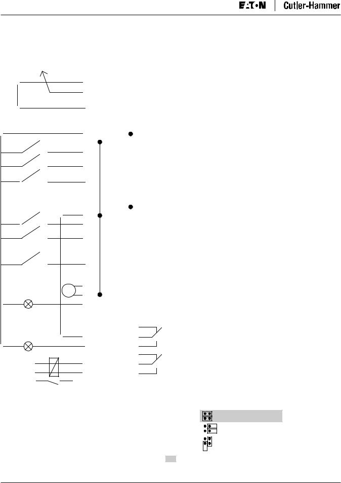
SPX9000 AF Drives
August 2005
Control I/O
Table 2-1: Standard Application Default I/O Configuration
Reference potentiometer |
Terminal |
Signal |
Description |
|
||||||||||||||||||||||||||
1 – 10 kΩ |
|
|
|
|
|
|
|
|
|
|||||||||||||||||||||
OPTA1 |
|
|
|
|
|
|
|
|||||||||||||||||||||||
|
|
|
|
|
|
|
|
|
|
|
|
|
|
|
|
|
|
|
|
|
|
|
|
|
|
|
|
|
||
|
|
|
|
|
|
|
|
|
|
|
|
|
|
|
|
|
|
|
|
|
|
1 |
|
+10Vref |
Reference output |
Voltage for potentiometer, etc. |
||||
|
|
|
|
|
|
|
|
|
|
|
|
|
|
|
|
|
|
|
|
|
|
|
||||||||
|
|
|
|
|
|
|
|
|
|
|
|
|
|
|
|
|
|
|
|
|
|
|
|
|
|
|
|
|
|
|
|
|
|
|
|
|
|
|
|
|
|
|
|
|
|
|
|
|
|
|
|
|
2 |
|
AI1+ |
Analog input, voltage range |
Voltage input frequency reference |
||||
|
|
|
|
|
|
|
|
|
|
|
|
|
|
|
|
|
|
|
|
|
|
|
||||||||
|
|
|
|
|
|
|
|
|
|
|
|
|
|
|
|
|
|
|
|
|
|
|
|
|
|
|
0 – 10V DC |
|
|
|
|
|
|
|
|
|
|
|
|
|
|
|
|
|
|
|
|
|
|
|
|
|
|
|
|
|
|
|
|
||
|
|
|
|
|
|
|
|
|
|
|
|
|
|
|
|
|
|
|
|
|
|
3 |
|
AI1- |
I/O Ground |
Ground for reference and controls |
||||
|
|
|
|
|
|
|
|
|
|
|
|
|
|
|
|
|
|
|
|
|
|
|
||||||||
|
|
|
|
|
|
|
|
|
|
|
|
|
|
|
|
|
|
|
|
|
|
|
||||||||
|
|
|
|
|
|
|
|
|
|
|
|
|
|
|
|
|
|
|
|
|
|
|
|
|
|
|
|
|
||
|
|
|
|
|
|
|
|
|
|
|
|
|
|
|
|
|
|
|
|
|
|
4 |
|
AI2+ |
Analog input, current range |
Current input frequency reference |
||||
|
|
|
|
|
|
|
|
|
|
|
|
|
|
|
|
|
|
|
|
|
|
|
|
|
|
|
0 – 20 mA |
|
|
|
|
|
|
|
|
|
|
|
|
|
|
|
|
|
|
|
|
|
|
|
|
|
5 |
|
AI2- |
|
|
|
|||
|
|
|
|
|
|
|
|
|
|
|
|
|
|
|
|
|
|
|
|
|
|
|
|
|
|
|
||||
|
|
|
|
|
|
|
|
|
|
|
|
|
|
|
|
|
|
|
|
|
|
|
|
|
|
|
|
|
||
|
|
|
|
|
|
|
|
|
|
|
|
|
|
|
|
|
|
|
|
|
|
6 |
|
+24V |
|
|
Control voltage output |
Voltage for switches, etc. max 0.1A |
||
|
|
|
|
|
|
|
|
|
|
|
|
|
|
|
|
|
|
|
|
|
|
7 |
|
GND |
|
|
I/O ground |
Ground for reference and controls |
||
|
|
|
|
|
|
|
|
|
|
|
|
|
|
|
|
|
|
|
|
|
|
|
|
|
|
|
|
|
||
|
|
|
|
|
|
|
|
|
|
|
|
|
|
|
|
|
|
|
|
|
|
8 |
|
DIN1 |
|
|
Start forward |
Contact closed = start forward |
||
|
|
|
|
|
|
|
|
|
|
|
|
|
|
|
|
|
|
|
|
|
|
|
|
|
||||||
|
|
|
|
|
|
|
|
|
|
|
|
|
|
|
|
|
|
|
|
|
|
|
|
|
|
|
(programmable) |
|
|
|
|
|
|
|
|
|
|
|
|
|
|
|
|
|
|
|
|
|
|
|
|
|
|
|
|
|
|
|
|
||
|
|
|
|
|
|
|
|
|
|
|
|
|
|
|
|
|
|
|
|
|
|
9 |
|
DIN2 |
|
|
Start reverse |
Contact closed = start reverse |
||
|
|
|
|
|
|
|
|
|
|
|
|
|
|
|
|
|
|
|
|
|
|
|
|
|
||||||
|
|
|
|
|
|
|
|
|
|
|
|
|
|
|
|
|
|
|
|
|
|
|
|
|
|
|
(programmable) |
|
|
|
|
|
|
|
|
|
|
|
|
|
|
|
|
|
|
|
|
|
|
|
|
|
|
|
|
|
|
|
|
||
|
|
|
|
|
|
|
|
|
|
|
|
|
|
|
|
|
|
|
|
|
|
10 |
|
DIN3 |
|
|
External fault input |
Contact open = no fault |
||
|
|
|
|
|
|
|
|
|
|
|
|
|
|
|
|
|
|
|
|
|
|
|
|
|
||||||
|
|
|
|
|
|
|
|
|
|
|
|
|
|
|
|
|
|
|
|
|
|
|
|
|
|
|
(programmable) |
Contact closed = fault |
||
|
|
|
|
|
|
|
|
|
|
|
|
|
|
|
|
|
|
|
|
|
|
|
|
|
|
|
|
|
||
|
|
|
|
|
|
|
|
|
|
|
|
|
|
|
|
|
|
|
|
|
|
11 |
|
CMA |
|
|
Common for DIN1 – DIN3 |
Connect to GND or +24V |
||
|
|
|
|
|
|
|
|
|
|
|
|
|
|
|
|
|
|
|
|
|
|
|
|
|
|
|
|
|
||
|
|
|
|
|
|
|
|
|
|
|
|
|
|
|
|
|
|
|
|
|
|
12 |
|
+24V |
|
|
Control voltage output |
Voltage for switches (see #6) |
||
|
|
|
|
|
|
|
|
|
|
|
|
|
|
|
|
|
|
|
|
|
|
|
|
|||||||
|
|
|
|
|
|
|
|
|
|
|
|
|
|
|
|
|
|
|
|
|
|
|
|
|
|
|
|
|
||
|
|
|
|
|
|
|
|
|
|
|
|
|
|
|
|
|
|
|
|
|
|
13 |
|
GND |
I/O ground |
Ground for reference and controls |
||||
|
|
|
|
|
|
|
|
|
|
|
|
|
|
|
|
|
|
|
|
|
|
|
|
|
|
|
|
|
|
|
|
|
|
|
|
|
|
|
|
|
|
|
|
|
|
|
|
|
|
|
|
|
14 |
|
DIN4 |
Multi-step speed select 1 |
DIN4 |
DIN5 |
Frequency ref. |
||
|
|
|
|
|
|
|
|
|
|
|
|
|
|
|
|
|
|
|
|
|
|
|
||||||||
|
|
|
|
|
|
|
|
|
|
|
|
|
|
|
|
|
|
|
|
|
|
|
|
|
|
|
|
|
|
|
|
|
|
|
|
|
|
|
|
|
|
|
|
|
|
|
|
|
|
|
|
|
15 |
|
DIN5 |
Multi-step speed select 2 |
Open |
Open |
Ref.Uin |
||
|
|
|
|
|
|
|
|
|
|
|
|
|
|
|
|
|
|
|
|
|
|
|
|
|
|
|
|
Closed |
Open |
Multi-step ref.1 |
|
|
|
|
|
|
|
|
|
|
|
|
|
|
|
|
|
|
|
|
|
|
|
|
|
|
|
|
|||
|
|
|
|
|
|
|
|
|
|
|
|
|
|
|
|
|
|
|
|
|
|
|
|
|
|
|
|
Open |
Closed |
Multi-step ref.2 |
|
|
|
|
|
|
|
|
|
|
|
|
|
|
|
|
|
|
|
|
|
|
|
|
|
|
|
|
Closed |
Closed |
Ref.Iin |
|
|
|
|
|
|
|
|
|
|
|
|
|
|
|
|
|
|
|
|
|
|
16 |
|
DIN6 |
Fault reset |
Contact open = no action |
||||
|
|
|
|
|
|
|
|
|
|
|
|
|
|
|
|
|
|
|
|
|
|
|
|
|
|
|
|
Contact closed = fault reset |
||
|
|
|
|
|
|
|
|
|
|
|
|
|
|
|
|
|
|
|
|
|
|
|
|
|
|
|
|
|
||
|
|
|
|
|
|
|
|
|
|
|
|
|
|
|
|
|
|
|
|
|
|
17 |
|
CMB |
Common for DIN4 – DIN6 |
Connect to GND or +24V |
||||
|
|
|
|
|
|
|
|
|
|
|
|
|
|
|
|
|
|
|
|
|
|
|
|
|
|
|
|
|
|
|
|
|
|
|
|
|
|
|
|
|
|
|
|
|
|
|
|
|
|
|
|
|
18 |
|
AO1+ |
Output frequency |
Programmable |
|
|||
|
|
|
|
|
|
|
|
|
|
|
|
|
|
|
mA |
|
|
|||||||||||||
|
|
|
|
|
|
|
|
|
|
|
|
|
|
|
|
|
|
|
|
Analog output |
Range 0 – 20 mA/RL, max. 500Ω |
|||||||||
19 |
|
AO1- |
||||||||||||||||||||||||||||
|
|
READY |
|
|
|
|
|
|
|
|||||||||||||||||||||
|
|
|
|
|||||||||||||||||||||||||||
|
|
|
|
|
|
|
|
|
|
|
|
|
|
|
|
|
|
|
|
|
|
20 |
|
DO1 |
Digital output |
Programmable |
|
|||
|
|
|
|
|
|
|
|
|
|
|
|
|
|
|
|
|
|
|
|
|
|
|
|
|||||||
|
|
|
|
|
|
|
|
|
|
|
|
|
|
|
|
|
|
|
|
|
|
|
|
|
|
|
READY |
Open collector, I ≤ 50 mA, U≤48 VDC |
||
|
|
|
|
|
|
|
|
|
|
|
|
|
|
|
|
|
|
|
|
|
|
|
|
|
|
|
|
|
|
|
|
|
|
|
|
|
|
|
|
|
|
|
|
|
|
|
|
|
|
|
|
|
OPTA2 |
|
|
|
|
|
|
|
|
|
|
|
|
|
|
|
|
|
|
|
|
|
|
|
|
|
|
|
|
|
|
21 |
|
RO1 |
Relay output 1 |
|
|
|
||
|
|
|
|
|
|
|
|
|
|
|
|
|
|
|
|
|
|
|
|
|
|
22 |
|
RO1 |
RUN |
|
|
|
||
|
|
|
|
|
|
|
|
|
|
|
|
|
|
|
|
|
|
|
|
|
|
|
|
|
|
|||||
|
|
|
|
RUN |
|
|
|
|
|
|||||||||||||||||||||
|
|
|
|
|
|
|
|
|
|
|
|
|
|
|
|
|
|
|
|
|
|
23 |
|
RO1 |
|
|
|
|
||
|
|
|
|
|
|
|
|
|
|
|
|
|
|
|
|
|
|
|
|
|
|
|
|
|
|
|
||||
|
|
|
|
|
|
|
|
|
|
|
|
|
|
|
|
|
|
|
|
|
|
|
|
|
|
|
||||
|
|
|
|
|
|
|
|
|
|
|
|
|
|
|
|
|
|
|
|
|
|
24 |
|
RO2 |
Relay output 2 |
|
|
|
||
|
220V |
|
|
|
|
|
|
|
|
|
|
|
|
|
|
|
|
25 |
|
RO2 |
FAULT |
|
|
|
||||||
|
|
|
|
|
|
|
|
|
|
|
|
|
|
|
|
|||||||||||||||
|
|
|
|
|
AC |
|
|
|
|
|
|
|
|
|
|
26 |
|
RO2 |
|
|
|
|
||||||||
|
|
|
|
|
|
|
|
|||||||||||||||||||||||
|
|
|
|
|
|
|
|
|
|
|
|
|
|
|
|
|
|
|
|
|
|
|
|
|
|
|
|
|
|
|
Note: For more information on jumper selections, see the SVX9000 AF Drives
User Manual, Chapter 4.
|
Jumper Block X3: |
|
|
CMA and CMB Grounding |
|
|
CMB connected to GND |
|
|
CMA connected to GND |
|
|
CMB isolated from GND |
|
|
CMA isolated from GND |
|
|
CMB and CMA internally connected |
|
|
together, isolated from GND |
|
|
= Factory default. |
|
2-2 |
For more information visit: www.EatonElectrical.com |
MN04004001E |
SPX9000 AF Drives
August 2005
Standard Application — Parameter Lists
On the next pages you will find the lists of parameters within the respective parameter groups. The parameter descriptions are given in Chapter 8. The descriptions are arranged according to the ID number of the parameter.
Column explanations:
Code |
= |
Location indication on the keypad; Shows the operator the present parameter |
|
|
number |
Parameter = |
Name of parameter |
|
Min |
= |
Minimum value of parameter |
Max |
= |
Maximum value of parameter |
Unit |
= |
Unit of parameter value; Given if available |
Default |
= |
Value preset by factory |
Cust |
= |
Customer’s own setting |
ID |
= |
ID number of the parameter |
= Parameter value can only be changed after the drive has been stopped.
= Use TTF method to program these parameters. See Page 6-3.
Monitoring Values (Control Keypad: Menu M7)
The monitoring values are the actual values of parameters and signals as well as statuses and measurements. Monitoring values cannot be edited.
See SVX9000 AF Drives User Manual, Chapter 5 for more information.
Table 2-2: Monitoring Values
Code |
Parameter |
Unit |
ID |
Description |
|
|
|
|
|
|
|
|
|
|
V1.1 |
Output frequency |
Hz |
1 |
Output frequency to motor |
|
|
|
|
|
V1.2 |
Frequency reference |
Hz |
25 |
Frequency reference to motor control |
|
|
|
|
|
V1.3 |
Motor speed |
rpm |
2 |
Motor speed in rpm |
|
|
|
|
|
V1.4 |
Motor current |
A |
3 |
|
|
|
|
|
|
V1.5 |
Motor torque |
% |
4 |
In % of the nominal motor torque |
|
|
|
|
|
V1.6 |
Motor power |
% |
5 |
Motor shaft power |
|
|
|
|
|
V1.7 |
Motor voltage |
V |
6 |
|
|
|
|
|
|
V1.8 |
DC Bus voltage |
V |
7 |
|
|
|
|
|
|
V1.9 |
Unit temperature |
°C |
8 |
Heatsink temperature |
|
|
|
|
|
V1.10 |
Motor temperature |
% |
9 |
Calculated motor temperature |
|
|
|
|
|
V1.11 |
Analog input 1 |
V |
13 |
AI1 |
|
|
|
|
|
V1.12 |
Analog input 2 |
mA |
14 |
AI2 |
|
|
|
|
|
V1.13 |
DIN1, DIN2, DIN3 |
|
15 |
Digital input statuses |
|
|
|
|
|
V1.14 |
DIN4, DIN5, DIN6 |
|
16 |
Digital input statuses |
|
|
|
|
|
V1.15 |
DO1, RO1, RO2 |
|
17 |
Digital and relay output statuses |
|
|
|
|
|
MN04004001E |
For more information visit: www.EatonElectrical.com |
2-3 |

SPX9000 AF Drives
|
|
|
|
|
|
|
|
|
|
|
|
|
|
|
|
August 2005 |
|
|
Table 2-2: Monitoring Values (Continued) |
|
|
|
|
|
|
||||||||
|
|
|
|
|
|
|
|
|
|
|
|
|
|
|
||
|
|
Code |
|
Parameter |
|
|
Unit |
|
ID |
Description |
||||||
|
|
|
|
|
|
|
|
|
|
|
|
|
|
|
|
|
|
|
|
|
|
|
|
|
|
|
|
|
|
|
|
|
|
|
|
V1.16 |
|
Analog Iout |
|
|
mA |
26 |
|
AO1 |
|
|
||||
|
|
M1.17 |
|
Monitoring items |
|
|
|
|
|
|
|
Displays three selectable monitoring |
||||
|
|
|
|
|
|
|
|
|
|
|
|
|
|
values |
|
|
|
|
|
|
|
|
|
|
|
|
|
|
|
|
|
|
|
Basic Parameters (Control Keypad: Menu M1 |
G1.1) |
|
|
|
|
|
|
|||||||||
Table 2-3: Basic Parameters — G1.1 |
|
|
|
|
|
|
|
|
|
|
|
|||||
|
|
|
|
|
|
|
|
|
|
|
|
|
||||
Code |
Parameter |
|
Min. |
Max. |
Unit |
|
Default |
|
Cust |
|
ID |
Note |
||||
|
|
|
|
|
|
|
|
|
|
|
|
|
|
|||
P1.1.1 |
Min frequency |
|
0.00 |
Par. 1.1.2 |
Hz |
|
0.00 |
|
|
|
101 |
|
|
|||
P1.1.2 |
Max frequency |
|
Par. |
320.00 |
Hz |
|
60.00 |
|
|
|
102 |
NOTE: If fmax > than the motor |
||||
|
|
|
|
|
1.1.1 |
|
|
|
|
|
|
|
|
|
synchronous speed, check |
|
|
|
|
|
|
|
|
|
|
|
|
|
|
|
|
suitability for motor and drive |
|
|
|
|
|
|
|
|
|
|
|
|
|
|
|
|
system. |
|
P1.1.3 |
Acceleration time 1 |
0.1 |
3000.0 |
s |
|
3.0 |
|
|
|
103 |
|
|
||||
P1.1.4 |
Deceleration time 1 |
0.1 |
3000.0 |
s |
|
3.0 |
|
|
|
104 |
|
|
||||
P1.1.5 |
Current limit |
|
0.4 x IH |
2 x IH |
A |
|
IL |
|
|
|
107 |
|
|
|||
P1.1.6 |
Nominal voltage of the |
180 |
690 |
V |
|
SPX2: |
|
|
|
110 |
|
|
||||
|
motor |
|
|
|
|
|
|
230V |
|
|
|
|
|
|
||
|
|
|
|
|
|
|
|
|
|
SPX4: |
|
|
|
|
|
|
|
|
|
|
|
|
|
|
|
|
460V |
|
|
|
|
|
|
|
|
|
|
|
|
|
|
|
|
SPX5: |
|
|
|
|
|
|
|
|
|
|
|
|
|
|
|
|
690V |
|
|
|
|
|
|
|
|
|
|
|
|
|
|
|
|
|
|
|||||
P1.1.7 |
Nominal frequency of |
30.00 |
320.00 |
Hz |
|
60.00 |
|
|
|
111 |
Check the rating plate of the |
|||||
|
the motor |
|
|
|
|
|
|
|
|
|
|
|
motor. |
|||
P1.1.8 |
Nominal speed of the |
300 |
20 000 |
rpm |
|
1720 |
|
|
|
112 |
The default applies for a 4-pole |
|||||
|
motor |
|
|
|
|
|
|
|
|
|
|
|
motor and a nominal size |
|||
|
|
|
|
|
|
|
|
|
|
|
|
|
|
|
frequency converter. |
|
|
|
|
|
|
|
|
|
|
|
|
|
|||||
P1.1.9 |
Nominal current of the |
0.4 x I |
2 x I |
A |
|
I |
|
|
|
113 |
Check the rating plate of the |
|||||
|
motor |
|
H |
H |
|
|
|
H |
|
|
|
|
motor. |
|||
|
|
|
|
|
|
|
|
|
|
|
|
|||||
|
|
|
|
|
|
|
|
|
|
|
|
|
|
|||
P1.1.10 |
Power Factor |
|
0.30 |
1.00 |
|
|
|
0.85 |
|
|
|
120 |
Check the rating plate of the |
|||
|
|
|
|
|
|
|
|
|
|
|
|
|
|
|
motor. |
|
|
|
|
|
|
|
|
|
|
|
|
|
|
|
|
||
P1.1.11 |
Local Control |
|
1 |
3 |
|
|
|
2 |
|
|
|
171 |
1 |
= I/O Terminal |
||
|
Place |
|
|
|
|
|
|
|
|
|
|
|
2 |
= Keypad |
||
|
|
|
|
|
|
|
|
|
|
|
|
|
|
|
3 |
= Fieldbus |
P1.1.12 |
Remote Control |
|
1 |
3 |
|
|
|
1 |
|
|
|
172 |
1 |
= I/O Terminal |
||
|
Place |
|
|
|
|
|
|
|
|
|
|
|
2 |
= Keypad |
||
|
|
|
|
|
|
|
|
|
|
|
|
|
|
|
3 |
= Fieldbus |
|
|
|
|
|
|
|
|
|
|
|
|
|
|
|
||
P1.1.13 |
Local reference |
|
0 |
3 |
|
|
|
2 |
|
|
|
173 |
0 |
= AI1 |
||
|
|
|
|
|
|
|
|
|
|
|
|
|
|
|
1 |
= AI2 |
|
|
|
|
|
|
|
|
|
|
|
|
|
|
|
2 |
= Keypad |
|
|
|
|
|
|
|
|
|
|
|
|
|
|
|
3 |
= Fieldbus |
|
|
|
|
|
|
|
|
|
|
|
|
|
|
|||
P1.1.14 |
Remote reference |
0 |
3 |
|
|
|
0 |
|
|
|
174 |
0 |
= AI1 |
|||
|
|
|
|
|
|
|
|
|
|
|
|
|
|
|
1 |
= AI2 |
|
|
|
|
|
|
|
|
|
|
|
|
|
|
|
2 |
= Keypad |
|
|
|
|
|
|
|
|
|
|
|
|
|
|
|
3 |
= Fieldbus |
|
|
|
|
|
|
|
|
|
|
|
|
|
||||
P1.1.15 |
Preset speed 1 |
|
0.00 |
Par. 1.1.2 |
Hz |
|
10.00 |
|
|
|
105 |
Speeds preset by operator. |
||||
P1.1.16 |
Preset speed 2 |
|
0.00 |
Par. 1.1.2 |
Hz |
|
60.00 |
|
|
|
106 |
|
|
|||
2-4 |
For more information visit: www.EatonElectrical.com |
MN04004001E |

SPX9000 AF Drives
August 2005
Input Signals (Control Keypad: Menu M1 |
G1.2) |
|
|
|
|
|
|
||||
Table 2-4: Input Signals — G1.2 |
|
|
|
|
|
|
|
|
|
||
|
|
|
|
|
|
|
|
|
|
||
Code |
Parameter |
Min. |
Max. |
Unit |
Default |
Cust |
ID |
Note |
|
||
|
|
|
|
|
|
|
|
|
|
|
|
P1.2.1 |
Start/Stop logic |
0 |
6 |
|
0 |
|
300 |
|
|
DIN1 |
DIN2 |
|
|
|
|
|
|
|
|
0 |
|
Start fwd |
Start rvs |
|
|
|
|
|
|
|
|
1 |
|
Start/Stop |
Rvs/Fwd |
|
|
|
|
|
|
|
|
2 |
|
Start/Stop |
Run enable |
|
|
|
|
|
|
|
|
3 |
|
Start pulse |
Stop pulse |
|
|
|
|
|
|
|
|
4 |
|
Fwd |
Rvs |
|
|
|
|
|
|
|
|
5 |
|
Start /Stop |
Rvs/Fwd |
|
|
|
|
|
|
|
|
6 |
|
Start /Stop |
Run enable |
P1.2.2 |
DIN3 function |
0 |
7 |
|
1 |
|
301 |
0 = Not used |
|
||
|
|
|
|
|
|
|
|
1 |
= Ext. fault. closing cont. |
||
|
|
|
|
|
|
|
|
2 |
= Ext. fault. opening cont. |
||
|
|
|
|
|
|
|
|
3 |
= Run enable |
|
|
|
|
|
|
|
|
|
|
4 |
= Acc./Dec. time select. |
||
|
|
|
|
|
|
|
|
5 |
= Force CP to Local |
||
|
|
|
|
|
|
|
|
6 |
= Force CP to Remote |
||
|
|
|
|
|
|
|
|
7 |
= Rvs (if par. 1.2.1 = 3) |
||
|
|
|
|
|
|
|
|
|
|
||
P1.2.3 |
Current reference |
0 |
1 |
|
1 |
|
302 |
0 = 0 – 20mA |
|
||
|
offset |
|
|
|
|
|
|
1 = 4 – 20mA |
|
||
|
|
|
|
|
|
|
|
|
|||
P1.2.4 |
Reference scaling |
0.00 |
Par. 1.2.5 |
Hz |
0.00 |
|
303 |
Selects the frequency that |
|||
|
minimum value |
|
|
|
|
|
|
corresponds to the min. |
|||
|
|
|
|
|
|
|
|
reference signal |
|
||
|
|
|
|
|
|
|
|
0.00 = No scaling |
|
||
|
|
|
|
|
|
|
|
|
|||
P1.2.5 |
Reference scaling |
0.00 |
320.00 |
Hz |
0.00 |
|
304 |
Selects the frequency that |
|||
|
maximum value |
|
|
|
|
|
|
corresponds to the max. |
|||
|
|
|
|
|
|
|
|
reference signal |
|
||
|
|
|
|
|
|
|
|
0.00 = No scaling |
|
||
|
|
|
|
|
|
|
|
|
|
||
P1.2.6 |
Reference inversion |
0 |
1 |
|
0 |
|
305 |
0 = Not inverted |
|
||
|
|
|
|
|
|
|
|
1 |
= Inverted |
|
|
P1.2.7 |
Reference filter time |
0.00 |
10.00 |
s |
0.10 |
|
306 |
0 = No filtering |
|
||
P1.2.8 |
AI1 signal selection |
|
|
|
A.1 |
|
377 |
TTF programming method used. |
|||
|
|
|
|
|
|
|
|
See Page 6-3. |
|
||
|
|
|
|
|
|
|
|
|
|||
P1.2.9 |
AI2 signal selection |
|
|
|
A.2 |
|
388 |
TTF programming method used. |
|||
|
|
|
|
|
|
|
|
See Page 6-3. |
|
||
|
|
|
|
|
|
|
|
|
|
|
|
Rising edge required to start. |
|
|
|
|
|
|
|
|
|
|
|
CP = control place. |
|
|
|
|
|
|
|
|
|
|
|
Output Signals (Control Keypad: Menu M1 G1.3) |
|
|
|
|
|
|
|||||
Table 2-5: Output Signals — G1.3 |
|
|
|
|
|
|
|
|
|
||
|
|
|
|
|
|
|
|
|
|
||
Code |
Parameter |
Min. |
Max. |
Unit |
Default |
Cust |
ID |
Note |
|
||
|
|
|
|
|
|
|
|
|
|||
P1.3.1 |
Analog output 1 signal |
0 |
|
|
A.1 |
|
464 |
TTF programming method used. |
|||
|
selection |
|
|
|
|
|
|
See Page 6-3. |
|
||
|
|
|
|
|
|
|
|
|
|
||
P1.3.2 |
Analog output |
0 |
8 |
|
1 |
|
307 |
0 = Not used |
|
||
|
function |
|
|
|
|
|
|
1 = Output freq. (0 – fmax) |
|||
|
|
|
|
|
|
|
|
2 |
= Freq. reference (0 – fmax) |
||
|
|
|
|
|
|
|
|
3 |
= Motor speed (0 – Motor |
||
|
|
|
|
|
|
|
|
nominal speed) |
|
||
|
|
|
|
|
|
|
|
4 |
= Motor current (0 – InMotor) |
||
|
|
|
|
|
|
|
|
5 |
= Motor torque (0 – TnMotor) |
||
|
|
|
|
|
|
|
|
6 |
= Motor power (0 – PnMotor) |
||
|
|
|
|
|
|
|
|
7 |
= Motor voltage (0 – UnMotor) |
||
|
|
|
|
|
|
|
|
8 |
= DC-Bus volt (0 – 1000V) |
||
P1.3.3 |
Analog output filter |
0.00 |
10.00 |
s |
1.00 |
|
308 |
0 = No filtering |
|
||
|
time |
|
|
|
|
|
|
|
|
|
|
|
|
|
|
|
|
|
|
|
|
|
|
MN04004001E |
For more information visit: www.EatonElectrical.com |
2-5 |

SPX9000 AF Drives
August 2005
Table 2-5: Output Signals — G1.3 (Continued)
Code |
Parameter |
Min. |
Max. |
Unit |
Default |
Cust |
ID |
Note |
|
|
|
|
|
|
|
|
|
|
|
P1.3.4 |
Analog output |
0 |
1 |
|
0 |
|
309 |
0 |
= Not inverted |
|
inversion |
|
|
|
|
|
|
1 |
= Inverted |
P1.3.5 |
Analog output |
0 |
1 |
|
0 |
|
310 |
0 |
= 0 mA |
|
minimum |
|
|
|
|
|
|
1 |
= 4 mA |
|
|
|
|
|
|
|
|
|
|
P1.3.6 |
Analog output scale |
10 |
1000 |
% |
100 |
|
311 |
|
|
P1.3.7 |
Digital output 1 |
0 |
16 |
|
1 |
|
312 |
0 |
= Not used |
|
function |
|
|
|
|
|
|
1 |
= Ready |
|
|
|
|
|
|
|
|
2 |
= Run |
|
|
|
|
|
|
|
|
3 |
= Fault |
|
|
|
|
|
|
|
|
4 |
= Fault inverted |
|
|
|
|
|
|
|
|
5 |
= FC overheat warning |
|
|
|
|
|
|
|
|
6 |
= Ext. fault or warning |
|
|
|
|
|
|
|
|
7 |
= Ref. fault or warning |
|
|
|
|
|
|
|
|
8 |
= Warning |
|
|
|
|
|
|
|
|
9 |
= Reversed |
|
|
|
|
|
|
|
|
10 = Preset speed 1 |
|
|
|
|
|
|
|
|
|
11 = At speed |
|
|
|
|
|
|
|
|
|
12 = Mot. regulator active |
|
|
|
|
|
|
|
|
|
13 = OP freq. limit 1 superv. |
|
|
|
|
|
|
|
|
|
14 = Remote Control Active |
|
|
|
|
|
|
|
|
|
15 = Thermistor fault/warng |
|
|
|
|
|
|
|
|
|
16 = Fieldbus input data |
|
|
|
|
|
|
|
|
|
|
|
P1.3.8 |
Relay output 1 |
0 |
16 |
|
2 |
|
313 |
Same as parameter 1.3.7 |
|
|
function |
|
|
|
|
|
|
|
|
P1.3.9 |
Relay output 2 |
0 |
16 |
|
3 |
|
314 |
Same as parameter 1.3.7 |
|
|
function |
|
|
|
|
|
|
|
|
|
|
|
|
|
|
|
|
|
|
P1.3.10 |
Output frequency limit |
0 |
2 |
|
0 |
|
315 |
0 |
= No limit |
|
1 supervision |
|
|
|
|
|
|
1 |
= Low limit supervision |
|
|
|
|
|
|
|
|
2 |
= High limit supervision |
P1.3.11 |
Output frequency limit |
0.00 |
320.00 |
Hz |
0.00 |
|
316 |
|
|
|
1; Supervised value |
|
|
|
|
|
|
|
|
|
|
|
|
|
|
|
|
|
|
P1.3.12 |
Analog output 2 signal |
0 |
|
|
0.1 |
|
471 |
TTF programming method used. |
|
|
selection |
|
|
|
|
|
|
See Page 6-3. |
|
|
|
|
|
|
|
|
|
|
|
P1.3.13 |
Analog output 2 |
0 |
8 |
|
4 |
|
472 |
Same as parameter 1.3.2 |
|
|
function |
|
|
|
|
|
|
|
|
P1.3.14 |
Analog output 2 filter |
0.00 |
10.00 |
s |
1.00 |
|
473 |
0 |
= No filtering |
|
time |
|
|
|
|
|
|
|
|
|
|
|
|
|
|
|
|
|
|
P1.3.15 |
Analog output 2 |
0 |
1 |
|
0 |
|
474 |
0 |
= Not inverted |
|
inversion |
|
|
|
|
|
|
1 |
= Inverted |
|
|
|
|
|
|
|
|
|
|
P1.3.16 |
Analog output 2 |
0 |
1 |
|
0 |
|
475 |
0 |
= 0 mA |
|
minimum |
|
|
|
|
|
|
1 |
= 4 mA |
P1.3.17 |
Analog output 2 |
10 |
1000 |
% |
100 |
|
476 |
|
|
|
scaling |
|
|
|
|
|
|
|
|
|
|
|
|
|
|
|
|
|
|
2-6 |
For more information visit: www.EatonElectrical.com |
MN04004001E |

SPX9000 AF Drives
August 2005
Drive Control Parameters (Control Keypad: Menu M1 |
G1.4) |
|
|
||||||
Table 2-6: Drive Control Parameters — G1.4 |
|
|
|
|
|
|
|||
|
|
|
|
|
|
|
|
|
|
Code |
Parameter |
Min. |
Max. |
Unit |
Default |
Cust |
ID |
Note |
|
|
|
|
|
|
|
|
|
|
|
P1.4.1 |
Ramp 1 shape |
0.0 |
10.0 |
s |
0.0 |
|
500 |
0 |
= Linear |
|
|
|
|
|
|
|
|
>0 = S-curve ramp time |
|
|
|
|
|
|
|
|
|
|
|
P1.4.2 |
Ramp 2 shape |
0.0 |
10.0 |
s |
0.0 |
|
501 |
0 |
= Linear |
|
|
|
|
|
|
|
|
>0 = S-curve ramp time |
|
P1.4.3 |
Acceleration time 2 |
0.1 |
3000.0 |
s |
10.0 |
|
502 |
|
|
P1.4.4 |
Deceleration time 2 |
0.1 |
3000.0 |
s |
10.0 |
|
503 |
|
|
P1.4.5 |
Brake chopper |
0 |
4 |
|
0 |
|
504 |
0 |
= Disabled |
|
|
|
|
|
|
|
|
1 |
= Used when running |
|
|
|
|
|
|
|
|
2 |
= External brake chopper |
|
|
|
|
|
|
|
|
3 |
= Used when stopped/running |
|
|
|
|
|
|
|
|
4 |
= Used when running (no testing) |
|
|
|
|
|
|
|
|
|
|
P1.4.6 |
Start function |
0 |
1 |
|
0 |
|
505 |
0 |
= Ramp |
|
|
|
|
|
|
|
|
1 |
= Flying start |
|
|
|
|
|
|
|
|
|
|
P1.4.7 |
Stop function |
0 |
3 |
|
1 |
|
506 |
0 |
= Coasting |
|
|
|
|
|
|
|
|
1 |
= Ramp |
|
|
|
|
|
|
|
|
2 |
= Ramp+Run enable coast |
|
|
|
|
|
|
|
|
3 |
= Coast+Run enable ramp |
|
|
|
|
|
|
|
|
|
|
P1.4.8 |
DC braking current |
0.4 x IH |
2 x IH |
A |
IH |
|
507 |
|
|
P1.4.9 |
DC braking time at |
0.00 |
600.00 |
s |
0.00 |
|
508 |
0 |
= DC brake is off at stop |
|
stop |
|
|
|
|
|
|
|
|
P1.4.10 |
Frequency to start DC |
0.10 |
10.00 |
Hz |
1.50 |
|
515 |
|
|
|
braking during |
|
|
|
|
|
|
|
|
|
ramp stop |
|
|
|
|
|
|
|
|
|
|
|
|
|
|
|
|
|
|
P1.4.11 |
DC braking time |
0.00 |
600.00 |
s |
0.00 |
|
516 |
0 |
= DC brake is off at start |
|
at start |
|
|
|
|
|
|
|
|
P1.4.12 |
Flux brake |
0 |
1 |
|
0 |
|
520 |
0 |
= Off |
|
|
|
|
|
|
|
|
1 |
= On |
|
|
|
|
|
|
|
|
|
|
P1.4.13 |
Flux braking current |
0.4 x IH |
2 x IH |
A |
IH |
|
519 |
|
|
Prohibit Frequency Parameters (Control Keypad: Menu M1 |
G1.5) |
|
|||||||
Table 2-7: Prohibit Frequency Parameters — G1.5 |
|
|
|
|
|
||||
|
|
|
|
|
|
|
|
|
|
Code |
Parameter |
Min. |
Max. |
Unit |
Default |
Cust |
|
ID |
Note |
|
|
|
|
|
|
|
|
|
|
P1.5.1 |
Prohibit frequency |
0.00 |
Par. 1.5.2 |
Hz |
0.00 |
|
|
509 |
|
|
range 1 low limit |
|
|
|
|
|
|
|
|
|
|
|
|
|
|
|
|
|
|
P1.5.2 |
Prohibit frequency |
0.00 |
320.00 |
Hz |
0.0 |
|
|
510 |
|
|
range 1 high limit |
|
|
|
|
|
|
|
|
|
|
|
|
|
|
|
|
|
|
P1.5.3 |
Prohibit acc./dec. ramp |
0.1 |
10.0 |
|
1.0 |
|
|
518 |
|
MN04004001E |
For more information visit: www.EatonElectrical.com |
2-7 |

SPX9000 AF Drives
August 2005
Motor Control Parameters (Control Keypad: Menu M1 G1.6)
Table 2-8: Motor Control Parameters — G1.6
Code |
Parameter |
Min. |
Max. |
Unit |
Default |
Cust |
ID |
Note |
|
|
|
|
|
|
|
|
|
|
|
P1.6.1 |
Motor control mode |
0 |
1/6 |
|
0 |
|
600 |
SVX: |
|
|
|
|
|
|
|
|
|
0 |
= Frequency control |
|
|
|
|
|
|
|
|
1 |
= Speed control |
|
|
|
|
|
|
|
|
Additionally for SPX: |
|
|
|
|
|
|
|
|
|
2 |
= Torque control |
|
|
|
|
|
|
|
|
3 |
= Closed loop speed ctrl |
|
|
|
|
|
|
|
|
4 |
= Closed loop torque ctrl |
|
|
|
|
|
|
|
|
5 |
= Adv. open loop freq. control |
|
|
|
|
|
|
|
|
6 |
= Advanced open loop speed |
|
|
|
|
|
|
|
|
control |
|
P1.6.2 |
V/Hz optimization |
0 |
1 |
|
0 |
|
109 |
0 |
= Not used |
|
|
|
|
|
|
|
|
1 |
= Automatic torque boost |
|
|
|
|
|
|
|
|
|
|
P1.6.3 |
V/Hz ratio selection |
0 |
3 |
|
0 |
|
108 |
0 |
= Linear |
|
|
|
|
|
|
|
|
1 |
= Squared |
|
|
|
|
|
|
|
|
2 |
= Programmable |
|
|
|
|
|
|
|
|
3 |
= Linear with flux optim. |
|
|
|
|
|
|
|
|
|
|
P1.6.4 |
Field weakening point |
8.00 |
320.00 |
Hz |
60.00 |
|
602 |
|
|
P1.6.5 |
Voltage at field |
10.00 |
200.00 |
% |
100.00 |
|
603 |
n% x U |
|
|
weakening point |
|
|
|
|
|
|
|
nmot |
|
|
|
|
|
|
|
|
|
|
|
|
|
|
|
|
|
|
|
|
P1.6.6 |
V/Hz curve midpoint |
0.00 |
Par. 1.6.4 |
Hz |
60.00 |
|
604 |
|
|
|
frequency |
|
|
|
|
|
|
|
|
P1.6.7 |
V/Hz curve midpoint |
0.00 |
100.00 |
% |
100.00 |
|
605 |
n% x U |
|
|
voltage |
|
|
|
|
|
|
|
nmot |
|
|
|
|
|
|
|
Parameter max. value = |
||
|
|
|
|
|
|
|
|
par. 2.6.5 |
|
|
|
|
|
|
|
|
|
|
|
P1.6.8 |
Output voltage at zero |
0.00 |
40.00 |
% |
0.00 |
|
606 |
n% x U |
|
|
frequency |
|
|
|
|
|
|
|
nmot |
|
|
|
|
|
|
|
|
|
|
|
|
|
|
|
|
|
|
|
|
P1.6.9 |
Switching frequency |
1.0 |
Varies |
kHz |
Varies |
|
601 |
See Table 8-12 on Page 8-57 for |
|
|
|
|
|
|
|
|
|
exact values |
|
|
|
|
|
|
|
|
|
|
|
P1.6.10 |
Overvoltage controller |
0 |
2 |
|
1 |
|
607 |
0 |
= Not used |
|
|
|
|
|
|
|
|
1 |
= Used (no ramping) |
|
|
|
|
|
|
|
|
2 |
= Used (ramping) |
P1.6.11 |
Undervoltage |
0 |
1 |
|
1 |
|
608 |
0 |
= Not used |
|
controller |
|
|
|
|
|
|
1 |
= Used |
|
|
|
|
|
|
|
|
|
|
P1.6.12 |
Load Drooping |
0.00 |
100.00 |
|
0.01 |
|
620 |
Drooping % of nominal speed at |
|
|
|
|
|
|
|
|
|
nominal torque |
|
|
|
|
|
|
|
|
|
|
|
P1.6.13 |
Identification |
0 |
1 |
|
0 |
|
631 |
0 |
= Not used |
|
|
|
|
|
|
|
|
1 |
= Used |
Closed Loop |
parameter group 1.6.14 (SPX |
only) |
|
|
|
|
|
|
|
P1.6.14.1 |
Magnetizing current |
0.00 |
100.00 |
A |
0.00 |
|
612 |
|
|
P1.6.14.2 |
Speed control P gain |
0 |
1000 |
|
30 |
|
613 |
|
|
P1.6.14.3 |
Speed control I time |
0.0 |
500.0 |
ms |
30.0 |
|
614 |
|
|
P1.6.14.4 |
Load drooping |
0.00 |
100.00 |
% |
0.00 |
|
620 |
|
|
P1.6.14.5 |
Acceleration |
0.00 |
300.00 |
s |
0.00 |
|
626 |
|
|
|
compensation |
|
|
|
|
|
|
|
|
|
|
|
|
|
|
|
|
|
|
P1.6.14.6 |
Slip adjust |
0 |
500 |
% |
100 |
|
619 |
|
|
P1.6.14.7 |
Magnetizing current at |
MotCurr |
MotCurr |
A |
0.00 |
|
627 |
|
|
|
start |
Min |
Max |
|
|
|
|
|
|
|
|
|
|
|
|
|
|
|
|
P1.6.14.8 |
Magnetizing time at |
0.0 |
600.0 |
s |
0.0 |
|
628 |
|
|
|
start |
|
|
|
|
|
|
|
|
2-8 |
For more information visit: www.EatonElectrical.com |
MN04004001E |

SPX9000 AF Drives
August 2005
Table 2-8: Motor Control Parameters — G1.6
Code |
Parameter |
Min. |
Max. |
Unit |
Default |
Cust |
ID |
Note |
Closed Loop |
parameter group 1.6.14 (SPX |
only) (Continued) |
|
|
|
|
|
|
P1.6.14.9 |
0-speed time at start |
0 |
32000 |
ms |
100 |
|
615 |
|
P1.6.14.10 |
0-speed time at stop |
0 |
32000 |
ms |
100 |
|
616 |
|
P1.6.14.11 |
Start-up torque |
0 |
3 |
|
0 |
|
621 |
0 = Not used |
|
|
|
|
|
|
|
|
1 = Torque memory |
|
|
|
|
|
|
|
|
2 = Torque reference |
|
|
|
|
|
|
|
|
3 = Start-up torque fwd/rev |
|
|
|
|
|
|
|
|
|
P1.6.14.12 |
Start-up torque FWD |
-300.0 |
300.0 |
s |
0.0 |
|
633 |
|
P1.6.14.13 |
Start-up torque REV |
-300.0 |
300.0 |
s |
0.0 |
|
634 |
|
P1.6.14.15 |
Encoder filter time |
0 |
1000 |
ms |
0 |
|
618 |
|
P1.6.14.17 |
Current control |
0.00 |
100.00 |
% |
40.00 |
|
617 |
|
|
P gain |
|
|
|
|
|
|
|
|
|
|
|
|
|
|
|
|
Advanced Open Loop parameter group 1.6.15 (SPX only) |
|
|
|
|
|
|||
P1.6.15.1 |
Zero speed current |
0.0 |
250.0 |
% |
120.0 |
|
625 |
|
P1.6.15.2 |
Minimum current |
0.0 |
100.0 |
% |
80.0 |
|
622 |
|
P1.6.15.3 |
Flux reference |
0.0 |
100.0 |
% |
80.0 |
|
623 |
|
P1.6.15.4 |
Frequency limit |
0.0 |
100.0 |
% |
20.0 |
|
635 |
|
P1.6.15.5 |
V/Hz boost |
0 |
1 |
|
0 |
|
632 |
|
Protections (Control Keypad: Menu M1 |
G1.7) |
|
|
|
|
|
||||
Table 2-9: Protections — G1.7 |
|
|
|
|
|
|
|
|
|
|
|
|
|
|
|
|
|
|
|
|
|
Code |
Parameter |
Min. |
Max. |
|
Unit |
Default |
Cust |
ID |
Note |
|
|
|
|
|
|
|
|
|
|
|
|
P1.7.1 |
Response to 4 mA |
0 |
5 |
|
|
0 |
|
700 |
0 |
= No response |
|
reference fault |
|
|
|
|
|
|
|
1 |
= Warning |
|
|
|
|
|
|
|
|
|
2 |
= Warning+Previous Freq. |
|
|
|
|
|
|
|
|
|
3 |
= Wrng+PresetFreq 1.7.2 |
|
|
|
|
|
|
|
|
|
4 |
= Fault.stop acc. to 1.4.7 |
|
|
|
|
|
|
|
|
|
5 |
= Fault.stop by coasting |
P1.7.2 |
4 mA reference fault |
0.00 |
Par. 1.1.2 |
Hz |
0.00 |
|
728 |
|
|
|
|
frequency |
|
|
|
|
|
|
|
|
|
|
|
|
|
|
|
|
|
|
|
|
P1.7.3 |
Response to external |
0 |
3 |
|
|
2 |
|
701 |
0 |
= No response |
|
fault |
|
|
|
|
|
|
|
1 |
= Warning |
|
|
|
|
|
|
|
|
|
2 |
= Fault.stop acc. to 1.4.7 |
P1.7.4 |
Input phase |
0 |
3 |
|
|
0 |
|
730 |
||
|
supervision |
|
|
|
|
|
|
|
3 |
= Fault.stop by coasting |
|
|
|
|
|
|
|
|
|
|
|
P1.7.5 |
Response to |
1 |
3 |
|
|
2 |
|
727 |
|
|
|
undervoltage fault |
|
|
|
|
|
|
|
|
|
|
|
|
|
|
|
|
|
|
|
|
P1.7.6 |
Output phase |
0 |
3 |
|
|
2 |
|
702 |
|
|
|
supervision |
|
|
|
|
|
|
|
|
|
|
|
|
|
|
|
|
|
|
|
|
P1.7.7 |
Earth fault protection |
0 |
3 |
|
|
2 |
|
703 |
|
|
P1.7.8 |
Thermal protection of |
0 |
3 |
|
|
2 |
|
704 |
|
|
|
the motor |
|
|
|
|
|
|
|
|
|
P1.7.9 |
Motor ambient |
-100.0 |
100.0 |
|
% |
0.0 |
|
705 |
|
|
|
temperature factor |
|
|
|
|
|
|
|
|
|
|
|
|
|
|
|
|
|
|
|
|
P1.7.10 |
Motor cooling factor at |
0.0 |
150.0 |
|
% |
40.0 |
|
706 |
|
|
|
zero speed |
|
|
|
|
|
|
|
|
|
|
|
|
|
|
|
|
|
|
|
|
P1.7.11 |
Motor thermal time |
1 |
200 |
|
min |
45 |
|
707 |
|
|
|
constant |
|
|
|
|
|
|
|
|
|
P1.7.12 |
Motor duty cycle |
0 |
100 |
|
% |
100 |
|
708 |
|
|
P1.7.13 |
Stall protection |
0 |
3 |
|
|
0 |
|
709 |
0 |
= No response |
|
|
|
|
|
|
|
|
|
1 |
= Warning |
|
|
|
|
|
|
|
|
|
2 |
= Fault.stop acc. to 1.4.7 |
|
|
|
|
|
|
|
|
|
3 |
= Fault.stop by coasting |
MN04004001E |
For more information visit: www.EatonElectrical.com |
2-9 |

SPX9000 AF Drives
August 2005
Table 2-9: Protections — G1.7 (Continued)
Code |
Parameter |
Min. |
Max. |
Unit |
Default |
Cust |
ID |
Note |
|
|
|
|
|
|
|
|
|
|
|
P1.7.14 |
Stall current |
0.1 |
InMotor |
A |
IL |
|
710 |
|
|
|
|
|
x 2 |
|
|
|
|
|
|
P1.7.15 |
Stall time limit |
1.00 |
120.00 |
s |
15.00 |
|
711 |
|
|
P1.7.16 |
Stall frequency limit |
1.0 |
Par. |
Hz |
25.0 |
|
712 |
|
|
|
|
|
1.1.2 |
|
|
|
|
|
|
|
|
|
|
|
|
|
|
|
|
P1.7.17 |
Underload protection |
0 |
3 |
|
0 |
|
713 |
0 |
= No response |
|
|
|
|
|
|
|
|
1 |
= Warning |
|
|
|
|
|
|
|
|
2 |
= Fault.stop acc. to 1.4.7 |
|
|
|
|
|
|
|
|
3 |
= Fault.stop by coasting |
|
|
|
|
|
|
|
|
|
|
P1.7.18 |
Field weakening area |
10 |
150 |
% |
50 |
|
714 |
|
|
|
load |
|
|
|
|
|
|
|
|
|
|
|
|
|
|
|
|
|
|
P1.7.19 |
Zero frequency load |
5.0 |
150.0 |
% |
10.0 |
|
715 |
|
|
P1.7.20 |
Underload protection |
2 |
600 |
s |
20 |
|
716 |
|
|
|
time limit |
|
|
|
|
|
|
|
|
P1.7.21 |
Response to |
0 |
3 |
|
2 |
|
732 |
0 |
= No response |
|
thermistor fault |
|
|
|
|
|
|
1 |
= Warning |
|
|
|
|
|
|
|
|
2 |
= Fault.stop acc. to 1.4.7 |
|
|
|
|
|
|
|
|
3 |
= Fault.stop by coasting |
P1.7.22 |
Response to fieldbus |
0 |
3 |
|
2 |
|
733 |
See P1.7.21 |
|
|
fault |
|
|
|
|
|
|
|
|
|
|
|
|
|
|
|
|
|
|
P1.7.23 |
Response to slot fault |
0 |
3 |
|
2 |
|
734 |
See P1.7.21 |
|
Autorestart Parameters (Control Keypad: Menu M1 |
G1.8) |
|
||||||
Table 2-10: Autorestart Parameters — G1.8 |
|
|
|
|
|
|||
|
|
|
|
|
|
|
|
|
Code |
Parameter |
Min. |
Max. |
Unit |
Default |
Cust |
ID |
Note |
|
|
|
|
|
|
|
|
|
P1.8.1 |
Wait time |
0.10 |
10.00 |
s |
0.50 |
|
717 |
|
P1.8.2 |
Trial time |
0.00 |
60.00 |
s |
30.00 |
|
718 |
|
P1.8.3 |
Start function |
0 |
2 |
|
0 |
|
719 |
0 = Ramp |
|
|
|
|
|
|
|
|
1 = Flying start |
|
|
|
|
|
|
|
|
2 = According to par. 1.4.6 |
|
|
|
|
|
|
|
|
|
P1.8.4 |
Number of tries after |
0 |
10 |
|
0 |
|
720 |
|
|
undervoltage trip |
|
|
|
|
|
|
|
P1.8.5 |
Number of tries after |
0 |
10 |
|
0 |
|
721 |
|
|
overvoltage trip |
|
|
|
|
|
|
|
|
|
|
|
|
|
|
|
|
P1.8.6 |
Number of tries after |
0 |
3 |
|
0 |
|
722 |
|
|
overcurrent trip |
|
|
|
|
|
|
|
|
|
|
|
|
|
|
|
|
P1.8.7 |
Number of tries after |
0 |
10 |
|
0 |
|
723 |
|
|
reference trip |
|
|
|
|
|
|
|
P1.8.8 |
Number of tries after |
0 |
10 |
|
0 |
|
726 |
|
|
motor temperature |
|
|
|
|
|
|
|
|
fault trip |
|
|
|
|
|
|
|
|
|
|
|
|
|
|
|
|
P1.8.9 |
Number of tries after |
0 |
10 |
|
0 |
|
725 |
|
|
external fault trip |
|
|
|
|
|
|
|
P1.8.10 |
Number of tries after |
0 |
10 |
|
1 |
|
738 |
|
|
underload fault trip |
|
|
|
|
|
|
|
|
|
|
|
|
|
|
|
|
2-10 |
For more information visit: www.EatonElectrical.com |
MN04004001E |

SPX9000 AF Drives
August 2005
Keypad Control (Control Keypad: Menu M2)
The parameters for the selection of control place and direction on the keypad are listed below. See the Keypad control menu in the SVX9000 AF Drives User Manual.
Table 2-11: Keypad Control Parameters — M2
Code |
Parameter |
Min. |
Max. |
Unit |
Default |
Cust |
ID |
Note |
|
|
|
|
|
|
|
|
|
|
|
R2.1 |
Keypad reference |
Par. 1.1.1 |
Par. 1.1.2 |
Hz |
|
|
|
|
|
P1.2 |
Direction (on keypad) |
0 |
1 |
|
0 |
|
123 |
0 |
= Forward |
|
|
|
|
|
|
|
|
1 |
= Reverse |
|
|
|
|
|
|
|
|
|
|
R2.3 |
Stop button |
0 |
1 |
|
1 |
|
114 |
0 |
= Limited function of Stop button |
|
|
|
|
|
|
|
|
1 |
= Stop button always enabled |
System Menu (Control Keypad: Menu M5)
For parameters and functions related to the general use of the drive, such as application and language selection, customized parameter sets or information about the hardware and software, see Chapter 5 in the SVX9000 AF Drives User Manual.
Expander Boards (Control Keypad: Menu M6)
The M6 menu shows the expander and option boards attached to the control board and board-related information. For more information, see Chapter 5 in the SVX9000 AF Drives User Manual.
MN04004001E |
For more information visit: www.EatonElectrical.com |
2-11 |

SPX9000 AF Drives
August 2005
2-12 |
For more information visit: www.EatonElectrical.com |
MN04004001E |
 Loading...