


w w w. e a to n . c o m
Ellipse PRO
650/850/1200/1600
Installation and user manual
English - Français
Deutsch - Italiano Español - Nederlands Português - Eλληνiκά
Polski - Česky
Solvenčina - Slovensko
Magyar -Türkçe
РУCCКИЙ
Svenska - Suomi
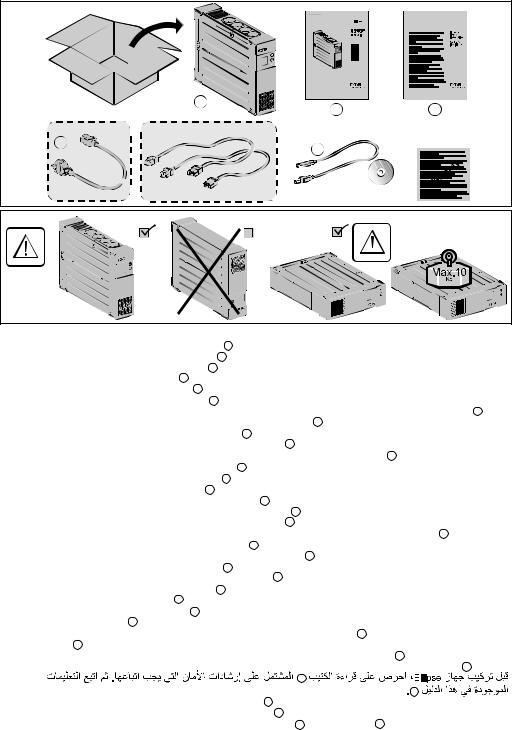
Packaging
1 |
2 |
3 |
|
FR / DIN models |
IEC |
4
Caution!
EN • Before installing the Ellipse, read the booklet 3 containing the safety instructions that must be followed.Then follow the instructions given in this manual 2 .
FR • Avant l'installation de Ellipse, lire le livret 3 qui présente les consignes de sécurité à respecter. Suivre ensuite les instructions du présent manuel 2 .
DE • Vor Installation des Ellipse die im Heft 3 genannten Sicherheitsvorschriften lesen. Anschließend die Anweisungen im vorliegenden Handbuch 2 befolgen.
IT • Prima dell’installazione del Ellipse, leggere attentamente le istruzioni di sicurezza riportate sul libretto 3 . In seguito, attenersi alle istruzioni riportate sul presente manuale 2 .
ES • Antes de la instalación del Ellipse, leer el manual 3 que presenta las instrucciones de seguridad a cumplir. A continuación, seguir las instrucciones del presente manual 2 .
NL • Lees voordat u het Ellipse gaat installeren eerst de veiligheidsinstructies in boekje 3 . Volg daarna de instructies van deze handleiding 2 .
PT • Antes da instalação do Ellipse, ler o caderno 3 onde constam as instruções de segurança a respeitar. Depois, seguir as instruções do presente manual 2 .
EL ••Πριν την εγικατάσταση του Ellipse, διαβάστε το φυλλάδιο 3 με τις συβουλές ασφαλείας που πρέπει να τηρείτε. Στη συνέχεια, ακολουθήστε τις οδηγίες χρήσης αυτού του φυλλαδίου 2 .
PL • Przed zainstalowaniem Ellipse, należy przeczytać instrukcję 3 , która zawiera niezbędne zalecenia bezpieczeństwa. Następnie należy zapoznać się z zaleceniami zawartymi w niniejszej instrukcji 2 .
CS • Před instatací zdroje Ellipse si prostudujte příručku 3 kde najdete bezpečnostní předpisy, které je třeba dodržovat. Dále postupujte podle pokynů uvedených v příručce 2 .
SL • Pred inštaláciou výpustky si prečítajte knižku 3 , v ktorej sú uvedené bezpečnostné príkazy, ktoré je potrebné dodržať. Potom postupujte podľa pokynov tejto príručky 2 .
SK • Preden instalirate Ellipse, preberite knjižico 3 , v kateri so varnostna navodila, ki jih je treba upoštevati. Nato sledite navodilom tega priročnika 2 .
HU • Az Ellipse telepítése előtt olvassa el a 3 -es könyvet, mely a betartandó biztonsági előirásokat tartalmazza. Ezután kövesse a jelen, 2 -ös kezikönyv utasításait.
TR • Ellipse'in tesisatini yapmadan önce, uyulacakgüvenliktalimatlarini gösteren 3 sayili kitapçiği okuyunuz. Dana sonra isbu 2 sayili ei kitabindaki talimatlara uyunuz.
RU • Перед установкой Источника Бесперебойного Питания (ASI) прочитайте инструкцию 3 с правилами пo технике
AR |
безопасности, которые необходимо соблюдать. Затем следуйте указаниям настоящего руководства 2 . |
3 |
|
|
2 |
SV • Innan installation av Ellipse, läs instruktionsmanualen 3 innehållande säkerhetsinstruktionerna och följ sedan dem. Följ sedan instruktionerna som ges i denna manua 2 .
FI • Lue nämä ohjeet ennen Ellipse asennusta turvallisuusohjeet 3 ja käyttöohjeet 2 .
2 |
614-06817-00 |

Quick start |
|
|
A |
FR / DIN |
IEC |
B |
|
|
|
650 / 850 |
1200 / 1600 |
In
Internet
Modem
Out |
k / Networ
EcoControl Master


C |
5 |
614-06817-00 |
D |
Register warranty at: powerquality.eaton.com
3
Battery disposal and safety
•Caution. Battery service life is reduced by 50 % for every ten degrees above 25 °C.
•The battery must be replaced exclusively by qualified personnel (risk of shock), with new battery approved by Eaton to ensure correct operation of the UPS.
•The battery must be disposed of in accordance with applicable regulations.To remove the battery, shut down the UPS (button 6 OFF), remove the power cord and proceed as indicated below "Battery change".
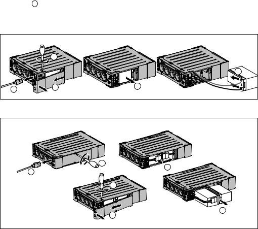
Battery change
650 / 850 |
|
|
|
b |
|
|
|
e |
a |
c |
d |
•Warning: take care not to inverse the polarity + (red) and - (black) when connecting the battery as this will destroy the device.
1200 / 1600
b |
a |
c |
f
d
4 |
614-06817-00 |

Technical characteristics
Ellipse PRO |
650 |
|
850 |
|
1200 |
|
1600 |
• UPS power |
650 VA / |
|
850 VA / |
|
1200 VA / |
|
1600 VA / |
|
|
|
|||||
|
400 W |
|
510 W |
|
750 W |
|
1000 W |
|
|
|
|
||||
• Nominal input voltage |
|
165 V - 264 V, adjustable to 150 V - 284 V |
|
||||
• Input frequency |
|
|
50/60 Hz (46 - 70 Hz working range) |
|
|||
• Voltage/frequency of battery backup |
220 V / 230 V / 240 V +15 % -20 % (50/60 Hz ± 1 Hz) |
||||||
outlets 19 in battery mode |
|
|
|
|
|
|
|
• Total output current for all outlets |
|
|
10 A max |
|
|||
• Output current of battery backup |
3 A max |
|
3.6 A max |
|
5.5 A max |
|
7.3 A max |
|
|
|
|||||
outlets 19 |
|
|
|
|
|
|
|
|
|
|
|
|
|
|
|
• Leakage current |
|
|
0.4 mA |
|
|||
• Input protection |
|
|
10 A resettable circuit breaker |
|
|||
• Transfer time |
|
|
5 ms typical |
|
|||
• Telephone/Data surge protection |
|
|
Tel, ISDN, ADSL, Ethernet |
|
|||
• Sealed lead-acid battery |
12 V, 7 Ah |
|
12 V, 9 Ah |
|
2x12V, 7 Ah |
|
2x12V, 9 Ah |
• Automatic battery test |
|
|
Once a week |
|
|||
• Average battery life |
4 years typical, depending on temperature and number of discharge |
||||||
|
|
|
cycles |
|
|||
• Operating temperature |
|
|
0 to 35 °C |
|
|||
• Storage temperature |
|
|
-25 °C to +55 °C |
|
|||
• Operating relative humidity |
|
|
0 to 85 % |
|
|||
• Operating elevation |
|
|
0 to 2000 m |
|
|||
• Safety standards |
|
|
IEC 62040-1, CE certified |
|
|||
• Electromagnetic compatibility standards |
|
|
IEC 62040-2, C1* |
|
|||
• Warranty |
|
|
3 years |
|
|||
• Dimensions (mm/inch) |
260 x 82 x 285 / 10.24 x 3.23 x 11.22 |
|
275 x 82 x 390 / 10.83 x 3.23 x 15.35 |
||||
• Weigth (kg/lb) |
6.9 / 15.2 |
|
7.3 / 16.1 |
|
9.7 / 21.4 |
|
11.5 / 25.4 |
|
|
|
|
|
|
|
|
(*)Warning: Output cables should not exceed 10 m length.
Performances tested according to IEC 61643-1 (class 3) standard for 8/20 µs surge wave
AC input source protection, Ellipse PRO: |
650 |
|
850 |
|
|
1200 |
|
1600 |
• Uoc (common mode / differential mode) |
|
|
|
6 kV / 2 kV |
|
|
||
• Up (common mode / differential mode) |
|
|
|
1.5 kV / 1 kV |
|
|
||
• In |
|
|
|
3 kA |
|
|
||
Dielectric isolation |
|
• AC Ground |
1500 Vac, 50 Hz |
• AC /TEL |
3000 Vac, 50 Hz |
• Tel / Ground |
1000 Vac, 50 Hz |
Temporary overvoltage (TOV) |
|
• Uc |
250 Vac |
• Ut |
430 Vac |
Energy dissipation |
405 Joules |
614-06817-00 |
5 |

English |
1. Operating conditions |
||
• |
This product is an Uninterruptible Power Supply (UPS) for computers and their |
||
|
|||
|
|
peripherals, television sets, stereo systems and video recorders... It must not be used |
|
|
|
to supply other electrical equipment (lighting, heating, household appliances, etc.). |
|
|
• |
UPS can be installed in horizontal, vertical position, or placed in Rack 2U (optional kit). |
|
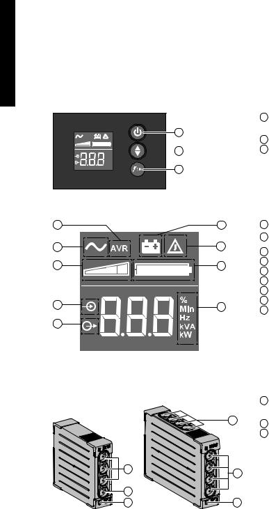
2. Description
AVR
%
Min
Hz kVA 

 kW
kW
6 ON/OFF button for the battery backup outlets
6 7 Scroll down
8 ASR LED
7
8
LCD
10 |
11 |
9 |
12 |
13 |
14 |
15 |
17 |
|
|
16 |
|
Outlets
650 / 850 1200 / 1600
9 UPS ON
10AVR mode
11Battery mode
12Internal fault
13Output load level
14Battery level
15Input measurements
16Output measurements
17Measuring unit
18Surge protection outlets
19Battery backup outlets
18 20 Protection (circuit breaker)
Out |
In |
Master |
l |
EcoContro |
19 |
19 |
|
|
18 |
|
20 |
20 |
6 |
614-06817-00 |

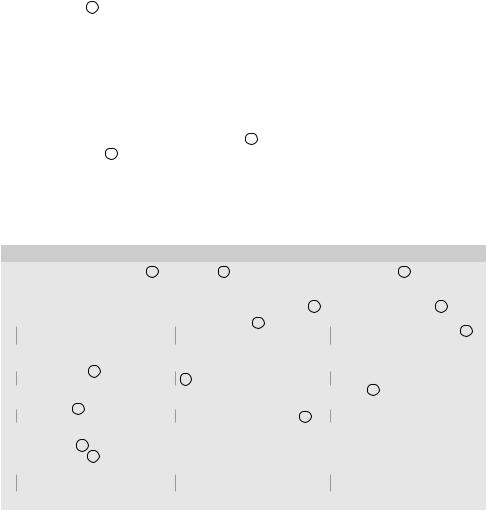
3. UPS connections |
English |
||
• |
Connect the UPS 1 to the AC-power system via a wall outlet with an earth connector, |
||
|
|||
|
using the supplied cord 4 for a UPS with FR/DIN sockets or with the supply cord of |
|
|
|
your computer for a UPS with IEC sockets (see figure A). |
|
|
• |
Plug critical equipment (computer, monitor, modem, etc.) into the outlets 19 providing |
|
|
|
battery backup power and surge protection (see figure B), taking care not to exceed |
|
|
|
the rated current indicated in amperes. |
|
|
• |
Other devices (printer, scanner, fax, etc.) can be connect to the surge protection outlets |
|
|
|
|||
|
18 (see figure B).The surge protection outlets are not backed up by battery power in |
|
|
|
the event of a power outage. |
|
|
Optional Internet modem / Network connection:
A modem or Ethernet data line can be protected against surges by connecting it via the UPS. Connect the existing device cable between the wall outlet and the UPS, and use a similar cable between the UPS and the device, as indicated in figure C (cable not supplied).
Optional USB connection:
The UPS device can be connected to the computer using the USB cable 5 supplied
(see figure C).
The software is available on the CD-ROM 5 or Eaton UPS Companion software is downloadable from powerquality.eaton.com.
Register for the warranty on powerquality.eaton.com.
4. Master and EcoControl outlets operating procedure
In order to limit energy consumption of peripherals (scanner, printer) in standby mode, the Ellipse PRO is equipped with EcoControl outlets that are dependent on the Master outlet. When the main device supplied by the Master outlet (computer) is shut down, the EcoControl outlets are automatically deactivated and the peripherals shut down.
This function (deactivated by default) is validated and configured using the configuration tool integrated in the software.
Note: when the function is activated, do not connect critical applications to EcoControl outlets.
Threshold setup
A default setup ensures the correct operation of the EcoControl function. However, depending on the consumption of the main load, the trigger threshold of the EcoControl function may have to be modified using the configuration software supplied with the
UPS:
•First, make sure that the function is activated in the "EcoControl Function" tab of the configuration tool.
•If the peripherals connected to the EcoControl outlets do not switch off when the main load is not in normal operation (ex: when in standby mode), the detection threshold value must be set to High.
•If the rated consumption level of the main load is low and the EcoControl outlets shut down when the main load is operating normally, the detection threshold value must be set to Low.
614-06817-00 |
7 |

English
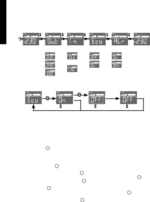
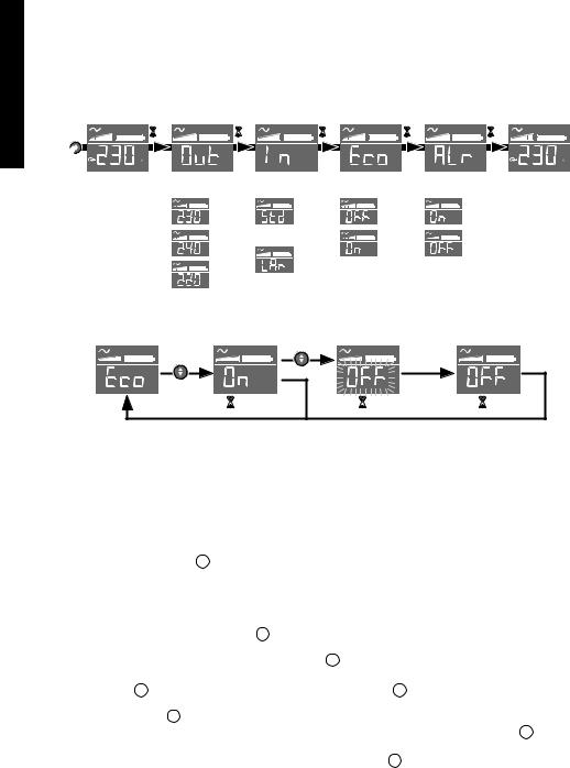
5. UPS setting through the LCD
Release scroll down button to select menu
5s |
2s |
2s |
2s |
2s |
|
Output voltage Input voltage |
EcoControl |
Alarm |
|
tolerance |
|
|
(165 - 264 V) |
(150 - 284 V)
Example of setting
10s |
5s |
5s |
|
Save the new value |
|
•LCD shut off if no activity for 3 minutes.
6.Operation
Battery charge
The UPS charges the battery as soon as it is connected to the AC outlet, whether button
6 is pressed or not.When used for the first time, the battery will only provide its maximum performance after it has been charged for 8 hours. It is recommended that the UPS be permanently connected to the AC power supply to ensure the best possible performance.
Switching-on the UPS
Press button 6 for about 1 second.
Surge protection outlets 18 without battery backup
Equipment connected to these outlets is supplied as soon as the AC cord 4 is plugged in.They are not affected by button 6 .
Battery backup outlets 19
Equipment connected to these outlets is supplied as soon as button 6 turns green
(see figure D).
These outlets can be turned on even if the UPS is not connected to AC power (button 6 flashes).
8 |
614-06817-00 |
|
|
AC-power disturbance |
|
|
|
|
|
|
|
|
• If AC power is disturbed or fails, the UPS continues to operate on battery power. |
|
English |
||||
|
|
Button 6 flashes green. In normal mode, the audible alarm beeps every ten seconds, |
|
|||||
|
|
|
|
|||||
|
|
then every three seconds when the end of battery backup time is near. In silent mode, |
|
|
||||
|
|
the audible alarm simply beeps once when the UPS transfers to battery power. |
|
|
||||
|
|
• If the power outage lasts longer than the battery backup time, the UPS shuts down |
|
|
||||
|
|
and automatically restarts when power is restored. Following a complete discharge, a |
|
|
||||
|
|
few hours are required to recharge the battery back to full backup time. |
|
|
||||
|
|
|
||||||
|
|
Surge protection: |
|
|
|
|
|
|
|
|
All outlets include surge protection. |
|
|
|
|
||
|
|
Shutdown of the battery backup outlets 19 |
|
|
|
|
||
|
|
Press button 6 for more than two seconds. |
|
|
|
|
||
7.Troubleshooting |
|
|
|
|
|
|
||
(For further information, visit the www.powerquality.eaton.com site or contact after-sales support.) |
|
|
||||||
|
|
|
|
|
|
|
|
|
|
|
Problem |
|
Diagnostic |
|
Solution |
|
|
|
|
|
|
|
|
|||
|
|
|
|
|
|
|
|
|
1 |
|
• The battery backup outlets 19 |
|
• Button 6 is not lighted on. |
|
• Press button 6 and check that |
|
|
|
|
|
|
|
||||
|
|
are not supplied with power. |
|
|
|
it turns green. |
|
|
|
|
|
|
|
|
|
||
2 |
|
• The connected devices are not |
|
• The devices are not connected |
|
• Connect the devices to the |
|
|
|
|
|
|
|
||||
|
|
supplied when AC power fails. |
|
to the battery backup outlets 19. |
|
battery backup outlets 19. |
|
|
|
|
|
|
|
|
|||
3 |
|
• AC power is available, but the |
|
• Circuit breaker 20, located at |
|
• Disconnect excess equipment |
|
|
|
|
|
|
|
||||
|
|
UPS operates on battery power. |
|
the rear of the UPS, has been |
|
and reset the circuit breaker 20 |
|
|
|
|
|
|
tripped by an overload on the |
|
by pressing the corresponding |
|
|
|
|
|
|
UPS output. |
|
button. |
|
|
|
|
|
|
|
|
|
||
4 |
|
• Green button 6 flashes and |
|
• The UPS battery backup outlets |
|
• Disconnect excess equipment |
|
|
|
|
|
|
|
||||
|
|
audible alarm beeps every 3 |
|
19 are overloaded. |
|
connected to the battery backup |
|
|
|
|
seconds. |
|
|
|
outlets 19 . |
|
|
5 |
|
• Fault sign 12 appear on the LCD |
|
• A fault has occurred on the UPS. |
|
• Call after-sales support. |
|
|
|
|
|
|
|
||||
|
|
panel and audible alarm beeps |
|
The battery backup outlets 19 are |
|
|
|
|
|
|
continuously. |
|
no longer supplied. |
|
|
|
|
6 |
|
• Green LED 8 is off and the |
|
• Surge protection is no longer |
|
• Call after-sales support. |
|
|
|
|
|
|
|
||||
|
|
filtered outlets 18 are supplied. |
|
provided. |
|
|
|
|
|
|
|
|
|
|
|
||
7 |
|
• EcoControl outlets keep powered |
|
• EcoControl function is not |
|
• Activate or set properly |
|
|
|
|
|
|
|
||||
|
|
when main application (Master |
|
activated or not properly set. |
|
EcoControl function using the |
|
|
|
|
outlet) is stopped. |
|
|
|
software provided with the |
|
|
|
|
|
|
|
|
product. |
|
|
|
|
|
|
|
|
|
|
|
614-06817-00 |
9 |

FRANÇAIS |
1. Conditions d'utilisation |
|
• |
Cet appareil est une Alimentation Sans Interruption (ASI) conçue pour alimenter un |
|
|
|
ordinateur et ses périphériques, des appareils deTV, HI-FI, Vidéo, à l’exclusion de tout |
|
|
autre appareil électrique (éclairage, chauffage, électroménager...). |
|
• |
L'ASI peut être installée en position horizontale, verticale, ou en Rack 2U (kit |
|
|
optionnel). |
2. Description
6
AVR
%
 7
7
Min
Hz kVA kW
8
LCD
10 |
11 |
9 |
12 |
13 |
14 |
15 |
17 |
|
|
16 |
|
Prises
650 / 850 1200 / 1600
18
Out |
In |
Master |
l |
EcoContro |
19 |
19 |
|
|
18 |
|
20 |
20 |
6Bouton MARCHE/ARRÊT pour les prises secourues par batteries
7Défilement
8Voyant ASR
9 ASI en fonctionnement
10Mode AVR
11Mode batterie
12Défaut interne
13Niveau de charge en sortie
14Niveau de batterie
15Mesures en entrée
16Mesures en sortie
17Unité de mesure
18Prises protégées contre les surtensions.
19Prises secourues par batterie
20Protection (disjoncteur)
10 |
614-06817-00 |
3. Raccordement de l'ASI |
FRANÇAIS |
||
• |
Raccorder l'ASI 1 au réseau électrique sur une prise murale avec terre, à l'aide du |
||
|
|||
|
cordon fourni 4 pour une ASI avec prises FR/DIN ou avec le cordon d'alimentation de |
|
|
|
votre ordinateur pour une ASI avec prises IEC (voir figure A). |
|
|
• |
Connecter les prises des appareils critiques (ordinateur, écran, modem...) sur les |
|
|
|
prises secourues par batterie 19 et protégées contre les surtensions (voir figure B), en |
|
|
|
ne dépassant pas le courant indiqué en Ampères. |
|
|
• |
Les autres appareils (imprimante, scanner, fax…) peuvent être branchés sur les prises |
|
|
|
|||
|
protégées contre les surtensions 18 (voir figure B); les prises protégées ne sont pas |
|
|
|
secourues en cas de coupure de courant. |
|
|
Liaison Modem Internet / Réseau facultative :
La ligne modem ou réseau Ethernet peut être protégée contre les surtensions en la raccordant via l'ASI. Pour celà, relier d'une part la prise murale à l'ASI avec le cordon de l'appareil à protéger, et d'autre part l'ASI à cet appareil à l'aide d'un cordon identique, comme indiqué figure C (cordon non fourni).
Liaison USB facultative :
L’appareil ASI peut être connecté à l’ordinateur via le câble USB 5 fourni (voir figure C). Le logiciel est disponible sur le CD-ROM 5 . Il est également possible de télécharger le logiciel Eaton UPS Companion depuis le site powerquality.eaton.com.
Enregistrement de la garantie sur le site powerquality.eaton.com.
4. Mode de fonctionnement des prises Master et EcoControl
Afin de limiter la consommation d’énergie des périphériques (scanner, imprimante) en mode veille, Ellipse PRO est muni de prises EcoControl dépendantes de la prise
Master (voir figure B). Quand l’application principale alimentée par la prise Master
(ordinateur) est arrêtée, les prises EcoControl sont automatiquement désactivées et les périphériques s’arrêtent.
La validation et le paramétrage de cette fonction (désactivée par défaut) se font par l’intermédiaire de l’outil de configuration intégré au logiciel.
Note: lorsque la fonction est activée, ne pas connecter d’applications critiques sur les prises EcoControl.
Paramétrage des seuils
Un paramétrage par défaut assure le bon fonctionnement de la fonction EcoControl. Cependant, selon le niveau de consommation de la charge principale, il peut être nécessaire de modifier le seuil de déclenchement de la fonction EcoControl en utilisant le logiciel de configuration livré avec l’onduleur :
•s’assurer tout d’abord que la fonction soit bien activée dans le volet "Fonction EcoControl" de l’outil de configuration.
•si les périphériques connectés sur les prises EcoControl ne s’arrêtent pas quand la charge principale n’est pas en fonctionnement normal (ex : pendant une mise en veille), il est nécessaire d’augmenter la valeur du seuil de détection au niveau Haut.
•si le niveau de consommation nominal de la charge principale est faible et que les prises EcoControl s’arrêtent alors que la charge principale fonctionne normalement, il est nécessaire d’abaisser la valeur du seuil de détection au niveau Bas.
614-06817-00 |
11 |
FRANÇAIS
5. Réglage de l'ASI à l'aide de l'afficheur LCD
Relâcher le bouton de défilement pour sélectionner le menu
5s |
2s |
2s |
2s |
2s |
|
Output voltage Input voltage |
EcoControl |
Alarm |
|
tolerance |
|
|
(165 - 264 V) |
(150 - 284 V)
Exemple de réglage
10s |
5s |
5s |
|
Enregistre la nouvelle valeur |
|
• L'afficheur LCD s'éteint après 3 minutes d'inactivité.
6. Utilisation
Charge batterie
L'ASI charge sa batterie dès qu’elle est connectée au réseau électrique quel que soit l'état du bouton 6 . A la première utilisation, la batterie ne donne sa pleine autonomie qu'après une recharge de 8 heures. Pour conserver la meilleure autonomie, il est conseillé de laisser l'ASI branchée en permanence sur le réseau électrique.
Mise en marche de l'ASI
Appuyer sur le bouton 6 environ 1 seconde.
Prises protégées contre les surtensions 18 non secourues
Les appareils raccordés sur ces prises sont alimentés dès que le câble d’entrée 4 est branché sur une prise murale. Le bouton 6 ne les commande pas.
Prises secourues 19
Les appareils raccordés sur ces prises sont alimentés dès que le bouton 6 est allumé en vert (voir figure D). Ces prises peuvent être mises en marche même si l'ASI n'est pas connectée au réseau électrique (bouton 6 clignotant).
12 |
614-06817-00 |
Perturbation du réseau électrique
•Si la tension de ce réseau est mauvaise ou absente, l'ASI continue à fonctionner sur batterie : le bouton 6 clignote en vert. En mode normal, l’alarme sonore émet un signal toutes les 10 secondes, puis toutes les 3 secondes lorsque la fin d'autonomie batterie approche. En mode silence, l'alarme sonore émet un bip au passage sur batterie.
•Si la durée de la coupure du réseau électrique dépasse l'autonomie batterie, l'ASI s'arrête puis redémarre automatiquement au retour du réseau électrique. Après décharge complète, quelques heures sont nécessaires pour restaurer l'autonomie complète.
Protection contre les surtensions :
Toutes les prises sont protégées contre les surtensions.
Arrêt des prises secourues 19
Appuyer plus de 2 secondes sur le bouton 6 .
7. Dépannage
(Pour toutes informations, consulter le site www.powerquality.eaton.com ou notre Service
Après-Vente)
|
|
Symptôme |
|
Diagnostic |
|
Remède |
|
|
|
|
|||
1 |
|
• Les prises secourues 19 ne sont |
|
• Le bouton 6 n’est pas allumé. |
|
• Appuyer sur le bouton 6 et |
|
|
|
||||
|
|
pas alimentées. |
|
|
|
vérifier qu’il s'est allumé en vert. |
|
|
|
|
|
||
2 |
|
• Les appareils raccordés ne sont |
|
• Les appareils ne sont pas |
|
• Raccorder ces appareils sur les |
|
|
plus alimentés lors d'une coupure |
|
raccordés sur les prises secourues prises secourues 19. |
||
|
|
du réseau électrique. |
|
19. |
|
|
|
|
|
|
|
||
3 |
|
• Le réseau électrique est présent |
|
• Le disjoncteur 20, placé à |
|
• Débrancher l’appareil en cause |
|
|
|
||||
|
|
mais l'ASI fonctionne sur sa |
|
l'arrière de l'ASI, a été déclenché |
|
en sortie et réarmer le disjoncteur |
|
|
batterie. |
|
par une surcharge sur la sortie de |
|
20 en appuyant sur son bouton. |
|
|
|
|
l'ASI. |
|
|
|
|
|
|
|
|
|
4 |
|
• Le bouton vert 6 clignote et |
|
• L'ASI subit une surcharge sur les |
|
• Débrancher l’appareil en cause |
|
|
une alarme sonore émet un signal |
|
prises secourues 19. |
|
des prises secourues 19. |
|
|
toutes les 3 secondes. |
|
|
|
|
5 |
|
• Le signal de défaut 12 apparaît |
|
• L'ASI a subit un défaut. Les |
|
• Faire appel au service après |
|
|
|
||||
|
|
sur l'écran LCD et l'alarme sonore |
|
prises secourues 19 ne sont plus |
|
vente. |
|
|
émet un signal continu. |
|
alimentées. |
|
|
6 |
|
• Le voyant vert 8 est éteint et les |
|
• La protection contre les |
|
• Faire appel au service après |
|
|
|
||||
|
|
prises 18 sont alimentées. |
|
surtensions n'est plus assurée. |
|
vente. |
|
|
|
|
|||
7 |
|
• Les prises EcoControl restent |
|
• La fonction EcoControl n'est pas |
|
• Activer ou paramétrer |
|
|
|
||||
|
|
alimentées alors que l'application |
|
activée ou est mal paramétrée. |
|
correctement la fonction |
|
|
principale (prise Master) est |
|
|
|
EcoControl en utilisant le logiciel |
|
|
arrêtée. |
|
|
|
fourni avec le produit. |
|
|
|
|
|
||
FRANÇAIS
614-06817-00 |
13 |

DEUTSCH |
1.Allgemeine Betriebsbedingungen |
||
• |
Bei dem Gerät handelt es sich um eine Unterbrechungsfreie Stromversorgungsanlage |
||
|
|||
|
|
(USV) für die sichere Energieversorgung eines Computers und der zugehörigen |
|
|
|
Peripheriegeräte, Fernsehgeräte, HiFi-Anlagen, Videorecorder... Das Gerät dient |
|
|
|
nicht zum Anschluß sonstiger elektrischer Verbraucher (Leuchtkörper, Heizgeräte, |
|
|
|
Elektrohaushaltsgeräte...). |
|
|
• |
Die USV kann horizontal, vertikal, oder im 2U-Rack (optionaler Bausatz) installiert |
|
|
|
werden. |
|
|
|
||
2. Beschreibung
AVR
%
Min
Hz kVA 

 kW
kW
6 EIN/AUSTASTE für die Notstrombatterie-Anschlüsse
6 |
7 |
Scroll-Knopf |
|
||
7 |
8 |
ASR LED |
|
|
8
LCD
10 |
11 |
9 |
12 |
13 |
14 |
15 |
17 |
|
|
16 |
|
Anschlussbuchsen
650 / 850 1200 / 1600
18
Out |
In |
Master |
l |
EcoContro |
19 |
19 |
|
|
18 |
|
20 |
20 |
9 USV EIN
10AVR-Modus
11Batteriemodus
12Interner Fehler
13Ausgangs-Lastanzeige
14Batterieladestand
15Eingangsmessungen
16Ausgangsmessungen
17Messeinheit
18ÜberspannungsgeschützteBuchsen
19Batteriegepufferte Buchsen
20Schutz (Trennschalter)
14 |
614-06817-00 |

3. Anschluß der USV |
DEUTSCH |
|
• Die USV 1 mit Hilfe des Kabels 4 (bei einer USV mit FR/DIN-Anschlüssen) oder mit |
||
|
||
dem Anschlusskabel Ihres Computers (bei einer USV mit IEC-Anschlüssen) mittels |
|
|
einer Wandsteckdose an das Stromnetz anschließen. (siehe Abbildung A). |
|
|
• Die vor Netzausfall und Überspannung zu schützendenVerbraucher (Computer, |
|
|
Monitor, Modem...) an die Batteriegepuffertern Ausgangssteckdosen 19 der USV |
|
|
anschließen (siehe Abb. B). Der angegebene Nennstrom (in A) darf nicht überschritten |
|
|
werden. |
|
|
|
||
• Andere Geräte (Drucker, Scanner, Fax usw.) können an den |
|
|
überspannungsgeschützten Buchsen 18 angeschlossen werden (siehe Abbildung B). |
|
|
Die überspannungsgeschützten Buchsen werden im Falle eines Stromausfalls nicht |
|
|
von der Batterie versorgt. |
|
|
Schutz derTelefonund Datenleitung (optional): |
|
|
Die ggf. verwendeteTelefonoder Datenleitung kann ebenfalls gegen Überspannungen |
|
|
geschützt werden. Hierzu ist das bereits vorhandene Datenkabel derTelefonbzw. |
|
|
Datensteckdose mit der USV zu verbinden. Desweiteren ist ein Anschluß der USV an den |
|
|
Rechner vorzunehmen. (siehe Abb. C). |
|
|
Optionale USB-Schnittstelle: |
|
|
Die USV kann über das USB-Kabel 5 (im Lieferumfang enthalten) an den Computer |
|
|
angeschlossen werden (siehe Abbildung C). |
|
|
Die Software findet sich auf der CD-ROM 5 . Die Software Eaton UPS Companion auch |
|
|
unter powerquality.eaton.com heruntergeladen werden. |
|
|
Registrieren Sie unter powerquality.eaton.com gleichzeitig Ihre Garantie. |
|
|
4. Funktionsweise der Master-und EcoControl-Steckdosen |
|
|
Um den Energieverbrauch der Periphergeräte (Scanner, Drucker) im Standby-Modus zu |
|
|
reduzieren, ist die Ellipse PRO mit von der Master-Steckdose abhängigen EcoControl- |
|
|
Steckdosen ausgerüstet (siehe Abbildung B). Wenn die von der Master-Steckdose |
|
|
versorgte Hauptanwendung (Computer) ausgeschaltet ist, werden die EcoControl- |
|
|
Steckdosen automatisch deaktiviert und die Peripheriegeräte abgeschaltet. |
|
|
Die Aktivierung und Parametrierung dieser Funktion (standardmäßig deaktiviert) erfolgt |
|
|
mithilfe des in der Software. |
|
Anmerkung: Schließen Sie keine kritischen Anwendungen an die EcoControl-Steckdose an, wenn diese Funktion aktiviert ist.
Parametrierung der Grenzwerte
Durch die standardmäßige Parametrierung ist gewährleistet, dass die EcoControl- Funktion ordnungsgemäß funktioniert.
Entsprechend dem jeweiligen Verbrauch der Hauptlast kann es jedoch erforderlich sein, die Auslöseschwelle der EcoControl-Funktion mithilfe der im Lieferumfang der USV enthaltenen Konfigurations-Software zu ändern:
•Vergewissern Sie sich zunächst, dass diese Funktion im Fenster "EcoControl function" es Konfigurationstools aktiviert ist.
•Falls sich die an die EcoControl-Steckdosen angeschlossenen Peripheriegeräte nicht automatisch abschalten, wenn die Hauptlast sich nicht im Normalbetrieb befindet (z.B. im Standby-Betrieb), muss die Auslöseschwelle auf den Wert High eingestellt werden.
•Wenn die Hauptlast einen geringen Nennverbrauch hat und die EcoControl- Steckdosen abschalten, obwohl die Hauptlast im Normalbetrieb läuft, muss die
Auslöseschwelle auf Low gestellt werden.
614-06817-00 |
15 |

DEUTSCH
5. Einstellung der USV über die LCD
Rasten Sie den Scroll-Knopf aus, um das Menü zu wählen
5s |
2s |
2s |
2s |
2s |
|
Output voltage Input voltage |
EcoControl |
Alarm |
|
tolerance |
|
|
(165 - 264 V) |
(150 - 284 V)
Beispiel für eine Einstellung
10s |
5s |
5s |
|
Speichern Sie den neuen Wert |
|
•Das LCD schaltet nach 3 Minuten ohne Betätigung ab.
6.Aufbau und Funktionsumfang
Aufladen der Batterie
Sobald die USV an das Netz angeschlossen ist, wird die Batterie unabhängig von der Schaltstellung desTasters 6 aufgeladen. Beim ersten Gebrauch steht die volle
Autonomiezeit erst nach einer Aufladezeit der Batterie von 8 Stunden zurVerfügung. Um die optimale Batterieleistung zu gewährleisten, ist es ratsam, die USV ständig an das Stromnetz angeschlossen zu lassen.
Einschalten der USV
DieTaste 6 mehr als 1 Sekunde drücken.
Überspannungsgeschützte Buchsen 18 ohne Batteriepufferung
Die Stromversorgung der an diese Steckdosen angeschlossenen Verbraucher erfolgt, sobald das Netzkabel 4 mit einer Netzsteckdose verbunden wird. Der Drucktaster 6 hat keinen Einfluß auf diese Steckdosen.
Steckdosen mit Batteriepufferung 19
Die Stromversorgung der an diese Steckdosen angeschlossenen Verbraucher erfolgt, sobald die LED desTasters 6 grün leuchtet (siehe Abbildung D). Die Steckdosen können auch ohne Netzspannung eingeschaltet werden (Taster-LED 6 blinkt).
16 |
614-06817-00 |

|
|
Ausfall oder Störung der Netzspannung |
|
|
|
DEUTSCH |
||
|
|
• Bei Ausfall oder Störung der Netzspannung arbeitet die USV im Batteriebetrieb weiter |
||||||
|
|
|
||||||
|
|
(Taster-LED 6 blinkt grün). Im Batteriebetrieb ertönt alle 10 Sekunden ein Warnsignal |
|
|||||
|
|
(Summer). Kurz vor Ablauf der Batterieautonomiezeit verkürzt sich dasTonintervall auf |
|
|||||
|
|
3 Sekunden. Im Silent-Modus ertönt der Summer nur einmalig bei Umschaltung auf |
|
|||||
|
|
Batteriebetrieb. |
|
|
|
|
|
|
|
|
• Ist die Dauer des Netzausfalls länger als die verfügbare Autonomiezeit, schaltet |
|
|||||
|
|
die USV ab und startet bei Netzrückkehr wieder automatisch. Nach vollständiger |
|
|||||
|
|
|||||||
|
|
Entladung sind einige Stunden erforderlich, bis die volle Autonomiezeit erneut zur |
|
|||||
|
|
Verfügung steht. |
|
|
|
|
|
|
|
|
Überspannungsschutz: |
|
|
|
|
|
|
|
|
Alle Steckdosen sind Überspannungsschutz. |
|
|
|
|
||
|
|
Abschaltung der gepufferten Steckdosen 19 |
|
|
|
|
||
|
|
Zur Abschaltung der SteckdosenTaster 6 2 Sekunden lang drücken. |
|
|||||
7. Fehlerbehebung |
|
|
|
|
|
|
||
(Weitere Informationen unter www.powerquality.eaton.com oder bei Ihrem Eaton- |
|
|||||||
Kundendienst) |
|
|
|
|
|
|
||
|
|
Fehler |
|
Fehlerursache |
|
Fehlerbehebung |
|
|
|
|
|
|
|
||||
1 |
|
• Keine Spannung an den |
|
• Taster 6 leuchtet nicht. |
|
• Taster 6 betätigen; grüne |
|
|
|
|
|
|
|||||
|
|
gepufferten Steckdosen 19. |
|
|
|
Kontroll-LED muß leuchten. |
|
|
|
|
|
|
|
|
|||
2 |
|
• Keine Stromversorgung der |
|
• Geräte sind nicht an die |
|
• Betreffende Geräte an die |
|
|
|
|
angeschlossenen Geräte bei |
|
gesicherten Steckdosen 19 |
|
gesicherten Steckdosen 19 |
|
|
|
|
Netzausfall. |
|
angeschlossen. |
|
anschließen. |
|
|
3 |
|
• Trotz vorhandener |
|
• DerTrennschalter 20 auf der |
|
• Betreffenden Verbraucher |
|
|
|
|
|
|
|||||
|
|
Netzspannung arbeitet die USV im |
|
Rückseite der USV, wurde von |
|
entfernen und Schutzschalter |
|
|
|
|
Batteriebetrieb. |
|
einer Überlast am USV-Ausgang |
|
20 durch Betätigung wieder |
|
|
|
|
|
|
ausgelöst. |
|
zurückstellen. |
|
|
|
|
|
|
|
|
|||
4 |
|
• Die grüneTaste 6 blinkt und |
|
• Überlast an den gepufferten |
|
• Betreffenden Verbraucher von |
|
|
|
|
|
|
|||||
|
|
alle 3 Sekunden ertönt ein Alarm- |
|
Steckdosen 19. |
|
den gesicherten Steckdosen 19 |
|
|
|
|
Piepston. |
|
|
|
trennen. |
|
|
5 |
|
• Das Fehlersymbol 12 erscheint |
|
• USV-Störung - gepufferte |
|
• Kundendienst benachrichtigen. |
|
|
|
|
|
|
|||||
|
|
auf der LCD-Anzeige, begleitet von |
|
Steckdosen. 19 werden nicht |
|
|
|
|
|
|
einem ununterbrochenen Alarm- |
|
mehr versorgt. |
|
|
|
|
|
|
Piepston. |
|
|
|
|
|
|
|
|
|
|
|
|
|
|
|
6 |
|
• Grüne LED 8 ist erloschen und |
|
• Überspannungsschutz ist nicht |
|
• Kundendienst benachrichtigen. |
|
|
|
|
|
|
|||||
|
|
die Steckdosen 18 liefern |
|
mehr gewährleistet. |
|
|
|
|
|
|
Spannung. |
|
|
|
|
|
|
|
|
|
|
|
|
|
|
|
7 |
|
• Die EcoControl-Steckdosen |
|
• EcoControl-Funktion ist nicht |
|
• EcoControl-Funktion mit Hilfe |
|
|
|
|
|
|
|||||
|
|
bleiben trotz Abschaltung der |
|
aktiviert oder nicht korrekt |
|
der beigestellten Software |
|
|
|
|
Hauptlast (Master-Steckdose) auch |
|
parametriert. |
|
aktivieren oder korrekt |
|
|
|
|
weiterhin unter Spannung. |
|
|
|
parametrieren. |
|
|
|
|
|
|
|
|
|||
614-06817-00 |
17 |

italiano
1. Condizioni di utilizzo
• Questo apparecchio è un sistema statico di continuità (UPS) progettato per alimentare un computer e le relative periferiche, apparecchiTV, Hi-Fi, videoregistratori, ad eccezione di qualsiasi altro apparecchio elettrico (impianto d’illuminazione, riscaldamento, elettrodomestici, ecc.).
• L'UPS può essere installato in posizione orizzontale, verticale o in Rack 2U (kit in opzione).
2. Descrizione
|
|
6 |
Pulsante ON/OFF per le |
|
|
|
prese di alimentazione di |
AVR |
6 |
|
riserva da batteria |
|
7 Scorrimento verso il basso |
||
|
|
||
% |
7 |
8 |
LED ASR |
Min |
|
|
|
Hz |
|
|
|
kVA |
|
kW |
8 |
|
LCD
10 |
11 |
9 |
UPS acceso |
|
|
10 |
Modalità AVR |
9 |
12 |
11 |
Modalità batteria |
|
|
12 |
Guasto interno |
13 |
14 |
13 |
Livello carico uscita |
|
|
14 |
Livello batteria |
|
|
15 |
Misurazioni ingresso |
|
|
16 |
Misurazioni uscita |
15 |
17 |
17 |
Unità di misurazione |
|
|
|
|
16 |
|
|
|
Prese
650 / 850 |
1200 / 1600 |
|
18 |
Prese di protezione contro le |
|
|
|
|
sovratensioni |
|
|
18 |
19 |
Prese di alimentazione di |
|
|
|
riserva da batteria |
|
|
|
|
20 |
Protezione (interruttore di |
|
|
|
|
corrente) |
Out |
In |
Master |
l |
EcoContro |
19 |
19 |
|
|
18 |
|
20 |
20 |
18 |
614-06817-00 |

3. Collegamento dell’UPS |
italiano |
||
• |
Collegare l’UPS 1 alla rete elettrica su una presa murale dotata di messa a terra, |
||
|
|||
|
servendosi del cavo 4 fornito in dotazione per un UPS con prese FR/DIN o del cavo di |
|
|
|
alimentazione del computer per un UPS con prese IEC (vedere figura A). |
|
|
• |
Collegare le prese degli apparecchi critici (computer, schermo, modem) sulle |
|
|
|
prese con alimentazione di soccorso fornita dalla batteria 19 e protette contro le |
|
|
|
sovratensioni (vedere figura B), senza superare la corrente indicata in ampere. |
|
|
• |
Altri dispositivi (stampante, scanner, fax, ecc.) possono essere collegati alle prese |
|
|
|
|||
|
di protezione contro le sovratensioni 18 (vedere figura B). Le prese di protezione |
|
|
|
contro le sovratensioni non ricevono alimentazione di riserva dalla batteria in caso di |
|
|
|
interruzione di corrente. |
|
|
Collegamento facoltativo Modem Internet / Rete Ethernet:
La linea modem o la rete Ethernet possono essere protette contro le sovratensioni tramite l’UPS. A tal fine, collegare la presa al telefonica sul muro all’UPS utilizzando il cavo dell’apparecchio da proteggere e poi collegare l’UPS a questo apparecchio con un cavo indentico, come indicato nella figura C (cavo non fornito).
Collegamento USB facoltativo:
Il dispositivo UPS può essere collegato al computer utilizzando il cavo USB 5 fornito
(vedere figura C).
Il software è disponibile sul CD-ROM 5 oppure il software Eaton UPS Companion può essere scaricato da powerquality.eaton.com.
Registratevi ai fini della garanzia sul sito powerquality.eaton.com.
4. Modalità di funzionamento delle prese Master e EcoControl
Per limitare i consumi energetici delle periferiche (scanner, stampante) in modalità stand-by, la Ellipse PRO è dotata di prese EcoControl dipendenti dalla presa Master (vedi figura B). Quando l’applicazione principale alimentata dalla presa Master (computer) è disattivata, anche le prese EcoControl sono disattivate automaticamente e le periferiche si spengono.
La conferma e l’impostazione di questa funzione (disattivata per default) avvengono tramite il tool di configurazione integrato al software.
N.B.: quando la funzione è attivata, non collegare applicazioni critiche alle prese EcoControl.
Impostazione dei parametri delle soglie
L’impostazione per default garantisce il corretto funzionamento della funzione
EcoControl.
Tuttavia, secondo il livello di consumo della carica principale, può essere necessario modificare la soglia di attivazione della funzione EcoControl utilizzando il software di configurazione fornito con l’inverter:
•Accertarsi innanzitutto che la funzione sia correttamene attivata nella scheda "EcoControl function" del tool di configurazione.
•Qualora le periferiche collegate alle prese EcoControl non si spengano quando la carica principale non è in modalità di funzionamento normale (es. durante la modalità in stand-by), è necessario incrementare il valore della soglia di rilevamento al livello
High.
•Se invece il livello di consumo nominale della carica principale è basso e le prese EcoControl si disattivano quando la carica principale funziona normalmente, è necessario diminuire il valore della soglia di rilevamento al livello Low.
614-06817-00 |
19 |
italiano
5. Impostazione dell'UPS attraverso il pannello LCD
Rilasciare il pulsante di scorrimento verso il basso per selezionare i menu
5s |
2s |
2s |
2s |
2s |
|
Output voltage Input voltage |
EcoControl |
Alarm |
|
tolerance |
|
|
(165 - 264 V) |
(150 - 284 V)
Esempio di impostazione
10s |
5s |
5s |
|
Salvare il nuovo valore |
|
• L'LCD si spegne in assenza di attività per 3 minuti.
6. Uso
Carica della batteria
l’UPS carica la batteria non appena viene collegato alla rete elettrica, indipendentemente dallo stato del tasto 6 . Al momento del primo utilizzo, la batteria fornisce un’autonomia completa solo dopo 8 ore di ricarica. Per mantenere un livello ottimale d’autonomia, si consiglia di lasciare sempre l’UPS collegato alla rete elettrica.
Accensione dell’UPS
Premere per 1 secondo il tasto 6 .
Prese di protezione contro le sovratensioni 18 senza alimentazione di riserva da batteria
Gli apparecchi collegati a queste prese vengono alimentati non appena il cavo di ingresso 4 viene collegato a una presa murale. Il tasto 6 non le comanda.
Prese assistite 19
gli apparecchi collegati a queste prese vengono alimentati non appena il tasto 6 si accende in verde (vedere figura D). Queste prese possono essere messe in funzione anche se l’UPS non e collegato alla rete elettrica (tasto 6 lampeggiante).
20 |
614-06817-00 |
Perturbazione della rete elettrica
•Se la tensione di questa rete è cattiva o assente, l’UPS continua a funzionare su batteria. Il tasto 6 lampeggia (spia verde). In modalità normale, l’allarme acustico emette un segnale ogni 10 secondi e poi ogni 3 secondi al momento in cui la fine dell’autonomia della batteria è prossima. In modalità silenziosa, l’allarme acustico emette un bip quando si passa su batteria.
•Se la durata dell’interruzione della corrente elettrica supera l’autonomia della batteria, l’UPS si arresta e poi si riavvia automaticamente al momento del ritorno della corrente elettrica. Dopo una scarica completa, sono necessarie alcune ore per ripristinare un’autonomia completa della batteria.
Protezione contro le sovratensioni:
Tutte le prese includono una protezione contro le sovratensioni.
Arresto delle prese assistite 19
Premere per più di 2 secondi il tasto 6 .
7.Interventi di riparazione
italiano
(Per ulteriori informazioni, consultare il sito www.powerquality.eaton.com o rivolgersi al nostro Servizio Assistenza)
|
|
Sintomo |
|
Diagnosi |
|
Rimedio |
|
|
|
|
|||
|
|
|
|
|
|
|
1 |
|
• Le prese assistite 19 non sono |
|
• Il tasto 6 non è acceso. |
|
• Premere il tasto 6 e verificare |
|
|
|
||||
|
|
alimentate. |
|
|
|
che sia acceso (spia verde). |
|
|
|
|
|
||
2 |
|
• Durante l’interruzione della |
|
• Gli apparecchi non sono |
|
• Collegare questi apparecchi |
|
|
corrente, gli apparecchi collegati |
|
collegati sulle prese assistite 19. |
|
sulle prese assistite 19. |
|
|
non sono più alimentati. |
|
|
|
|
3 |
|
• La corrente elettrica è presente, |
|
• L'interruttore di corrente |
|
• Disinserire l’apparecchio in |
|
|
|
||||
|
|
ma l’UPS funziona su batteria. |
|
20, situato sul retro dell'UPS, |
|
questione dall’uscita e riarmare |
|
|
|
|
è scattato a causa di un |
|
l’interruttore 20 premendo il |
|
|
|
|
sovraccarico sull'uscita dell'UPS. |
|
tasto relativo. |
|
|
|
|
|
||
4 |
|
• Il pulsante verde 6 lampeggia e |
|
• L’UPS subisce un sovraccarico |
|
• Disinserire l’apparecchio in |
|
|
un allarme acustico risuona ogni |
|
sulle prese assistite 19. |
|
questione dalle prese assistite |
|
|
3 secondi. |
|
|
|
19. |
|
|
|
|
|
||
5 |
|
• Un simbolo di guasto 12 |
|
• L’UPS ha subito un guasto. Le |
|
• Rivolgersi al Servizio Assistenza. |
|
|
|
||||
|
|
appare sul pannello LCD e un |
|
prese assistite 19 non sono più |
|
|
|
|
allarme acustico risuona in modo |
|
alimentate. |
|
|
|
|
continuo. |
|
|
|
|
|
|
|
|
|
|
|
6 |
|
• La spia verde 8 è spenta e le |
|
• La protezione contro le |
|
• Rivolgersi al Servizio Assistenza. |
|
|
|
||||
|
|
prese 18 sono alimentate. |
|
sovratensioni non è più garantita. |
|
|
|
|
|
|
|
||
7 |
|
• Le prese EcoControl restano |
|
• La funzione EcoControl non |
|
• Attivare e impostare |
|
|
|
||||
|
|
alimentate quando l'applicazione |
|
è attivata o non è impostata |
|
correttamente la funzione |
|
|
principale (presa Master) viene |
|
correttamente. |
|
EcoControl utilizzando il software |
|
|
arrestata. |
|
|
|
fornito insieme al prodotto. |
|
|
|
|
|
614-06817-00 |
21 |
Español |
1. Condiciones de uso |
|
• |
Este aparato es un Sistema de Alimentación Ininterrumpida (SAI) diseñado para |
|
|
|
alimentar principalmente un ordenador y sus periféricos exceptuando, aparatos deTV, |
|
|
HI-FI,Vídeo, excepto cualquier otro tipo de aparato eléctrico (alumbrado, calefacción, |
|
|
electrodomésticos, etc.). |
|
• |
El SAI puede instalarse en posición horizontal, vertical, o en Rack 2U (kit opcional). |
2. Descripción
6
AVR
%
 7
7
Min
Hz kVA kW
8
LCD
10 |
11 |
9 |
12 |
13 |
14 |
15 |
17 |
|
|
16 |
|
Tomas
650 / 850 1200 / 1600
18
Out |
In |
Master |
l |
EcoContro |
19 |
19 |
|
|
18 |
|
20 |
20 |
6Botón de ENCENDIDO/
APAGADO para las tomas de la batería auxiliar
7Desplazamiento hacia abajo
8LED ASR
9 SAI conectado
10Modo AVR (regulación automática de voltaje)
11Modo de batería
12Fallo interno
13Nivel de carga de salida
14Nivel de la batería
15Mediciones de entrada
16Mediciones de salida
17Unidad de medición
18Tomas de corriente de protección contra sobretensiones
19Tomas de la batería auxiliar
20Protección (disyuntor)
22 |
614-06817-00 |

3.Conexiones del SAI
•Conectar el SAI 1 a la red eléctrica en una toma mural con tierra por medio del cable
4 suministrado con el SAI con tomas FR/DIN o con el cable de alimentación de su ordenador para un SAI con tomas IEC (véase la figura A).
•Conectar los enchufes de los aparatos críticos (ordenador, pantalla, módem, etc.) en las tomas alimentadas por la batería 19 y protegidas contra las sobretensiones (véase la figura B), no sobrepasando la corriente indicada en amperios.
•También pueden conectarse otros dispositivos (impresora, escáner, fax, etc.) a las tomas de corriente de protección contra sobretensiones 18 (véase la figura B). Las tomas de corriente de protección contra sobretensiones no pueden ser respaldadas con la alimentación de la batería en el caso de corte de corriente.
Protección de la linea de datos fax/módem/red ethernet (opcional):
La línea telefónica, fax, módem, red ethernet, podrá ser protegida contra las sobretensiones conectándose a través del SAI. Para ello conectar la toma mural al SAI con el cable del equipo a proteger, y por otra parte con un cable idéntico unir el SAI al equipo protegido, como se indica en el dibujo C (cable no suministrado).
Communicación USB / Serie (opcional):
El dispositivo SAI puede conectarse al ordenador mediante el cable USB 5 incluido
(véase la figura C).
El software está disponible en el CD-ROM 5 o también se puede descargar el software
de Eaton UPS Companion en powerquality.eaton.com.
Regístrese para disfrutar de la garantía en powerquality.eaton.com.
4. Instrucciones de funcionamiento de las tomas Master y EcoControl
Para reducir el consumo de energía de los periféricos (scanner, impresora) en modo de espera, Ellipse PRO cuenta con tomas EcoControl dependientes de la toma Master
(véase figura B). Cuando la aplicación principal alimentada por la toma Master (ordenador) se para, las tomas EcoControl se desactivan automáticamente y los periféricos se paran.
La validación y configuración de esta función (desactivada por defecto) se realiza mediante la herramienta de configuración integrada en el software.
Nota: Cuando la función esté activada, no conecte aplicaciones críticas a las tomas EcoControl.
Configuración de los umbrales
La configuración por defecto asegura el correcto funcionamiento de la función
EcoContol.
Sin embargo, según el nivel de consumo de la carga principal, puede que sea necesario modificar el umbral de activación de la función EcoControl mediante el programa de configuración proporcionado con el ondulador:
•Asegúrese primero de que la función está activada correctamente en la opción "EcoControl function" de la herramienta de configuración.
•Si los periféricos conectados a las tomas EcoControl no se paran cuando la carga principal no está en funcionamiento normal (p. ej., durante el modo de espera), es necesario aumentar el valor del umbral de detección al nivel High.
•Si el nivel de consumo nominal de la carga principal es bajo y las tomas EcoControl se paran cuando la carga principal funciona correctamente, es necesario disminuir el valor del umbral de detección al nivel Low.
Español
614-06817-00 |
23 |

Español
5. Ajuste del SAI en la pantalla LCD
Suelte el botón de desplazamiento para seleccionar el menú
5s |
2s |
2s |
2s |
2s |
|
Output voltage Input voltage |
EcoControl |
Alarm |
|
tolerance |
|
|
(165 - 264 V) |
(150 - 284 V)
Ejemplo de ajuste
10s |
5s |
5s |
|
Guarde el nuevo valor |
|
• La pantalla LCD se apagará si no registra actividad en un intervalo de tres minutos.
6. Utilización
Carga de la batería
El SAI carga su batería en el momento en que se conecta a la red eléctrica sin importar el estado del interruptor 6 . Al utilizar por primera vez, la batería proporciona su total autonomía sólo después de una recarga de 8 horas. Para mantener la mayor autonomía, se aconseja dejar el SAI conectado permanentemente a la red eléctrica.
Puesta en marcha del SAI
Pulsar el interruptor 6 1 segundo.
Tomas de corriente de protección contra sobretensiones 18 sin batería auxiliar
Los aparatos conectados a estas tomas son alimentados a partir del momento en que el cable de entrada 4 se conecta a una toma mural. No se pueden desconectar mediante el interruptor 6 .
Tomas auxiliadas 19
Los aparatos conectados a estas tomas son alimentados a partir del momento en que el interruptor 6 está encendido en verde (ver el dibujo D). Estas tomas se pueden poner en funcionamiento aún cuando el SAI no está conectado a la red eléctrica
(interruptor 6 parpadeando).
24 |
614-06817-00 |
 Loading...