


 Loading...
Eaton RT-8908LL, RTO-11707LL, RTO-11708LL, RTOF-11707LL, RTOF-11708LL Service Manual
...Service Manual
Fuller Heavy-Duty Transmissions
TRSM1500 EN-US
May 2017
RT-8908LL RTO-11707LL RTO-11708LL RTOF-11707LL RTOF-11708LL RTOF-14708LL RTX-11708LL RTX-14708LL RTXF-11708LL RTXF-14708LL RTO-11707DLL RTO-11709MLL RTO-11908LL RTO-11909ALL RTO-11909MLL RTO-13707DLL RTO-13707MLL RTO-14709MLL
RTO-14908LL RTO-14909ALL RTO-14909MLL RTO-16908LL RTO-16909ALL RTOF-11709MLL RTOF-11908LL RTOF-11909ALL RTOF-11909MLL RTOF-13707DLL RTOF-13707MLL RTOF-14709MLL RTOF-14908LL RTOF-14909ALL RTOF-14909MLL RTOF-16908LL RTOF-16909ALL RTX-11715
RTX-14715 RTXF-11715 RTXF-14715 RTXF-15715
Warnings and Precautions
Warnings and Precautions
! WARNING
Before starting a vehicle always be seated in the driver’s seat, place the transmission in neutral, set the parking brakes and disengage the clutch.
Before working on a vehicle place the transmission in neutral, set the parking brakes and block the wheels.
Before towing the vehicle place the transmission in neutral, and lift the rear wheels off the ground, remove the axle shafts, or disconnect the driveline to avoid damage to the transmission during towing.
The description and specifications contained in this service publication are current at the time of printing.
Eaton Corporation reserves the right to discontinue or modify its models and/or procedures and to change specifications at any time without notice.
Any reference to brand name in this publication is made as an example of the types of tools and materials recommended for use and should not be considered an endorsement. Equivalents may be used.
This symbol is used throughout this manual to call attention to procedures where carelessness or failure to follow specific instructions may result in personal injury and/or component damage.
Departure from the instructions, choice of tools, materials and recommended parts mentioned in this publication may jeopardize the personal safety of the service technican or vehicle operator.
Warning: Failure to follow indicated procedures creates a high risk of personal injury to the service technician.
Caution: Failure to follow indicated procedures may cause component damage or malfunction.
Note: Additional service information not covered in the service procedures.
Tip: Helpful removal and installation procedures to aid in the service of this unit.
Always use genuine Eaton replacement parts.
<![endif]>Procedure Service
i

Introduction
Transmission Overview
Air System:
Roadranger® Valve
Shift Bar Housing:
Levers/Housings
& Isolators
|
|
|
|
|
Auxiliary Section: |
||
|
|
|
|
|
Combination Cylinder |
||
|
|
|
|
|
|
Air System: |
|
|
|
|
|
|
|
Air Filter/Regulator |
|
Shift Bar Housing: |
|
|
|
||||
Shift Bar Housing Assembly |
Auxiliary Section: |
||||||
|
|
|
|
|
|||
|
Front Section: |
Auxiliary Countershaft |
|||||
|
|
|
|
||||
|
Reverse Idler |
Auxiliary Section: |
|||||
|
|
|
|
|
|||
|
|
|
|
|
Auxiliary Case Assy |
||
|
|
|
|
|
|
Auxiliary Section: |
|
|
|
|
|
|
|
Mainshaft & Synchro |
|
Front Section: |
|
|
|
Auxiliary Section: |
|||
|
|
||||||
Clutch Housing / Case Assembly |
|
|
|
||||
|
|||||||
|
|
|
|
|
|
Auxiliary Drive Gear |
|
|
|
|
|
|
|
Front Section: |
|
|
|
|
|
|
|
Mainshaft |
|
Front Section: |
|
|
|
|
Auxiliary Section: |
||
Input Shaft / Drive Gear |
|
|
|
|
|||
|
|
|
|
||||
|
|
|
|
|
|
|
Countershaft |
|
|
|
|
Front Section: |
|
Air System: |
|
|
|
|
|
|
Slave Valve |
||
|
|
|
|
Reverse Idler |
|
|
|
|
|
Front Section: |
|
|
|
|
|
|
|
Countershafts |
|
|
|
||
ii

Table of Contents
General Information |
|
Purpose and Scope of Manual .................................... |
1 |
Serial Tag Information and Model Nomenclature ........ |
5 |
Lubrication Specifications ........................................... |
7 |
Transmission Operation .............................................. |
9 |
Tool Specifications .................................................... |
13 |
Preventive Maintenance Inspection ........................... |
17 |
Power Flow Diagrams ............................................... |
21 |
Air System Overview ................................................. |
35 |
General Troubleshooting Chart ................................. |
47 |
Air System Troubleshooting ...................................... |
50 |
How to Install the Oil Seal - Magnetic Speedometer 110 |
|
How to Remove the |
|
Output Yoke/Companion Flange and Nut .......... |
112 |
How to Install the Output Yoke/Companion |
|
Flange and Nut ................................................. |
114 |
How to Remove the Output Yoke/ |
|
Flange and Retaining Cap screws ..................... |
116 |
How to Install the Output Yoke/ |
|
Flange and Retaining Cap screws ...................... |
117 |
How to Remove the Auxiliary Section in Chassis ..... |
118 |
How to Install the Auxiliary Section in Chassis ........ |
120 |
How to Remove the |
|
Combination Cylinder Assembly ....................... |
123 |
How to Install the Combination Cylinder Assembly .125 |
|
In-Vehicle Service Procedures
Timing Procedures .................................................... |
66 |
How to Disassemble Roadranger Valve A-4900 ........ |
70 |
How to Assemble Roadranger Valve A-4900 ............. |
72 |
How to Remove the Air Lines and Hoses .................. |
74 |
How to Install the Air Lines and Hoses ...................... |
76 |
How to Remove Compression Type Fittings .............. |
78 |
How to Install Compression Type Fittings ................. |
79 |
How to Remove Push-To-Connect Type Fittings ....... |
80 |
How to Install Push-To-Connect Type Fittings .......... |
81 |
How to Remove Rubber 1/4" Air Hoses ..................... |
82 |
How to Install Rubber 1/4" Air Hoses ........................ |
83 |
How to Remove the Air Filter/Regulator .................... |
84 |
How to Install the Air Filter/Regulator ....................... |
85 |
How to Remove a Roadranger Valve ......................... |
86 |
How to Install a Roadranger Valve ............................ |
87 |
How to Remove a Slave Valve ................................... |
88 |
How to Install a Slave Valve ...................................... |
89 |
How to Remove the |
|
Gear Shift Lever/Remote Shift Control ............... |
90 |
How to Install the |
|
Gear Shift Lever/Remote Shift Control ............... |
91 |
How to Adjust the Remote Shift Control (LRC Type) . 92 |
|
Neutral Switch Operation and Testing ....................... |
94 |
How to Remove the Neutral Switch ........................... |
95 |
How to Install the Neutral Switch .............................. |
96 |
Reverse Switch Operation and Testing ...................... |
97 |
How to Remove the Reverse Switch ......................... |
98 |
How to Install the Reverse Switch ............................. |
99 |
How to Remove the Shift Bar Housing .................... |
100 |
How to Install the Shift Bar Housing ....................... |
102 |
How to Remove the Oil Seal - |
|
Mechanical Speedometer ................................ |
104 |
How to Install the Oil Seal - |
|
Mechanical Speedometer ................................ |
106 |
How to Remove the Oil Seal - |
|
Magnetic Speedometer ................................... |
107 |
Transmission Overhaul |
|
Procedures-Bench Service |
|
How to Disassemble the Gear Shift Lever ................ |
127 |
How to Assemble the Gear Shift Lever .................... |
129 |
How to Remove the Shift Bar Housing .................... |
131 |
How to Install the Shift Bar Housing ........................ |
133 |
How to Disassemble the |
|
Standard Shift Bar Housing .............................. |
135 |
How to Assemble the Standard Shift Bar Housing ... |
138 |
How to Disassemble the Forward Shift Bar Housing 141 |
|
How to Assemble the Forward Shift Bar Housing .... |
144 |
How to Remove the Input Shaft Assembly |
|
(without main case disassembly) .................... |
147 |
How to Install the Input Shaft Assembly |
|
(without main case disassembly) .................... |
149 |
How to Remove the Auxiliary Section |
|
with Tapered Bearings ..................................... |
151 |
How to Remove the |
|
Combination Cylinder Assembly ....................... |
153 |
How to Remove the |
|
Auxiliary Countershaft Assembly ...................... |
155 |
How to Disassemble the Output Shaft Assembly ..... |
158 |
How to Disassemble the Synchronizer Assembly .... |
162 |
How to Assemble the Synchronizer Assembly ......... |
163 |
How to Assemble the Output Shaft Assembly .......... |
165 |
How to Install the Combination Cylinder Assembly .171 |
|
How to Install the Auxiliary Countershaft Assembly |
173 |
How to Remove the Clutch Housing ........................ |
177 |
How to Remove the Auxiliary Drive Gear Assembly .179 |
|
How to Disassemble the |
|
Upper Reverse Idler Gear Assembly ................ |
182 |
How to Disassemble the |
|
Lower Reverse Idler Gear Assembly ................ |
184 |
How to Remove the |
|
Upper and Lower Countershaft Bearings .......... |
185 |
iii

Table of Contents
How to Remove the Mainshaft Assembly ................ |
187 |
How to Remove the Countershaft Assemblies ........ |
188 |
How to Disassemble the Countershaft Assemblies . 190 |
|
How to Remove the |
|
Input Shaft and Main Drive Gear ...................... |
192 |
How to Disassemble the Mainshaft Assembly ......... |
195 |
How to Disassemble the Mainshaft Assembly |
|
with Low Force Gearing ................................... |
197 |
How to Assemble the Mainshaft Assembly |
|
with Selective (Adjustable) Thickness Tolerance |
|
Washers ........................................................... |
199 |
How to Assemble the Mainshaft Assembly |
|
with Non-Selective (Non-Adjustable) Tolerance |
|
Washers ........................................................... |
205 |
How to Assemble the Mainshaft Assembly |
|
with Low Force Gearing ................................... |
208 |
How to Prepare the Main Case for Assembly .......... |
211 |
How to Assemble the Countershaft Assemblies ...... |
212 |
How to Assemble the |
|
Lower Reverse Idler Gear Assembly ............... |
214 |
How to Install Countershaft Assemblies .................. |
217 |
How to Install the Lower Countershaft Bearings ..... |
218 |
How to Install the |
|
Input Shaft and Main Drive Gear ...................... |
220 |
How to Install the Mainshaft Assembly ................... |
222 |
How to Install the Upper Countershaft Bearings ..... |
224 |
How to Assemble the |
|
Upper Reverse Idler Gear Assembly ................ |
227 |
How to Install the Auxiliary Drive Gear Assembly .... |
230 |
How to Install the Clutch Housing ........................... |
233 |
How to Disassemble the Integral Oil Pump |
|
without Auxiliary Oil Tube ............................... |
234 |
How to Assemble the Integral Oil Pump |
|
without Auxiliary Oil Tube ............................... |
237 |
How to Remove the Integral Oil Pump .................... |
240 |
How to Install the Integral Oil Pump ....................... |
242 |
How to Install the Auxiliary Section |
|
with Tapered Bearings .................................... |
244 |
Shim Procedure without a Shim Tool |
|
for Tapered Bearings ...................................... |
246 |
iv

Introduction
Purpose and Scope of Manual
This manual is designed to provide information necessary to service and repair the Fuller® Transmissions listed on the front.
How to use this Manual
The service procedures have been divided into two sections: In-Vehicle Service Procedures and Transmission Overhaul Procedures—Bench Service. In-Vehicle Service Procedures contain procedures that can be performed while the Transmission is still installed in the vehicle. Transmission Overhaul Procedures contain procedures that are performed after the Transmission has been removed from the vehicle.
The procedure sections are laid out with a general heading at the top outside edge of each page followed by more specific headings and the procedures. To find the information you need in these sections, first go to the section that contains the procedure you need. Then look at the heading at the top and outside edge of each page until you find the one that contains the procedure you need.
Transmission Overhaul Procedures follow the general steps for complete disassembly and then assembly of the Transmission.
Note: In some instances the Transmission appearance may be different from the illustrations, but the procedure is the same.
Disassemble Precautions
It is assumed in the detailed assembly instructions that the lubricant has been drained from the Transmission, the necessary linkage and vehicle Air Lines disconnected and the Transmission has been removed from vehicle Chassis. Removal of the Gear Shift Lever Housing Assembly (or Remote Control Assembly) is included in the detailed instructions (How to Remove the Gear Shift Lever). This Assembly MUST be detached from the Shift Bar Housing before the Transmission can be removed.
Follow closely each procedure in the detailed instructions, make use of the text, illustrations, and photographs provided.
Assemblies
•When disassembling the various Assemblies, such as the Mainshaft, Countershafts, and Shift Bar Housing, lay all parts on a clean bench in the same sequence as removed. This procedure will simplify assembly and reduce the possibility of losing parts.
Bearings
•Carefully wash and lubricate all usable bearings as removed and protectively wrap until ready for use. Remove bearings planned to be reused with pullers designed for this purpose.
Cleanliness
•Provide a clean place to work. It is important that no dirt or foreign material enters the unit during repairs. Dirt is an abrasive and can damage bearings. It is always a good practice to clean the outside of the unit before starting the planned disassembly.
Input Shaft
•The Input Shaft can be removed from the Transmission without removing the Countershafts, Mainshaft, or Main Drive Gear. Special procedures are required and provided in this manual.
<![endif]>Information General
1

Introduction
Snap Rings
•Remove Snap Rings with pliers designed for this purpose. Snap rings removed in this manner can be reused, if they are not sprung or loose.
When Using Tools to Move Parts
•Always apply force to Shafts, Housings, etc., with restraint. Movement of some parts is restricted. Never apply force to driven parts after they stop solidly. The use of soft Hammers, Soft Bars, and Mauls for all disassembly work is recommended.
Inspection Precautions
Before assembling the Transmission, check each part carefully for abnormal or excessive wear and damage to determine reuse or replacement. When replacement is necessary, use only genuine Fuller® Transmission parts to assure continued performance and extended life from your unit.
Since the cost of a new part is generally a small fraction of the total cost of downtime and labor, avoid reusing a questionable part which could lead to additional repairs and expense soon after assembly. To aid in determining the reuse or replacement of any Transmission part, consideration should also be given to the unit's history, mileage, application, etc.
Recommended inspection procedures are provided in the following checklist:
Bearings
•Wash all Bearings in clean solvent. Check Balls, Rollers, and Raceways for pitting, discoloration, and spalled areas. Replace Bearings that are pitted, discolored, spalled, or damaged during disassembly.
•Lubricate Bearings that are not pitted, discolored, or spalled and check for axial and radial clearances.
•Replace bearings with excessive clearances.
•Check bearing fit. Bearing Inner Races should be tight to Shaft; Outer Races slightly tight to slightly loose in Case Bore. If the Bearing spins freely in the Bore the Case should be replaced.
Bearing Covers
•Check Covers for wear from thrust of adjacent Bearing. Replace Covers damaged from thrust of Bearing Outer Race.
•Check Cover Bores for wear. Replace those worn or oversized.
Clutch Release Parts
•Check Clutch Release parts. Replace Yokes worn at Cam surfaces and Bearing Carrier worn at Contact Pads.
•Check Pedal Shafts. Replace those worn at Bushing surfaces.
Gears
•Check gear teeth for frosting and pitting. Frosting of gear teeth faces presents no threat of Transmission failure. Often in continued operation of the unit, frosted gears "heal" and do not progress to the pitting stage. In most cases, gears with light to moderate pitted teeth have considerable gear life remaining and can be reused, but gears in the advanced stage of pitting should be replaced.
•Check for gears with Clutching teeth abnormally worn, tapered, or reduced in length from clashing during shifting. Replace gears found in any of these conditions.
•Check Axial Clearance of gears.
2

Introduction
Gear Shift Lever Housing Assembly
•Check spring tension on Shift Lever. Replace Tension Spring if lever moves too freely.
•If Housing is disassembled, check Gear Shift Lever bottom end and Shift Finger Assembly for wear. Replace both gears if excessively worn.
Gray Iron Parts
•Check all gray iron parts for cracks and breaks. Replace parts found to be damaged.
Oil Return Threads and Seals
•Check oil return threads on the Input Shaft. If return action of threads has been destroyed, replace the Input Shaft.
•Check Oil Seal in Rear Bearing Cover. If sealing action of lip has been destroyed, replace Seal.
O-Rings
•Check all O-Rings for cracks or distortion. Replace if worn.
Reverse Idler Gear Assemblies
•Check for excessive wear from action of Roller Bearings.
Shift Bar Housing Assembly
•Check for wear on Shift Yokes and Block at pads and lever slot. Replace excessively worn parts.
•Check Yokes for correct alignment. Replace sprung Yokes.
•Check lock screw in Yoke and Blocks. Tighten and rewire those found loose.
•If Housing has been disassembled, check Neutral Notches of Shift Bars for wear from Interlock Balls.
Sliding Clutches
•Check all Shift Yokes and Yoke slots in Sliding Clutches for extreme wear or discoloration from heat.
•Check engaging teeth of Sliding Clutches for partial engagement pattern.
Splines
•Check Splines on all shafts for abnormal wear. If Sliding Clutch gears, Companion Flange, or Clutch Hub has wear marks in the Spline sides, replace the specific shaft effected.
Synchronizer Assembly
•Check Synchronizer for burrs, uneven and excessive wear at contact surface, and metal particles.
•Check Blocker Pins for excessive wear or looseness.
•Check Synchronizer contact surfaces on the Synchronizer cups for wear.
Washers
•Check surfaces of all washers. Washers scored or reduced in thickness should be replaced.
<![endif]>Information General
3

Introduction
Assembly Precautions
Make sure that Case interiors and Housings are clean. It is important that dirt and other foreign materials are kept out of the Transmission during assembly. Dirt is an abrasive and can damage polished surfaces of Bearings and Washers. Use certain precautions, as listed below, during assembly.
Axial Clearances
•Maintain original Axial Clearances of 0.006–0.015 in. for Mainshaft Gears.
Bearings
•Use a Flange-End Bearing Driver for bearing installation. These special drivers apply equal force to both Bearing Races, preventing damage to Balls/Rollers and Races while maintaining correct Bearing alignment with Bore and Shaft. Avoid using a Tubular or Sleeve-Type Driver, whenever possible, as force is applied to only one of the Bearing Races.
Cap Screws
•To prevent oil leakage and loosening, use Fuller® Sealant #71205 on all Cap Screws.
Gaskets
•Use new Gaskets throughout the Transmission as it is being rebuilt. Make sure all Gaskets are installed. An omission of any Gasket can result in oil leakage or misalignment of Bearing Covers.
Initial Lubrication
•Coat all Limit Washers and Shaft Splines with Lubricant during assembly to prevent scoring and galling of such parts.
O-Rings
•Lubricate all O-Rings with silicon lubricant.
Universal Joint Companion Flange or Yoke
•Pull the Companion Flange or Yoke tightly into place with the Output Shaft Nut, using 650–700 lb-ft (881.28–949.07 N•m) of torque. Make sure the Speedometer Drive Gear or a Replacement Spacer of the same width has been installed. Failure to pull the Companion Flange or Yoke tightly into place can result in damage to the Mainshaft Rear Bearing.
 IMPORTANT
See the appropriate Illustrated Parts Lists (specified by model series) to ensure that proper parts are used during assembly of the Transmission.
4
Model Designations and Specifications
Serial Tag Information and Model Nomenclature
Transmission model designation and other transmission identification information are stamped on the transmission tag. To identify the transmission model designation and serial number, locate the tag on the transmission and then locate the numbers as shown.
When calling for service assistance or parts, have the model and serial numbers handy.
Do not remove or destroy the transmission identification tag.
Eaton Fuller Model Designation Prefix |
|
R T O - 1 1 9 0 9 M L L |
||||||||||||||||||||||||
|
|
|
|
|
|
|
|
|
|
|
|
|
|
|
|
|
|
|
|
|
|
|
|
|
||
|
|
|
|
|
|
|
|
|
|
|
|
|
|
|
|
|
|
|
|
|
|
|
|
|
||
See options below: |
|
|
|
|
|
|
|
|
|
|
|
|
|
|
|
|
|
|
|
|
|
|
|
|
||
Prefix |
Definition |
|
|
|
|
|
|
|
|
|
|
|
|
|
|
|
|
|
|
|
|
Ratio Set |
|
|||
|
|
|
|
|
|
|
|
|
|
|
|
|
|
|
|
|
|
|
|
|
||||||
RT |
Roadranger¨ Twin Countershaft |
|
|
|
|
|
|
|
|
|
|
|
|
|
|
|
|
|
|
|
Forward Speeds |
|||||
RTF |
w/ Forward Shift Bar Housing |
|
|
|
|
|
|
|
|
|
|
|
|
|
|
|
|
|
|
|
||||||
|
|
|
|
|
|
|
|
|
|
|
|
|
|
|
|
|
|
|
|
|
|
|
|
|||
RTO |
w/ Overdrive |
|
|
|
|
|
|
|
|
|
|
|
|
|
|
|
|
6 = "Multi-Mesh" Gearing |
||||||||
|
|
|
|
|
|
|
|
|
|
|
|
|
|
|
|
|||||||||||
RTOF |
w/ Overdrive and Forward Shift Bar Housing |
|
|
|
|
|
|
|
|
|
|
|
|
|
7 = Helical Auxilary Gearing and |
|||||||||||
|
|
|
|
|
|
|
|
|
|
|
|
|
||||||||||||||
RTX |
w/ Overdrive and Direct Shift Pattern |
|
|
|
|
|
|
|
|
|
|
|
|
|
|
|
"Multi-Mesh" Front Gearing |
|||||||||
RTXF |
w/ Overdrive, Direct Shift Pattern and Forward Shift Bar Housing |
|
|
|
|
|
|
|
|
|
|
|
|
9 = Improved Seal System |
||||||||||||
|
|
|
|
|
|
|
|
|
|
|
|
|||||||||||||||
|
|
|
|
|
|
This (x) 100 = Nominal Torque Capacity |
||||||||||||||||||||
|
|
|
|
|
|
|
|
|
|
|
|
|
||||||||||||||
|
|
|
|
|
|
|
|
|
|
|
|
|
||||||||||||||
|
|
|
|
|
|
|
|
|
L or LL notation used here indicates one (L) |
|||||||||||||||||
|
|
|
|
|
|
|
or two Low (LL) gears in addition to designated speeds |
|
|
|||||||||||||||||
The model number gives basic information about the transmission. Use this number when calling for service assistance or replacement parts.
Serial Number
The serial number is the sequential identification number of the transmission. Before calling for service assistance, write the number down. It may be needed.
Bill of Material or Customer Number
This number may be located below the model and serial numbers. It is a reference number used by Eaton®.
<![endif]>Information General
5
Model Designations and Specifications
Model Options
Torque Rating
The torque rating of the transmission specified in the model number is the input torque capacity in Lb·ft. Various torque ratings are available. For more information, call your Eaton Fuller regional sales and service office at 1-800-826-HELP (4357).
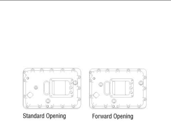
Shift Bar Housings
Two types of shift bar housings are available for this transmission. Both are described and shown below.
Standard
The standard shift bar housing has a gear shift lever opening that is located toward the rear of the transmission.
Forward
The forward shift bar housing has a gear shift lever opening located three inches closer to the transmission front than the standard opening. This forward design allows greater flexibility in mounting the transmission and is indicated by an "F" in the model number
.
Lubrication Pumps
Internal: An internal lubrication pump is located in the lower front of the transmission and is driven off the upper countershaft. Transmissions rated 1550 Lb·ft. and above include the internal pump standard.
PTO Driven: A PTO driven pump is externally mounted on the 6 or 8 bolt PTO openings and driven off the PTO gear.
Power Take Off (PTO) Usage
PTOs can be mounted in the following way:
6 or 8 Bolt: The 6 or 8 bolt openings are standard with the transmission. The PTO is mounted to the opening and driven from the PTO gear on the front countershaft.
Thru-Shaft: The thru-shaft PTO mounts on the rear of the transmission. It requires a special auxiliary housing and main case countershaft with internal splines.
6

Lubrication
Lubrication Specifications
 IMPORTANT
Transmission Filters should be changed during regular lube intervals. Inspection of the Transmission Filter should be conducted during preventive maintenance checks for damage or corrosion. Replace as necessary.
•For a list of Eaton® Approved Synthetic Lubricants, see TCMT0021 or call 1-800-826-HELP (4357).
•The use of lubricants not meeting these requirements will affect warranty coverage.
•Additives and friction modifiers must not be introduced. Never mix engine oils and gear oils in the same Transmission.
Transmission Operating Angles
If the Transmission operating angle is more than 12 degrees, improper lubrication will occur. The operating angle is the Transmission mounting angle in the Chassis plus the percent of upgrade (expressed in degrees). For operating angles over 12 degrees, the Transmission must be equipped with an Oil Pump or Cooler kit to insure proper lubrication.
Operating Temperatures with Oil Coolers
The Transmission must not be operated consistently at temperatures above 250 °F. Operation at temperatures above 250 °F [121 °C] causes loaded gear tooth temperatures to exceed 350 °F [177 °C] which will ultimately destroy the heat treatment of the gears. If the elevated temperature is associated with an unusual operating condition that will reoccur, a Cooler should be added, or the capacity of the existing cooling system increased.
The following conditions in any combination can cause operating temperatures of over 250 °F [121 °C]:
•Operating consistently at slow speed.
•High ambient temperatures.
•Restricted air flow around Transmission.
•Use of engine retarder.
•High horsepower operation.
Note: Transmission Coolers must be used to reduce the operating temperatures when the above conditions are encountered.
<![endif]>Information General
7

Lubrication
Oil Cooler Chart
Table 4
Transmission Oil Coolers are:
Recommended
•With engines of 350 H.P. and above. Required
•With engines 399 H.P. and above and GCW’s over 90,000 lbs.
•With engines 399 H.P. and above and 1400 lb-ft (1898.15 N•m) or greater torque.
•With engines 1500 lb-ft (2033.73 N•m) and above
18-speed AutoShift Transmissions require use of an Eaton® supplied Oil-to-Water Cooler or approved equivalent.
• With engines 450 H.P. and above.
8
Transmission Operation and Theory
Transmission Operation
Depending on specific model, this Fuller® transmission model contains from 9 to 15 forward gear ratios and three reverse gear ratios. The gear shift lever mechanically engages and disengages five forward gears and one reverse gear in the transmission front section. The rear section of the transmission (auxiliary section) contains three additional gear sets which are shifted with air. The auxiliary section provides deep reduction (low low range), low range, and high range. The driver can shift in or out of deep reduction by moving the deep reduction button found on the shift knob side. Low and high range are shifted by moving the range selection lever found on the shift knob front. Therefore, when a front section gear is combined with the proper auxiliary section condition (deep reduction, low range, or high range) a corresponding forward or reverse gear ratio is obtained. See the operating instructions and power flow charts found in this section for specific details.
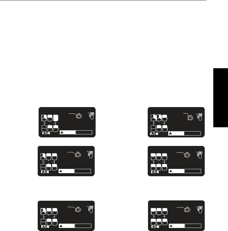
Shift Patterns
A shift pattern decal that explains how to properly shift the transmission should be in your vehicle (Figure 2-1). If it has been lost, a replacement may be obtained from any Eaton® parts distributor.
RTO-11707LL RTO-11707DLL RTO-13707MLL RTO-13707DLL
RTO-11708LL RTO-14708LL
RTX-11708LL RTX-14708LL RTO-11908LL RTO-14908LL RTO-16908LL
Eaton |
® |
Fuller |
¨ |
Roadranger |
¨ |
7 SPEED |
+LO & LO-LO (RTO) |
|
|||||
|
|
|
|
|
RANGE |
|
|||||||
Transmissions |
|
|
DEEP REDUCTION |
|
SELECTOR |
|
|||||||
|
|
SELECTOR |
|
|
|
|
|||||||
R R |
|
4 |
|
|
|
(LO-LO) |
|
|
HI |
|
|||
|
|
|
7 |
|
|
|
|
|
LO |
|
|||
R |
|
|
1 |
|
|
PRE-SELECT |
ALL RANGE SHIFTS |
|
|
||||
|
|
|
|
|
(MOVE RANGE SELECTOR BEFORE MOVING SHIFT LEVER) |
|
|||||||
|
|
|
|
|
|
|
UPSHIFTING |
|
|
|
|
||
|
|
Neutral |
|
|
|
START WITH RANGE SELECTOR DOWN |
|
|
|
||||
|
|
|
|
|
SHIFT LO-1-2-3 RAISE RANGE SELECTOR |
|
|
||||||
|
|
|
|
|
|
|
SHIFT 4-5-6 |
|
|
|
|
||
LO |
|
|
5 |
|
|
6 |
DOWNSHIFTING |
|
|
|
|||
|
|
|
|
SHIFT 3-2-1-LO |
|
|
|
|
|||||
|
|
|
|
|
|
|
SHIFT 7-6-5-4 MOVE RANGE SELECTOR DOWN |
|
|
||||
LO-LO |
|
|
2 |
|
|
3 |
DO NOT CHANGE RANGE WHILE MOVING IN REVERSE |
<![if ! IE]> <![endif]>20464 |
|||||
|
|
|
|
|
! |
WARNING |
PUT TRANSMISSION IN NEUTRAL |
||||||
|
|
|
|
|
|
|
|||||||
|
|
|
|
|
|
|
BEFORE STARTING ENGINE |
||||||
Eaton |
¨ |
Fuller |
¨ |
Roadranger |
¨ |
|
8 SPEED |
+LO & LO-LO (RTO) |
|
||||
|
|
|
|
|
|
RANGE |
|
||||||
Transmissions |
|
|
|
SELECTOR |
|
|
|
SELECTOR |
|
||||
|
|
|
|
|
|
|
DEEP REDUCTION |
|
|
||||
R R |
|
|
5 |
|
|
8 |
(LO-LO) |
|
|
|
HI |
|
|
|
|
|
|
|
|
|
|
|
LO |
|
|||
R |
|
|
1 |
|
|
4 |
PRE-SELECT |
|
ALL RANGE SHIFTS |
|
|
|
|
|
|
|
|
(MOVE RANGE SELECTOR BEFORE MOVING SHIFT LEVER) |
|
||||||||
|
|
|
|
|
|
|
UPSHIFTING |
|
|
|
|
|
|
|
Neutral |
|
|
|
START WITH RANGE SELECTOR DOWN |
|
|
|
|||||
|
|
|
|
SHIFT LO-1-2-3-4 RAISE RANGE SELECTOR |
|
|
|||||||
|
|
|
|
|
|
|
SHIFT 5-6-7-8 |
|
|
|
|
|
|
LO |
|
|
6 |
|
7 |
DOWNSHIFTING |
|
|
|
|
|||
|
|
|
SHIFT 4-3-2-1-LO |
|
|
|
|
||||||
|
|
|
|
|
|
|
SHIFT 8-7-6-5- MOVE RANGE SELECTOR DOWN |
|
|
||||
LO-LO |
|
|
2 |
|
3 |
DO NOT CHANGE RANGE WHILE MOVING IN REVERSE |
<![if ! IE]> <![endif]>20465 |
||||||
|
|
|
|
! |
WARNING |
PUT TRANSMISSION IN NEUTRAL |
|||||||
|
|
|
|
|
|
|
|||||||
|
|
|
|
|
|
|
BEFORE STARTING ENGINE |
||||||
Eaton |
¨ |
Fuller |
¨ |
Roadranger |
¨ |
8 SPEED |
+LO & LO-LO |
|
||
|
|
|
|
|
RANGE |
|
||||
Transmissions |
|
|
SELECTOR |
|
|
SELECTOR |
|
|||
|
|
|
|
|
DEEP REDUCTION |
|
|
|||
R R |
|
5 |
|
7 |
(LO-LO) |
|
|
HI |
|
|
|
|
|
|
|
|
LO |
|
|||
R |
|
1 |
|
3 |
PRE-SELECT |
ALL RANGE SHIFTS |
|
|
|
|
|
|
(MOVE RANGE SELECTOR BEFORE MOVING SHIFT LEVER) |
|
|||||||
|
|
|
|
|
UPSHIFTING |
|
|
|
|
|
|
Neutral |
|
|
START WITH RANGE SELECTOR DOWN |
|
|
|
|||
|
|
|
SHIFT LO-1-2-3-4 RAISE RANGE SELECTOR |
|
|
|||||
|
|
|
|
|
SHIFT 5-6-7-8 |
|
|
|
|
|
LO |
|
6 |
|
8 |
DOWNSHIFTING |
|
|
|
|
|
|
|
SHIFT 4-3-2-1-LO |
|
|
|
|
||||
|
|
|
|
|
SHIFT 8-7-6-5- MOVE RANGE SELECTOR DOWN |
|
|
|||
LO-LO |
|
2 |
|
4 |
DO NOT CHANGE RANGE WHILE MOVING IN REVERSE |
<![if ! IE]> <![endif]>22466 |
||||
|
|
|
! WARNING |
PUT TRANSMISSION IN NEUTRAL |
||||||
|
|
|
|
|
||||||
|
|
|
|
|
BEFORE STARTING ENGINE |
|||||
RTO-11709MLL RTO-14709MLL RTO-11909MLL RTO-14909MLL
RT-11715
RT-14715
RT-15715
RT-14915
RTX-11715
RTX-14715
RTX-15715
RTO-14915
RTO-16915
RTO-11715
RTO-14715
RTO-15715
Eaton |
¨ |
Fuller |
¨ Roadranger |
¨ |
|
9 SPEED +LO & LO-LO |
|
|||
Transmissions |
|
|
DEEP REDUCTION |
|
RANGE |
|
|
|||
|
|
|
SELECTOR |
|
|
|||||
R R |
|
1 5 |
7 |
|
SELECTOR |
|
IN |
|
|
|
|
|
(LO-LO) |
|
HI |
|
|||||
|
|
|
|
|
|
|
|
|
|
|
R |
|
LL2 |
3 |
|
|
|
|
OUT |
LO |
|
|
PRE-SELECT |
ALL RANGE SHIFTS |
|
|
||||||
|
|
|
|
|||||||
|
|
|
|
MOVE RANGE SELECTOR BEFORE MOVING SHIFT LEVER |
|
|
||||
|
Neutral |
|
UPSHIFTING |
|
|
|
|
|
||
|
|
START WITH RANGE SELECTOR DOWN |
|
|
||||||
|
|
|
|
SHIFT LO-1-2-3-4 RAISE RANGE SELECTOR |
|
|
||||
LO |
|
6 |
8 |
SHIFT 5-6-7-8 |
|
|
|
|
|
|
|
DOWNSHIFTING |
|
|
|
|
|
||||
|
SHIFT 8-7-6-5 MOVE RANGE SELECTOR DOWN |
|
|
|||||||
LL1 |
|
2 |
4 |
SHIFT 4-3-2-1-LO |
|
|
|
|
<![if ! IE]> <![endif]>4302441 |
|
|
DO NOT CHANGE RANGE WHILE MOVING IN REVERSE |
|
||||||||
|
|
|
||||||||
|
|
|
|
! WARNING |
PUT TRANSMISSION IN NEUTRAL |
|
||||
|
|
|
|
BEFORE STARTING ENGINE |
|
|
||||
Eaton |
¨ |
Fuller |
¨ Roadranger |
¨ |
|
|
15 SPEED (RT & RTX) |
|
||
Transmissions |
|
DEEP REDUCTION |
|
RANGE |
|
|
||||
|
|
SELECTOR |
|
|
||||||
|
|
|
|
SELECTOR |
|
|
|
|
|
|
HI |
|
7 |
9 |
(LO-LO) |
|
IN |
|
HI |
|
|
|
|
|
|
OUT |
|
LO |
|
|||
R |
|
2 |
4 |
PRE-SELECT |
ALL RANGE SHIFTS |
|
|
|||
LO |
|
(MOVE RANGE SELECTOR |
BEFORE MOVING SHIFT LEVER) |
|
|
|||||
|
|
|
|
UPSHIFTING |
|
|
|
|
|
|
|
Neutral |
|
START WITH RANGE SELECTOR DOWN |
|
|
|||||
|
|
SHIFT 1-2-3-4-5 RAISE RANGE SELECTOR |
|
|
||||||
|
|
|
|
SHIFT 6-7-8-9-10 |
|
|
|
|
|
|
6 |
|
8 |
10 |
DOWNSHIFTING |
|
|
|
|
|
|
|
SHIFT 5-4-3-2-1 |
|
|
|
|
|
||||
|
|
|
|
SHIFT 10-9-8-7-6 MOVE RANGE SELECTOR DOWN |
|
|
||||
1 |
|
3 |
5 |
DO NOT CHANGE RANGE WHILE MOVING IN REVERSE |
|
|
||||
|
! |
WARNING |
PUT TRANSMISSION IN NEUTRAL |
<![if ! IE]> <![endif]>20468 |
||||||
|
|
|
|
|||||||
|
|
|
|
BEFORE STARTING ENGINE |
||||||
Eaton |
¨ Fuller |
¨ Roadranger |
¨ |
15 SPEED |
(RTO) |
|
|||
Transmissions |
|
DEEP REDUCTION |
|
RANGE |
|
|
|||
|
|
SELECTOR |
|
|
|||||
|
|
|
SELECTOR |
|
|
|
|
||
HI |
7 |
10 |
(LO-LO) |
IN |
HI |
|
|||
|
|
OUT |
LO |
|
|||||
R |
2 |
5 |
PRE-SELECT ALL RANGE SHIFTS |
MOVING SHIFT LEVER) |
|
|
|||
LO |
(MOVE RANGE SELECTOR |
BEFORE |
|
|
|||||
|
|
|
UPSHIFTING |
|
|
|
|
||
|
Neutral |
|
START WITH RANGE SELECTOR DOWN |
|
|
|
|||
|
|
SHIFT 1-2-3-4-5 RAISE RANGE SELECTOR |
|
|
|
||||
|
|
|
SHIFT 6-7-8-9-10 |
|
|
|
|
||
6 |
8 |
9 |
DOWNSHIFTING |
|
|
|
|
||
SHIFT 10-9-8-7-6 MOVE RANGE SELECTOR DOWN |
|
|
|||||||
SHIFT 5-4-3-2-1 |
|
|
|
|
|||||
1 |
3 |
4 |
DO NOT CHANGE RANGE WHILE MOVING IN REVERSE |
|
|
||||
! |
WARNING |
PUT TRANSMISSION IN NEUTRAL |
<![if ! IE]> <![endif]>20467 |
||||||
|
|
|
|||||||
|
|
|
BEFORE STARTING ENGINE |
|
|||||
Figure 2-1. Shift Pattern Decal
<![endif]>Information General
9
Transmission Operation and Theory
Initial Start-Up
 WARNING
Before starting a vehicle always be seated in the driver’s seat, move the shift lever to neutral, and set the parking brakes.
 CAUTION
Before moving a vehicle, make sure you understand the shift pattern configuration.
1.Make sure the shift lever is in neutral and the parking brakes are set.
2.Turn on the key switch, and start the engine.
3.Allow the vehicle air pressure to build to the correct level. Refer to your “Operator and Service Manual” supplied with the truck.
4.Apply the service brakes.
5.Release the parking brakes on the vehicle.
6.Make sure the Range Selector is down in the low range position (Figure 2-2).
Range Selector MUST be in the Low Range position for Low Range.
Figure 2-2.
7.Depress the clutch pedal to the floor.
8.Move the shift lever to the desired initial gear.
9.Slowly release the clutch pedal and apply the accelerator.
Double-Clutching Procedure
1.Depress the pedal to disengage the clutch.
2.Move the shift lever to neutral.
3.Release the pedal to engage the clutch.*
a.Upshifts—decelerate engine until engine RPM and road speed match.
b.Downshifts—accelerate engine until engine RPM and road speed match.
4.Quickly depress the pedal to disengage the clutch and move the shift lever to the next gear speed position.
5.Release the pedal to engage the clutch.
Note: By engaging the clutch with the shift lever in the neutral position, the operator is able to control the mainshaft gear RPM since it is regulated by engine RPM. This procedure allows the operator to
10
Transmission Operation and Theory
speed up or slow down the mainshaft gearing to properly match the desired gear speed and the
outputshaft speed.
Lever Shifts
When moving the shift lever, double-clutching is recommended.
Range Shifts
 CAUTION
Avoid moving the Range Selector with the shift lever in neutral while the vehicle is moving.
Low range to high range
When in the last gear position for low range and ready for the next upshift, preselect by moving the range selector lever up. The move the shift lever, double-clutch, to the next higher speed position according to your shift pattern. As the shift lever passes through neutral, the transmission will automatically shift from low to high range.
High range to low range
While still in gear, preselect for low by moving the range selector down. Then move the shift lever, double-clutching, to the next desired gear position in low range. As the shift lever passes through neutral, the transmission automatically shifts from high range to low range.
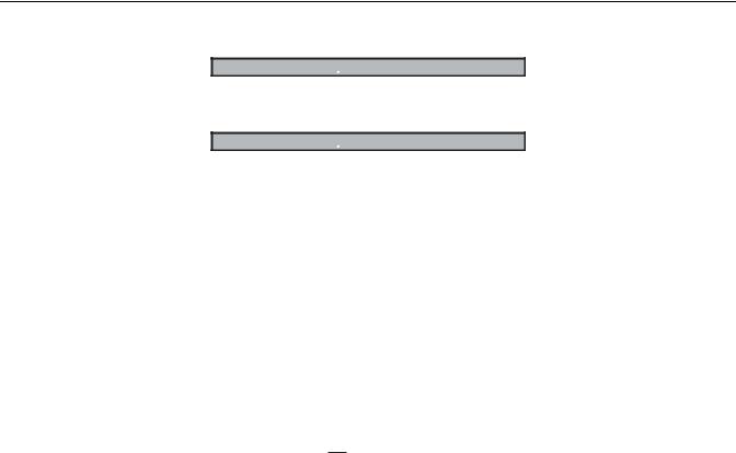
Deep Reduction Shifts
Note: Deep reduction is only available in low range.
Button back - deep reduction not selected.
F u lle r ¨
T ransmissions
Button forward - deep reduction selected
F u lle r ¨
T ransmissions
To obtain deep reduction (low low), first make sure range selection lever is down for low range. Then, move deep reduction button forward.
Upshifts
An upshift from deep reduction can be performed while the vehicle is moving.
If the driver is not moving the shift lever during the shift (example: RTO-14708LL) depress the clutch pedal once immediately after moving the deep reduction button rearward. Decrease engine RPM to obtain synchronous for shift completion.
If the driver is moving the shift lever during the shift (example: RTO-14715) move the deep reduction button rearward and immediately double-clutch while moving the shift lever. Decrease engine RPM to obtain synchronous for shift completion.
<![endif]>Information General
11
Transmission Operation and Theory
Downshifts
Downshifts into deep reduction while moving are generally not recommended, but are possible if operating conditions make it necessary. In this situation, complete the shift immediately after moving the deep reduction button. Single clutch if not moving the shift lever, double-clutch if the shift lever will be moved.
Special Notes
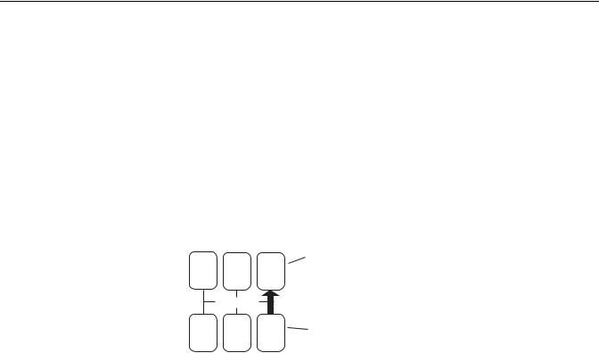
15 Speed Models
When upshifting from a deep reduction gear into a low range gear, it is recommended that the shift lever is moved back one gear position during the shift out of deep reduction. For example:
If the driver is in deep reduction 5th gear position, he/she should double-clutch and move the shift lever to the 4th gear position immediately after moving the deep reduction button. If the shift lever is not moved during this shift, the vehicle must have enough speed to make a 42% step upshift.
R |
|
4 |
4th Gear Position |
|
1 |
Low Range |
|||
|
|
|||
|
Neutral |
|
|
|
|
|
5 |
5th Gear Position |
|
|
|
|
Deep Reduction |
DLL and MLL Models
The three lowest gears (LL1, LO, LL2) are used for road speed control. These shifts are not intended to be used as progressive shifts.
Additional Operating Information
Preselect
IMPORTANT: Always preselect all range shifts when upshifting or downshifting. Preselection requires that the Range Selector is moved to the needed position before starting the lever shift. Preselected range shifts are completed automatically as the lever is moved through neutral and into the next gear. Preselecting all range shifts prevents damage to the transmission and provides for smoother shifts.
Clutch Brake (Used with pull-type clutches)
The Clutch Brake is applied by fully depressing the clutch pedal to the floor board. When applied, the brake slows down and can stop the transmission front box gearing. It is a disc-type brake incorporated into the clutch and transmission drive gear assemblies. Never use the Clutch Brake when upshifting or downshifting. Use only for initial gear engagement when the vehicle is standing still.
Countershaft Brake (Used with push-type clutches)
The control button is mounted on the shift lever just below the shift knob. To operate the brake, disengage the clutch, press down the control button, and shift into 1st or reverse. This is an air operated mechanical brake which slows down the transmission gearing by forcing a piston against the countershaft PTO gear
Note: Never use the Countershaft Brake when upshifting or downshifting. Use only for initial gear engagement when the vehicle is standing still.
12

Recommended Tools
Tool Specifications
Some repair procedures pictured in this Manual show the use of specialized tools. Their actual use is recommended as they make Transmission repair easier, faster, and prevent costly damage to critical parts.
For the most part, ordinary Mechanic's Tools such as Socket Wrenches, Screwdrivers, etc., and other standard shop items such as a Press, Mauls and Soft Bars are the only tools needed to successfully disassemble and reassemble any Fuller® Transmission.
The following tables list and describe the typical tools required to properly service this model Transmission above and beyond the necessary basic Wrenches, Sockets, Screwdrivers, and Pry Bars.
General Tools
The following tools are available from several Tool Manufacturers such as Snap-On, Mac, Craftsman, OTC, and many others:
Tool |
Purpose |
|
|
|
|
|
|
|
0–100 lb-ft 1/2" drive Torque Wrench |
General torquing of fasteners (Typically 15–80 lb-ft |
|
[20.34–108.47 N•m]) |
||
|
||
|
|
|
0–700 lb-ft 3/4" or 1" drive Torque Wrench |
Torquing of Output Nut to 650–700 lb-ft (881.28–949.07 N•m) |
|
|
|
|
0–50 lb-in 3/8" drive Torque Wrench |
General torquing of fasteners |
|
|
|
|
0–30 lb-in 1/4" drive Torque Wrench |
Torquing of Cap Screws to 7 lb-in (0.79 N•m) during Auxiliary Countershaft |
|
Bearing endplay setting procedure |
||
|
||
|
|
|
70 MM or 2 2/4" Socket - Standard Depth |
To remove the Output Shaft Nut |
|
|
|
|
Snap Ring Pliers - Large Standard External |
To remove the Snap Rings at the Auxiliary Drive Gear, Input Shaft Bearing, |
|
and Countershaft Bearings |
||
|
||
|
|
|
Feeler Gauges |
To set Mainshaft Washer Endplay and Auxiliary Tapered Bearing Endplay |
|
|
|
|
Rolling Head Pry Bar |
To remove the Auxiliary Drive Gear Bearing |
|
|
|
|
(2) Air Pressure Gauges 0–100 PSI (0–1034 kPa) |
To troubleshoot and verify correct operation of Air System |
|
|
|
|
Universal Bushing Driver |
To remove and install Clutch Housing Bushings. Bushing |
|
OD = 1.125 in., ID = 1.000 in. |
||
|
||
|
|
<![endif]>Information General
9

Recommended Tools
Special Tools
The following Transmission Tools are available directly from K-Line Industries. To obtain any of these tools listed, contact K-Line by phone or visiting the online store.
K-Line Industries, Inc.
315 Garden Avenue
Holland, MI 49424
1-800-824-KLINE (5546) http://www.klineind.com/
K-Line Part # |
Tool |
Tool Description |
|
|
|
|
|
|
|
|
|
RR1001TR-1 |
Driver - Output Seal Slinger |
Used to install Output Seal Protective Slinger on FR & RT-Series |
|
(Gen 9) Transmission Output Yokes. |
|||
|
|
||
|
|
|
|
RR1001TR-2 |
Driver - Output Seal |
Used to install Output Seal in Rear Bearing Cover on RT-Series |
|
(Gen 6 & 7) Transmissions with 2.75" Output Shaft. |
|||
|
|
||
|
|
|
|
RR1001TR-4 |
Driver - Output Seal Slinger |
Used to install Output Seal Protective Slinger on RT-Series (Gen 6 & |
|
7) Transmission Output Yokes. |
|||
|
|
||
|
|
|
|
RR1001TR-8 |
Driver - Output Seal |
Used with Seal Driver RR1001TR-2 to install Output Seal in Rear |
|
Bearing Cover on FR & RT-Series (Gen 9) Transmissions. |
|||
|
|
||
|
|
|
|
RR1002TR |
Auxiliary Countershaft Support Straps |
Used to support the aux-Countershaft Assemblies when servicing the |
|
aux-section on FR & RT-Series (Gen 7 & 9) Transmissions. |
|||
|
|
||
|
|
|
|
RR1004TR |
Mainshaft Lifting Hook |
Used to remove/install Mainshaft Assembly into the Transmission |
|
Main Case. |
|||
|
|
||
|
|
|
|
RR1005TR |
Driver - Input Bearing |
Used to install the Input Bearing on Transmissions with 2" & 1.75" |
|
Input Shafts. |
|||
|
|
||
|
|
|
|
RR1006TR |
Auxiliary Section Lifting Bracket |
Used to lift Transmission Auxiliary Sections. |
|
|
|
|
|
RR1007TR |
Shimming Gauge - Auxiliary |
Used for setting proper Auxiliary Countershaft Bearing clearance on |
|
Countershaft (0.100") |
FR-Series and RT-Series (Gen 7 & 9) Transmissions. |
||
|
|||
|
|
|
|
RR1010TR |
Slide Hammer |
Used to remove Bearing Races, Reverse Idler Shafts, and Seals. |
|
|
|
|
|
RR1011TR-1 |
Slide Hammer Attachment |
Used for removing Output Seals. |
|
|
|
|
|
RR1011TR-2 |
Slide Hammer Attachment |
Used for removing Bearing Races from the Transmission Case. |
|
|
|
|
|
RR1011TR-3 |
Slide Hammer attachment |
Used for removing Bearing Races from the Transmission Case. |
|
|
|
|
|
RR1012TR-2 |
Driver - Countershaft Front Bearings |
Used to install Front Countershaft Bearings on RT-Series |
|
Transmissions. |
|||
|
|
||
|
|
|
|
RR1012TR-3 |
Puller - Countershaft Front Bearings |
Used to remove Front Countershaft Bearings on RT-Series |
|
Transmissions. |
|||
|
|
||
|
|
|
|
RR1012TR-4 |
Driver - Countershaft Rear Bearings |
Used to install Rear Countershaft Bearings, RT-Series Transmissions. |
|
|
|
|
|
RR1012TR-5 |
Driver - Auxiliary Countershaft |
Used to install Auxiliary Countershaft Bearings on FR & RT-Series |
|
Bearings |
Transmissions with Auxiliary Section helical gearing. |
||
|
|||
|
|
|
|
RR1012TR-6 |
Driver - Auxiliary Countershaft |
Used to install Auxiliary Countershaft Bearings on RT-Series |
|
Bearings |
Transmissions with Auxiliary Section spur gearing. |
||
|
|||
|
|
|
|
RR1013TR |
Timing Block - RT-Series Countershaft |
Used to support the Upper Countershaft during Main Box assembly on |
|
|
|
RT-Series Transmissions. |
10
|
|
Recommended Tools |
|
|
|
|
|
|
|
|
|
|
|
|
K-Line Part # |
Tool |
Tool Description |
|
<![if ! IE]> <![endif]>General |
|
|
|
|
|
RR1015TR |
Driver - Countershaft Front/Rear |
Used to install Front and Rear Countershaft Bearings on FR-Series |
|
|
|
|
|||
bearings |
Transmissions. |
|
|
|
|
|
|
||
|
|
|
|
<![if ! IE]> <![endif]>Information |
RR1017TR |
Pusher - Countershaft |
Used to push the Countershaft Assembly rearward to create clearance |
|
|
|
|
|||
for Bearing Puller on FR & RT-Series Transmissions. |
|
|
||
|
|
|
|
|
|
|
|
|
|
RR1019TR |
Hand Maul |
Used with Bearing and Seal Drivers for part installation/removal. |
|
|
|
|
|
|
|
RR1020TR |
Soft Bar |
Used with hand Maul to remove parts from the Transmission. |
|
|
|
|
|
|
|
RR1022TR |
Countershaft Support Tool |
Used to support the Upper Countershaft during Main Box disassembly |
|
|
on FR & RT-Series Transmissions. |
|
|
||
|
|
|
|
|
|
|
|
|
|
RR1023TR |
Puller - Input Bearing |
Used to remove the Input Bearing on FR & RT-Series Transmissions. |
|
|
|
|
|
|
|
RR1024TR |
Driver - Output Bearing |
Used to install the Output Bearing on FR & RT-Series Transmissions. |
|
|
|
|
|
|
|
Shop Equipment
Tool |
Purpose |
|
|
|
|
20 Ton capacity Press |
To press Countershaft Gears from Countershaft. |
|
|
Eaton Aftermarket Parts
The following tools are available through Eaton Aftermarket Parts. To obtain any of the tools listed, contact your local Eaton Parts Distributor.
Tool |
Purpose |
Eaton Part Number |
|
|
|
|
|
|
|
|
|
5/32" Air Line Release Tool |
To remove 5/32" Air Lines from Push-to- |
P/N 4301157 included in Kit K-2394 |
|
|
Connect Fittings. |
|
|
|
|
|
|
Air Line Cutting Tool |
To cut plastic Air Lines smoothly and |
P/N 4301158 included in Kit K-2394. |
|
squarely. |
|||
|
|
||
|
|
|
11
Preventive Maintenance
Preventive Maintenance Inspection
Everyday there are countless vehicles operating over the highways with Transmissions in such a neglected mechanical condition, they can be referred to as failures looking for a place to break down. They lack a proper and organized preventive
maintenance program.
Preventive maintenance is a general term which applies to all procedures necessary to have maximum life and satisfactory service at the lowest possible cost, short of removing and repairing the unit.
A number of conditions contrary to good preventive maintenance can generally be pointed to when inspecting a failed Transmission. Taking a few minutes every so many hours or miles to do a few simple checks could help avoid eventual breakdown or reduce the repair cost. If the Transmission is not cared for, it will breakdown.
Preventative Maintenance Check Points
Note: Transmission appearance may differ, however the procedure is the same.
<![endif]>Information General
13

Preventive Maintenance
1.Air System and Connections
•Check for leaks, worn Air Lines, loose connections and Cap Screws.
2.Clutch Housing Mounting
•Check all Cap Screws of Clutch Housing flange for looseness.
3.Clutch Release Bearing (Not Shown)
•Remove Hand Hole Cover and check Radial and Axial Clearance in Release Bearing.
•Check relative position of thrust surface of Release Bearing with Thrust Sleeve on Push-type Clutches.
4.Clutch Pedal Shaft and Bores
•Pry upward on Shafts to check wear.
•If excessive movement is found, remove Clutch Release Mechanism and check Bushings on Bores and wear on Shafts. See OEM literature.
5.Lubricant
•See Lubrication Manual TCMT0021.
6.Oil Filter
•Oil Filter Inspection (during vehicle PM schedule):
-Inspect Oil Filter for damage or rust. Replace as necessary.
-Inspect Oil Filter Adapter for damage or leakage. Replace as necessary.
•Oil Filter Replacement
-Replace every 100,000 miles and top off fluid.
-Every Transmission fluid change.
7.Filler and Drain Plugs
•Remove Filler Plugs and check level of lubricant at specified intervals. Tighten fill and Drain Plugs securely.
8.Cap Screws and Gaskets
•For applicable models, check all Cap Screws, especially those on PTO Covers and Rear Bearing Covers for looseness which would cause oil leakage.
•Check PTO opening and Rear Bearing Covers for oil leakage due to faulty Gasket.
9.Gear Shift Lever
•Check for looseness and free play in Housing. If Lever is loose in Housing, proceed with Check No. 10.
10.Gear Shift Lever Housing Assembly
•If present, remove Air Lines at Air Valve or Slave Valve. Remove the Gear Shift Lever Housing Assembly from the Transmission.
•Check the Tension Spring and Washer for set and wear.
•Check the Gear Shift Lever Spade Pin and slot for wear.
•Check bottom end of Gear Shift Lever for wear and check slot of Yokes and Blocks in Shift Bar Housing for wear at contact points with Shift Lever.
Checks With Drive Line Dropped
11.Universal Joint Companion Flange or Shaft Nut
•Check for tightness. Tighten to recommended torque.
12.Output Shaft (Not Shown)
•Pry upward against Output Shaft to check radial clearance in Mainshaft Rear Bearing.
14

Preventive Maintenance
Checks With Universal Joint Companion Flange or Yoke Removed
Note: If necessary, use solvent and shop rag to clean sealing surface of Companion Flange or Yoke. Do not use Crocus Cloth, Emery Paper, or other abrasive materials that will mar surface finish.
13.Splines on Output Shaft (Not Shown)
•Check for wear from movement and chucking action of the Universal Joint Companion Flange or Yoke.
14.Mainshaft Rear Bearing Cover (Not Shown)
•Check Oil Seal for wear.
Inspection
Part to Inspect |
What to Check For |
Action to be Done |
|
|
|
|
|
|
|
|
|
|
Speedometer Cables should not be |
Applied hydraulic Thread Sealant #71208 to threads, |
|
|
torque Speedometer Sleeve to 35–50 lb-ft |
||
|
loose. |
||
|
(47.45–67.79 N•m). |
||
Speedometer Connections |
|
||
|
|
||
Should be an O-Ring or gasket between |
|
||
|
|
||
|
the mating Speedometer Sleeve and the |
Replace the O-Ring/gasket if damaged or missing. |
|
|
Rear Bearing Cover. |
|
|
|
|
|
|
|
Check Retaining Cap Screws for |
Apply Eaton Sealant #71205 to the Cap Screw |
|
|
tightness. |
threads, torque to 35–45 lb-ft (47.45–61.01 N•m). |
|
|
|
|
|
Rear Bearing Cover Cap |
Verify Nylon Collar and Gasket are |
Use new parts if need to replace. Apply Eaton |
|
installed at the chamfered hole, aligned |
|||
Screws, Gasket, and Nylon |
Sealant #71205 to the Cap Screw threads, torque to |
||
near the mechanical Speedometer |
|||
Collar |
35–45 lb-ft (47.45–61.01 N•m). |
||
opening. |
|||
|
|
||
|
|
|
|
|
Verify that a Rear Bearing Cover gasket |
Install a new Gasket if Rear Bearing Cover was |
|
|
is in place. |
removed. |
|
|
|
|
|
|
Check the Output Shaft Nut for |
Torque the Output Shaft Nut to 650–700 lb-ft |
|
Output Shaft Nut |
(881.28–949.07 N•m). Do not over torque the |
||
tightness. |
|||
|
Output Nut. |
||
|
|
||
|
|
|
|
|
|
Apply Eaton Sealant #71205 to the Cap Screw |
|
PTO Covers and Openings |
Check the Cap Screws for tightness. |
threads. Torque 6 bolt PTO Cap Screws to |
|
35–45 lb-ft (47.45–61.01 N•m), 8 bolt PTO Cap |
|||
|
|
||
|
|
Screws to 50–65 lb-ft (67.79–88.13 N•m). |
|
|
|
|
|
|
Check Front Bearing Cover, Front Case, |
|
|
Gray Iron Parts |
Shift Bar Housing, Rear Bearing Cover, |
Replace parts found to be damaged. |
|
and Clutch Housing for cracks or |
|||
|
|
||
|
breaks. |
|
|
|
|
|
|
|
Check return threads for damage. |
If threads damaged, replace the Input Shaft. |
|
Front Bearing Cover |
|
|
|
Check the Cap Screws for tightness. |
Torque the Cap Screws to 35–45 lb-ft |
||
|
(47.45–61.01 N•m). |
||
|
|
||
|
|
|
|
Oil Cooler and Oil Filter |
Check all connectors, Fittings, Hoses, |
Tighten any loose Fittings. |
|
and Filter Element for tightness. |
|||
|
|
||
|
|
|
|
|
Check the Oil Drain Plug and the Oil Fill |
Torque the Oil Drain Plug to 45–55 lb-ft |
|
Oil Drain Plug, Oil Fill Plug |
(61.01–74.57 N•m), Oil Fill Plug to 60–70 lb-ft |
||
Plug for leakage. |
|||
|
(81.35–94.91 N•m). |
||
|
|
||
|
|
|
<![endif]>Information General
15
Preventive Maintenance
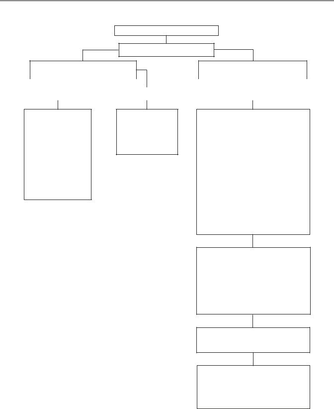
Oil Leak Inspection Process
Inspect for Oil Leak
Determine if it is a Weep or a Leak
Weep: Stained, damp, no drips, light oil film, dirt adhered to the contaminated area.
Leak: Extremely wet or dripping of oil in the contaminated area.
|
|
|
|
|
|
|
|
|
|
|
|
Gasket |
|
|
Rear Seal |
|
|
Leak |
|
||
|
|
|
|
|
|
|
|
|
|
|
Step 1
1.Clean suspected oil weep area with a clean dry cloth or mild soluble degreaser.
2.Ensure lube is to proper level.
3.Notify the customer that it is only a weep and it is not considered to be detrimental
to the life of the transmission.
4.Repair is complete.
1.Do not repair: Rear seal is designed to allow minimal seepage.
2.Ensure lube is to proper level.
1.Determine the origin of the leak path.
2.If origin of leak is obvious skip to Step 3.
3.If the origin of the oil leak is not obvious then use either of the two following steps to determine the oil leak:
Note: Do not use a high pressure spray washer to clean the area. Use of a high pressure spray may force contamination into the area of concern and temporarily disrupt the leak path.
i.Clean area with a clean dry cloth or mild soluble degreaser and fill the transmission to the proper lube level.
OR
ii.Clean the area as noted above and insert tracer dye into the transmission lube and fill transmission to proper lube level.
Step 2
Operate vehicle to normal transmission operating temperature and inspect the area for oil leak(s) visually or if tracer dye was introduced use an UVL
(Ultraviolet Light) to detect the tracer dye’s point of origin.
Note: When inspecting for the origin of the leak(s) make sure the assumed leak area is not being contaminated by a source either forward or above the identified area such as the engine, shift tower, shift bar housing, top mounted oil cooler, etc...
Step 3
Once the origin of the leak is identified, repair the oil leak using proper repair procedures from the designated model service manual.
Step 4
After the repair is completed, verify the leak is repaired and operate the vehicle to normal transmission operating temperature. Inspect repaired area to ensure oil leak has been eliminated. If the leak(s) still occurs, repeat steps or contact the Roadranger Call Center
at 1-800-826-4357.
16
Power Flow
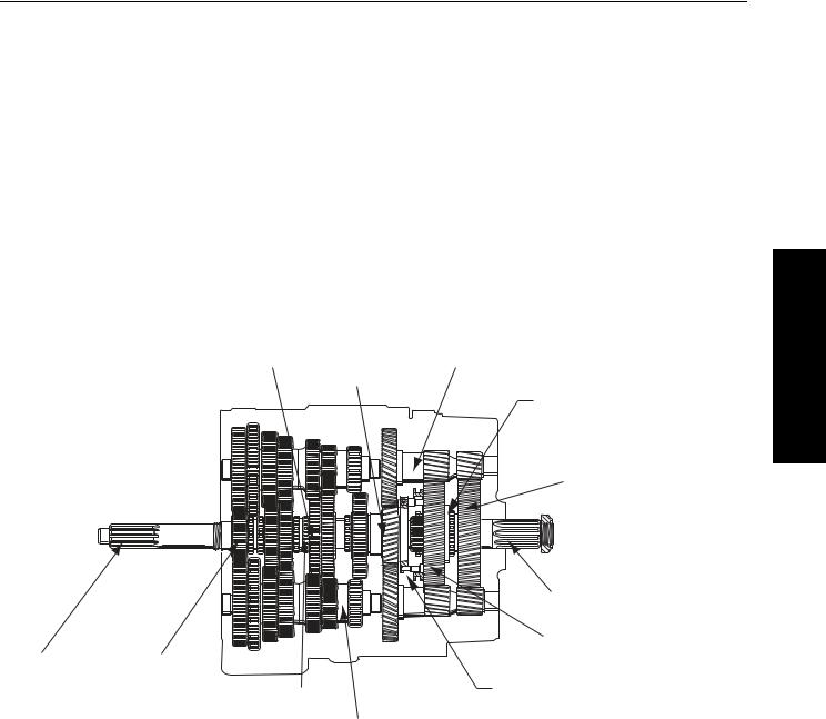
Power Flow Diagrams
An understanding of the engine’s power flow through a transmission in each particular gear will assist the technician in troubleshooting and servicing a transmission.
The Fuller® transmission can be thought of as two separate “transmissions” combined into one unit. The first “transmission” or front section contains six gear sets which are shifted with the gear shift lever. The second “transmission” called the auxiliary section, contains two gear sets and is shifted with air pressure.
Note: This transmission is referred to as a constant mesh type transmission. When in operation, all gears are turning even though only some of them are transferring power.
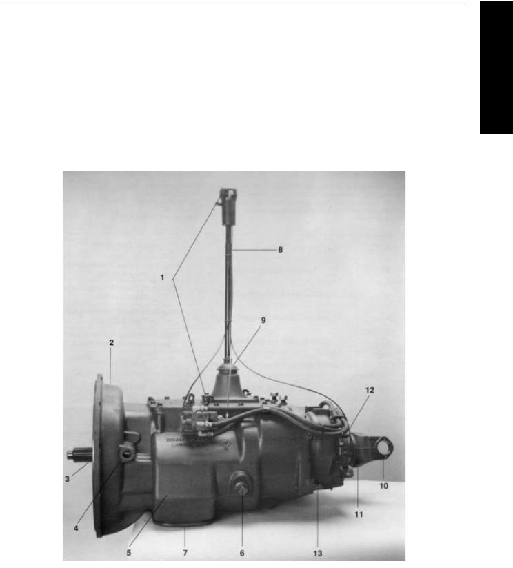
The illustration below shows the transmission with the main components called out. Note that the transmission is in the neutral position because the sliding clutches are all in their center positions and not engaged in any gears.
Mainshaft Gear |
Auxiliary Countershaft |
|
Auxiliary Drive Gear |
|
Deep-Reduction |
|
Sliding Clutch |
|
Auxiliary Deep-Reduction Gear |
|
|
Output Shaft |
|
|
Auxiliary Range Gear |
Input Shaft |
Mainshaft Gear |
|
|
Sliding Clutch |
Range Sliding Clutch |
|
|
|
|
|
Countershaft |
<![endif]>Information General
21
Power Flow
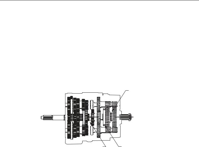
Front Section Power Flow
Note: The heavy lines in Figure 2-4 outline the power flow description below. For help in understanding the transmission components, refer to Figure 2-3.
1.Power (torque) from the vehicle’s engine is transferred to the transmission’s input shaft.
2.The input shaft rotates the main drive gear through internal splines in the hub of the gear
3.The main drive gear meshes with both countershaft driven gears and the torque is split between both countershafts
4.Because the countershaft gears are in constant mesh with the mainshaft gears, all the front section gearing rotates. However, only the engaged or selected mainshaft gear will have torque. External clutching teeth on the sliding clutch will engage internal clutching teeth on the selected mainshaft gear. Torque will now be provided from both opposing countershaft gears, into the engaged mainshaft gear, and through the sliding clutch to the front section mainshaft
5.The rear of the front section mainshaft is splined into the auxiliary drive gear and torque is now delivered to the auxiliary section.
Deep Reduction
Sliding Clutch Rearward
|
|
|
|
|
|
|
|
|
|
|
|
|
|
|
|
|
|
|
|
|
|
|
|
|
|
|
|
|
|
|
|
|
|
|
|
|
|
|
|
|
|
|
|
|
|
|
|
|
|
|
|
|
|
|
|
|
|
|
|
|
|
|
|
|
|
|
|
|
|
|
|
|
|
|
|
|
|
|
|
|
|
|
|
|
|
|
|
|
|
|
|
|
|
|
|
|
|
|
|
|
|
|
|
|
|
|
|
|
|
|
|
|
|
|
|
|
|
|
|
|
|
|
|
|
|
|
|
|
|
|
|
|
|
|
|
|
|
|
|
|
|
|
|
|
|
|
|
|
|
|
|
|
|
|
|
|
|
|
|
|
|
|
|
|
|
|
|
|
|
|
|
|
|
|
|
|
|
|
|
|
|
|
|
|
|
|
|
|
|
|
|
|
|
|
|
|
|
|
|
|
|
|
|
|
|
|
|
|
|
|
|
|
|
|
|
|
|
|
|
|
|
|
|
|
|
|
|
|
|
|
|
|
|
|
|
|
|
|
|
|
|
|
|
|
|
|
|
|
|
|
|
|
|
|
|
|
|
|
|
|
|
Range Sliding Clutch Rearward |
||
|
|
|
|
|
|
|
|
|
|
|
|
|
|
|
|
|
|
|
|
|
|
|
|
|
|
|
|
|
|
|
|
|
|
|
|
|
|
|
|
|
|
|
|
|
|
|
|
|
|
|||
|
|
|
|
|
|
|
|
|
|
|
|
|
|
|
|
|
|
|
|
|
|
|
|
|
|
|
|
|
|
|
|
|
|
|
|
|
|
|
|
|
|
|
|
|
|
|
|
|
|
|||
|
|
|
|
|
|
|
|
|
|
|
|
|
|
|
|
|
|
|
|
|
|
|
|
|
|
|
|
|
|
|
|
|
|
|
|
|
|
|
|
|
|
|
|
|
|
|
|
|
|
|||
|
|
|
|
|
|
|
|
|
|
|
|
|
|
|
|
|
|
|
|
|
|
|
|
|
|
|
|
|
|
|
|
|
|
|
|
|
|
|
|
|
|
|
|
|
|
|
|
|
|
|||
|
|
|
|
|
|
|
|
|
|
|
|
|
|
|
|
|
|
|
|
|
|
|
|
|
|
|
|
|
|
|
|
|
|
|
|
|
|
|
|
|
|
|
|
|
|
|
|
|
|
|||
|
|
|
|
|
|
|
|
|
|
|
|
|
|
|
|
|
|
|
|
|
|
|
|
|
|
|
|
|
|
|
|
|
|
|
|
|
|
|
|
|
|
|
|
|
|
|
|
|
|
|||
|
|
|
|
|
|
|
|
|
|
|
|
|
|
|
|
|
|
|
|
|
|
|
|
|
|
|
|
|
|
|
|
|
|
|
|
|
|
|
|
|
|
|
|
|
|
|
|
|
|
|||
|
|
|
|
|
|
|
|
|
|
|
|
|
|
|
|
|
|
|
|
|
|
|
|
|
|
|
|
|
|
|
|
|
|
|
|
|
|
|
|
|
|
|
|
|
|
|
|
|
|
|||
|
|
|
|
|
|
|
|
|
|
|
|
|
|
|
|
|
|
|
|
|
|
|
|
|
|
|
|
|
|
|
|
|
|
|
|
|
|
|
|
|
|
|
|
|
|
|
|
|
|
|||
|
|
|
|
|
|
|
|
|
|
|
|
|
|
|
|
|
|
|
|
|
|
|
|
|
|
|
|
|
|
|
|
|
|
|
|
|
|
|
|
|
|
|
|
|
|
|
|
|
|
|||
|
|
|
|
|
|
|
|
|
|
|
|
|
|
|
|
|
|
|
|
|
|
|
|
|
|
|
|
|
|
|
|
|
|
|
|
|
|
|
|
|
|
|
|
|
|
|
|
|
|
|||
|
|
|
|
|
|
|
|
|
|
|
|
|
|
|
|
|
|
|
|
|
|
|
|
|
|
|
|
|
|
|
|
|
|
|
|
|
|
|
|
|
|
|
|
|
|
|
|
|
|
|||
|
|
|
|
|
|
|
|
|
|
|
|
|
|
|
|
|
|
|
|
|
|
|
|
|
|
|
|
|
|
|
|
|
|
|
|
|
|
|
|
|
|
|
|
|
|
|
|
|
|
|||
|
|
|
|
|
|
|
|
|
|
|
|
|
|
|
|
|
|
|
|
|
|
|
|
|
|
|
|
|
|
|
|
|
|
|
|
|
|
|
|
|
|
|
|
|
|
|
|
|
|
|||
|
|
|
|
|
|
|
|
|
|
|
|
|
|
|
|
|
|
|
|
|
|
|
|
|
|
|
|
|
|
|
|
|
|
|
|
|
|
|
|
|
|
|
|
|
|
|
|
|
|
|||
|
|
|
|
|
|
|
|
|
|
|
|
|
|
|
|
|
|
|
|
|
|
|
|
|
|
|
|
|
|
|
|
|
|
|
|
|
|
|
|
|
|
|
|
|
|
|
|
|
|
|||
|
|
|
|
|
|
|
|
|
|
|
|
|
|
|
|
|
|
|
|
|
|
|
|
|
|
|
|
|
|
|
|
|
|
|
|
|
|
|
|
|
|
|
|
|
|
|
|
|
|
|||
|
|
|
|
|
|
|
|
|
|
|
|
|
|
|
|
|
|
|
|
|
|
|
|
|
|
|
|
|
|
|
|
|
|
|
|
|
|
|
|
|
|
|
|
|
|
|
|
|
|
|||
|
|
|
|
|
|
|
|
|
|
|
|
|
|
|
|
Sliding Clutch Forward |
|
|
|
|
|
|
|
|
|
|
|
|
||||||||||||||||||||||||
Figure 2-4. Front Section Power Flow
22
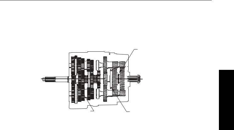
Power Flow
Front Section Power Flow - Direct Gear
In direct gear, the front sliding clutch is moved forward and engages into the back of the main drive gear. Torque will flow from the input shaft to the main drive gear, main drive gear to sliding clutch, sliding clutch straight into the front section mainshaft which delivers the torque to the auxiliary drive gear. See Figure 2- 5.
Note: All countershaft and mainshaft gears will rotate, but the gears will not be loaded.
Deep Reduction
Sliding Clutch Forward
|
|
|
|
|
|
|
|
|
|
|
|
|
|
|
|
|
|
|
|
|
|
|
|
|
|
|
|
|
|
|
|
|
|
|
|
|
|
|
|
|
|
|
|
|
|
|
|
|
|
|
|
|
|
|
|
|
|
|
|
|
|
|
|
|
|
|
|
|
|
|
|
|
|
|
|
|
|
|
|
|
|
|
|
|
|
|
|
|
|
|
|
|
|
|
|
|
|
|
|
|
|
|
|
|
|
|
|
|
|
|
|
|
|
|
|
|
|
|
|
|
|
|
|
|
|
|
|
|
|
|
|
|
|
|
|
|
|
|
|
|
|
|
|
|
|
|
|
|
|
|
|
|
|
|
|
|
|
|
|
|
|
|
|
|
|
|
|
|
|
|
|
|
|
|
|
|
|
|
|
|
|
|
|
|
|
|
|
|
|
|
|
|
|
|
|
|
|
|
|
|
|
|
|
|
|
|
|
|
|
|
|
|
|
|
|
|
|
|
|
|
|
|
|
|
|
|
|
|
|
|
|
|
|
|
|
|
|
|
|
|
|
|
|
|
|
|
|
|
|
|
|
|
|
|
|
|
|
|
|
|
|
|
|
|
|
|
|
|
|
|
|
|
|
|
|
|
|
|
|
|
|
|
|
|
|
|
|
|
|
|
|
|
|
|
|
|
|
|
|
|
|
|
|
|
|
|
|
|
|
|
|
|
|
|
|
|
|
|
|
|
|
|
|
|
|
|
|
|
|
|
|
|
|
|
|
|
|
|
|
|
|
|
|
|
|
|
|
|
|
|
|
|
|
|
|
|
|
|
|
|
|
|
|
|
|
|
|
|
|
|
|
|
|
|
|
|
|
|
|
|
|
|
|
|
|
|
|
|
|
|
|
|
|
|
|
|
|
|
|
|
|
|
|
|
|
|
|
|
|
Sliding Clutch Forward |
|
|
|
|
|
|
|
|
|
|
|
|
|
|
|
Range Sliding Clutch Rearward |
||||||||||||||||||||||||
Figure 2-5. Front Section Power Flow - Direct Gear
<![endif]>Information General
23
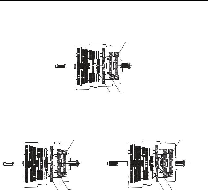
Power Flow
Front Section Power Flow - Reverse Gear
Torque will flow from the countershafts to the reverse idler gears. Torque will then flow from the reverse idler gears to the mainshaft reverse gear. Torque will now travel through the mainshaft reverse gear, the sliding clutch in the reverse position and then to the mainshaft and auxiliary drive gear. See Figure 2-6, 2-7, 2-8.
Deep Reduction
Sliding Clutch Rearward
|
|
|
|
|
|
|
|
|
|
|
|
|
|
|
|
|
|
|
|
|
|
|
|
|
|
|
|
|
|
|
|
|
|
|
|
|
|
|
|
|
|
|
|
|
|
|
|
|
|
|
|
|
|
|
|
|
|
|
|
|
|
|
|
|
|
|
|
|
|
|
|
|
|
|
|
|
|
|
|
|
|
|
|
|
|
|
|
|
|
|
|
|
|
|
|
|
|
|
|
|
|
|
|
|
|
|
|
|
|
|
|
|
|
|
|
|
|
|
|
|
|
|
|
|
|
|
|
|
|
|
|
|
|
|
|
|
|
|
|
|
|
|
|
|
|
|
|
|
|
|
|
|
|
|
|
|
|
|
|
|
|
|
|
|
|
|
|
|
|
|
|
|
|
|
|
|
|
|
|
|
|
|
|
|
|
|
|
|
|
|
|
|
|
|
|
|
|
|
|
|
|
|
|
|
|
|
|
|
|
|
|
|
|
|
|
|
|
|
|
|
|
|
|
|
|
|
|
|
|
|
|
|
|
|
|
|
|
|
|
|
|
|
|
|
|
|
|
|
|
|
|
|
|
|
|
|
|
|
|
|
|
|
|
|
|
|
|
|
|
|
|
|
|
|
|
|
|
|
|
|
|
|
|
|
|
|
|
|
|
|
|
|
|
|
|
|
|
|
|
|
|
|
|
|
|
|
|
|
|
|
|
|
|
|
|
|
|
|
|
|
|
|
|
|
|
|
|
|
|
|
|
|
|
|
|
|
|
|
|
|
|
|
|
|
|
|
|
|
|
|
|
|
|
|
|
|
|
|
|
|
|
|
|
|
|
|
|
|
|
|
|
|
|
|
|
|
|
|
|
|
|
|
|
|
|
|
|
|
|
|
|
|
|
|
|
|
|
|
|
|
|
|
|
|
|
|
|
|
|
|
|
|
|
|
|
|
|
|
|
|
|
|
|
|
|
|
|
|
Sliding Clutch Rearward |
|
|
|
|
|
Range Sliding Clutch Rearward |
||||||||||||||
Figure 2-6. Reverse Gear-Deep Reduction
Deep Reduction |
Deep Reduction |
Sliding Clutch Forward |
Sliding Clutch Forward |
|
|
|
|
|
|
|
|
|
|
|
|
|
|
|
|
|
|
|
|
|
|
|
|
|
|
|
|
|
|
|
|
|
|
|
|
|
|
|
|
|
|
|
|
|
|
|
|
|
|
|
|
|
|
|
|
|
|
|
|
|
|
|
|
|
|
|
|
|
|
|
|
|
|
|
|
|
|
|
|
|
|
|
|
|
|
|
|
|
|
|
|
|
|
|
|
|
|
|
|
|
|
|
|
|
|
|
|
|
|
|
|
|
|
|
|
|
|
|
|
|
|
|
|
|
|
|
|
|
|
|
|
|
|
|
|
|
|
|
|
|
|
|
|
|
|
|
|
|
|
|
|
|
|
|
|
|
|
|
|
|
|
|
|
|
|
|
|
|
|
|
|
|
|
|
|
|
|
|
|
|
|
|
|
|
|
|
|
|
|
|
|
|
|
|
|
|
|
|
|
|
|
|
|
|
|
|
|
|
|
|
|
|
|
|
|
|
|
|
|
|
|
|
|
|
|
|
|
|
|
|
|
|
|
|
|
|
|
|
|
|
|
|
|
|
|
|
|
|
|
|
|
|
|
|
|
|
|
|
|
|
|
|
|
|
|
|
|
|
|
|
|
|
|
|
|
|
|
|
|
|
|
|
|
|
|
|
|
|
|
|
|
|
|
|
|
|
|
|
|
|
|
|
|
|
|
|
|
|
|
|
|
|
|
|
|
|
|
|
|
|
|
|
|
|
|
|
|
|
|
|
|
|
|
|
|
|
|
|
|
|
|
|
|
|
|
|
|
|
|
|
|
|
|
|
|
|
|
|
|
|
|
|
|
|
|
|
|
|
|
|
|
|
|
|
|
|
|
|
|
|
|
|
|
|
|
|
|
|
|
|
|
|
|
|
|
|
|
|
|
|
|
|
|
|
|
|
|
|
|
|
|
|
|
|
|
|
|
|
|
|
|
|
|
|
|
|
|
|
|
|
|
|
|
|
|
|
|
|
|
|
|
|
|
|
|
|
|
|
|
|
|
|
|
|
|
|
|
|
|
|
|
|
|
|
|
|
|
|
|
|
|
|
|
|
|
|
|
|
|
|
|
|
|
|
|
|
|
|
|
|
|
|
|
|
|
|
|
|
|
|
|
|
|
|
|
|
|
|
|
|
|
|
|
|
|
|
|
|
|
|
|
|
|
|
|
|
|
|
|
|
|
|
|
|
|
|
|
|
|
|
|
|
|
|
|
|
|
|
|
|
|
|
|
|
|
|
|
|
|
|
|
|
|
|
|
|
|
|
|
|
|
|
|
|
|
|
|
|
|
|
|
|
|
|
|
|
|
|
|
|
|
|
|
|
|
|
|
|
|
|
|
|
|
|
|
|
|
|
|
|
|
|
|
|
|
|
|
|
|
|
|
|
|
|
|
|
|
|
|
|
|
|
|
|
|
|
|
|
|
|
|
|
|
|
|
|
|
|
|
|
|
|
|
|
|
|
Sliding Clutch Rearward |
|
|
|
|
|
|
|
|
|
Range Sliding Clutch Rearward |
|
|
|
|
|
|
|
|
|
|
|
|
|
Sliding Clutch Rearward |
|
|
|
|
|
|
|
Range Sliding Clutch Forward |
||||||||||||||||||||||||||||||||||||||||||||||
|
|
|
|
|
Figure 2-7. Reverse Gear-Low Range |
|
|
|
|
Figure 2-8. Reverse Gear-High Range |
|||||||||||||||||||||||||||||||||||||||||||||||||||||||||||||||||||||||||||||||||
24
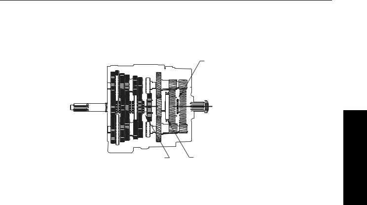
Power Flow
Auxiliary Section Power FlowLow Range
The auxiliary drive gear transfers torque to both auxiliary countershafts. If the auxiliary section is in low range, the range sliding clutch is rearward and engaged into the auxiliary mainshaft reduction gear. Torque will flow from the auxiliary countershafts, into the auxiliary mainshaft reduction gear, through the range sliding clutch and then into the output shaft (auxiliary mainshaft).
Deep Reduction
Sliding Clutch Forward
|
|
|
|
|
|
|
|
|
|
|
|
|
|
|
|
|
|
|
|
|
|
|
|
|
|
|
|
|
|
|
|
|
|
|
|
|
|
|
|
|
|
|
|
|
|
|
|
|
|
|
|
|
|
|
|
|
|
|
|
|
|
|
|
|
|
|
|
|
|
|
|
|
|
|
|
|
|
|
|
|
|
|
|
|
|
|
|
|
|
|
|
|
|
|
|
|
|
|
|
|
|
|
|
|
|
|
|
|
|
|
|
|
|
|
|
|
|
|
|
|
|
|
|
|
|
|
|
|
|
|
|
|
|
|
|
|
|
|
|
|
|
|
|
|
|
|
|
|
|
|
|
|
|
|
|
|
|
|
|
|
|
|
|
|
|
|
|
|
|
|
|
|
|
|
|
|
|
|
|
|
|
|
|
|
|
|
|
|
|
|
|
|
|
|
|
|
|
|
|
|
|
|
|
|
|
|
|
|
|
|
|
|
|
|
|
|
|
|
|
|
|
|
|
|
|
|
|
|
|
|
|
|
|
|
|
|
|
|
|
|
Range Sliding Clutch Rearward |
||
|
|
|
|
|
|
|
|
|
|
|
|
|
|
|
|
|
|
|
|
|
|
|
|
|
|
|
|
|
|
|
|
|
|
|
|
|
|
|
|
|
|
|
|
|
|
|
|
|
|
|
|
|
|
|
|
|
|
|||
|
|
|
|
|
|
|
|
|
|
|
|
|
|
|
|
|
|
|
|
|
|
|
|
|
|
|
|
|
|
|
|
|
|
|
|
|
|
|
|
|
|
|
|
|
|
|
|
|
|
|
|
|
|
|
|
|
|
|||
|
|
|
|
|
|
|
|
|
|
|
|
|
|
|
|
|
|
|
|
|
|
|
|
|
|
|
|
|
|
|
|
|
|
|
|
|
|
|
|
|
|
|
|
|
|
|
|
|
|
|
|
|
|
|
|
|
|
|||
|
|
|
|
|
|
|
|
|
|
|
|
|
|
|
|
|
|
|
|
|
|
|
|
|
|
|
|
|
|
|
|
|
|
|
|
|
|
|
|
|
|
|
|
|
|
|
|
|
|
|
|
|
|
|
|
|
|
|||
|
|
|
|
|
|
|
|
|
|
|
|
|
|
|
|
|
|
|
|
|
|
|
|
|
|
|
|
|
|
|
|
|
|
|
|
|
|
|
|
|
|
|
|
|
|
|
|
|
|
|
|
|
|
|
|
|
|
|||
|
|
|
|
|
|
|
|
|
|
|
|
|
|
|
|
|
|
|
|
|
|
|
|
|
|
|
|
|
|
|
|
|
|
|
|
|
|
|
|
|
|
|
|
|
|
|
|
|
|
|
|
|
|
|
|
|
|
|||
|
|
|
|
|
|
|
|
|
|
|
|
|
|
|
|
|
|
|
|
|
|
|
|
|
|
|
|
|
|
|
|
|
|
|
|
|
|
|
|
|
|
|
|
|
|
|
|
|
|
|
|
|
|
|
|
|
|
|||
|
|
|
|
|
|
|
|
|
|
|
|
|
|
|
|
|
|
|
|
|
|
|
|
|
|
|
|
|
|
|
|
|
|
|
|
|
|
|
|
|
|
|
|
|
|
|
|
|
|
|
|
|
|
|
|
|
|
|||
|
|
|
|
|
|
|
|
|
|
|
|
|
|
|
|
|
|
|
|
|
|
|
|
|
|
|
|
|
|
|
|
|
|
|
|
|
|
|
|
|
|
|
|
|
|
|
|
|
|
|
|
|
|
|
|
|
|
|||
|
|
|
|
|
|
|
|
|
|
|
|
|
|
|
|
|
|
|
|
|
|
|
|
|
|
|
|
|
|
|
|
|
|
|
|
|
|
|
|
|
|
|
|
|
|
|
|
|
|
|
|
|
|
|
|
|
|
|||
|
|
|
|
|
|
|
|
|
|
|
|
|
|
|
|
|
|
|
|
|
|
|
|
|
|
|
|
|
|
|
|
|
|
|
|
|
|
|
|
|
|
|
|
|
|
|
|
|
|
|
|
|
|
|
|
|
|
|||
|
|
|
|
|
|
|
|
|
|
|
|
|
|
|
|
|
|
|
|
|
|
|
|
|
|
|
|
|
|
|
|
|
|
|
|
|
|
|
|
|
|
|
|
|
|
|
|
|
|
|
|
|
|
|
|
|
|
|||
|
|
|
|
|
|
|
|
|
|
|
|
|
|
|
|
|
|
|
|
|
|
|
|
|
|
|
|
|
|
|
|
|
|
|
|
|
|
|
|
|
|
|
|
|
|
|
|
|
|
|
|
|
|
|
|
|
|
|||
|
|
|
|
|
|
|
|
|
|
|
|
|
|
|
|
|
Sliding Clutch Forward |
|
|
|
|
|
|
|
|
|
|
|
|
|
|
|
|
|||||||||||||||||||||||||||
Figure 2-9. Low Range Selected (Range Sliding Clutch Rearward)
<![endif]>Information General
25
Loading...