


SVX9000 AF Drives
User Manual
Supersedes October 2003
April 2004
MN04003002E |
For more information visit: www.eatonelectrical.com |

SVX9000 AF Drive User Manual
April 2004
Important Notice – Please Read
The product discussed in this literature is subject to terms and conditions outlined in Eaton Electrical Inc. selling policies. The sole source governing the rights and remedies of any purchaser of this equipment is the relevant Eaton Electrical Inc. selling policy.
NO WARRANTIES, EXPRESS OR IMPLIED, INCLUDING WARRANTIES OF FITNESS FOR A PARTICULAR PURPOSE OR MERCHANTABILITY, OR WARRANTIES ARISING FROM COURSE OF DEALING OR USAGE OF TRADE, ARE MADE REGARDING THE INFORMATION, RECOMMENDATIONS AND DESCRIPTIONS CONTAINED HEREIN. In no event will Eaton Electrical Inc. be responsible to the purchaser or user in contract, in tort (including negligence), strict liability or otherwise for any special, indirect, incidental or consequential damage or loss whatsoever, including but not limited to damage or loss of use of equipment, plant or power system, cost of capital, loss of power, additional expenses in the use of existing power facilities, or claims against the purchaser or user by its customers resulting from the use of the information, recommendations and descriptions contained herein.
The information contained in this manual is subject to change without notice.
Cover Photo: Cutler-Hammer® SVX9000 AF Drives.
MN04003002E |
For more information visit: www.eatonelectrical.com |
i |

SVX9000 AF Drive User Manual
|
|
|
April 2004 |
|
|
Contents |
|
|
|
|
|
Table of |
|
||
|
LIST OF FIGURES . . . . . . . . . . . . . . . . . . . . . . . . . . . . . . . . . . . . . . . . . . . . . . . . . . . . . . . . . |
iii |
|
|
LIST OF TABLES . . . . . . . . . . . . . . . . . . . . . . . . . . . . . . . . . . . . . . . . . . . . . . . . . . . . . . . . . . |
iv |
|
|
SAFETY . . . . . . . . . . . . . . . . . . . . . . . . . . . . . . . . . . . . . . . . . . . . . . . . . . . . . . . . . . . . . . . . . |
v |
|
|
|
Definitions and Symbols . . . . . . . . . . . . . . . . . . . . . . . . . . . . . . . . . . . . . . . . . . . . . . . |
v |
|
|
Hazardous High Voltage . . . . . . . . . . . . . . . . . . . . . . . . . . . . . . . . . . . . . . . . . . . . . . . |
v |
|
|
Warnings and Cautions . . . . . . . . . . . . . . . . . . . . . . . . . . . . . . . . . . . . . . . . . . . . . . . . |
vi |
|
CHAPTER 1 — OVERVIEW . . . . . . . . . . . . . . . . . . . . . . . . . . . . . . . . . . . . . . . . . . . . . . . . . |
1-1 |
|
|
|
How to Use This Manual . . . . . . . . . . . . . . . . . . . . . . . . . . . . . . . . . . . . . . . . . . . . . . . |
1-1 |
|
|
Receiving and Inspection. . . . . . . . . . . . . . . . . . . . . . . . . . . . . . . . . . . . . . . . . . . . . . . |
1-1 |
|
|
Open SVX9000 Catalog Numbers. . . . . . . . . . . . . . . . . . . . . . . . . . . . . . . . . . . . . . . . |
1-2 |
|
CHAPTER 2 — MOUNTING . . . . . . . . . . . . . . . . . . . . . . . . . . . . . . . . . . . . . . . . . . . . . . . . . |
2-1 |
|
|
|
Space Requirements . . . . . . . . . . . . . . . . . . . . . . . . . . . . . . . . . . . . . . . . . . . . . . . . . . |
2-1 |
|
|
Environmental Requirements . . . . . . . . . . . . . . . . . . . . . . . . . . . . . . . . . . . . . . . . . . . |
2-2 |
|
|
Standard Mounting Instructions . . . . . . . . . . . . . . . . . . . . . . . . . . . . . . . . . . . . . . . . . |
2-2 |
|
CHAPTER 3 — POWER WIRING . . . . . . . . . . . . . . . . . . . . . . . . . . . . . . . . . . . . . . . . . . . . . |
3-1 |
|
|
|
Guidelines . . . . . . . . . . . . . . . . . . . . . . . . . . . . . . . . . . . . . . . . . . . . . . . . . . . . . . . . . . . |
3-1 |
|
|
UL Compatible Cable Selection and Installation . . . . . . . . . . . . . . . . . . . . . . . . . . . . |
3-2 |
|
|
Installation Instructions . . . . . . . . . . . . . . . . . . . . . . . . . . . . . . . . . . . . . . . . . . . . . . . . |
3-4 |
|
|
Standard Wiring Diagrams and Terminal Locations . . . . . . . . . . . . . . . . . . . . . . . . . |
3-7 |
|
|
Power and Motor Wiring Terminal Photos. . . . . . . . . . . . . . . . . . . . . . . . . . . . . . . . . |
3-10 |
|
|
Checking the Cable and Motor Insulation . . . . . . . . . . . . . . . . . . . . . . . . . . . . . . . . . |
3-16 |
|
CHAPTER 4 — CONTROL WIRING . . . . . . . . . . . . . . . . . . . . . . . . . . . . . . . . . . . . . . . . . . . |
4-1 |
|
|
|
General Information. . . . . . . . . . . . . . . . . . . . . . . . . . . . . . . . . . . . . . . . . . . . . . . . . . . |
4-1 |
|
|
Control Wiring Details . . . . . . . . . . . . . . . . . . . . . . . . . . . . . . . . . . . . . . . . . . . . . . . . . |
4-3 |
|
CHAPTER 5 — MENU INFORMATION . . . . . . . . . . . . . . . . . . . . . . . . . . . . . . . . . . . . . . . . |
5-1 |
|
|
|
Keypad Operation . . . . . . . . . . . . . . . . . . . . . . . . . . . . . . . . . . . . . . . . . . . . . . . . . . . . |
5-1 |
|
|
Menu Navigation . . . . . . . . . . . . . . . . . . . . . . . . . . . . . . . . . . . . . . . . . . . . . . . . . . . . . |
5-3 |
|
CHAPTER 6 — START-UP . . . . . . . . . . . . . . . . . . . . . . . . . . . . . . . . . . . . . . . . . . . . . . . . . . |
6-1 |
|
|
|
Safety Precautions . . . . . . . . . . . . . . . . . . . . . . . . . . . . . . . . . . . . . . . . . . . . . . . . . . . . |
6-1 |
|
|
Sequence of Operation . . . . . . . . . . . . . . . . . . . . . . . . . . . . . . . . . . . . . . . . . . . . . . . . |
6-2 |
|
APPENDIX A — TECHNICAL DATA . . . . . . . . . . . . . . . . . . . . . . . . . . . . . . . . . . . . . . . . . . . |
A-1 |
|
|
|
General . . . . . . . . . . . . . . . . . . . . . . . . . . . . . . . . . . . . . . . . . . . . . . . . . . . . . . . . . . . . . |
A-1 |
|
|
Specifications . . . . . . . . . . . . . . . . . . . . . . . . . . . . . . . . . . . . . . . . . . . . . . . . . . . . . . . . |
A-2 |
|
|
Power Ratings. . . . . . . . . . . . . . . . . . . . . . . . . . . . . . . . . . . . . . . . . . . . . . . . . . . . . . . . |
A-4 |
|
|
Power Loss and Switching Frequency . . . . . . . . . . . . . . . . . . . . . . . . . . . . . . . . . . . . |
A-6 |
|
|
Dimensions . . . . . . . . . . . . . . . . . . . . . . . . . . . . . . . . . . . . . . . . . . . . . . . . . . . . . . . . . . |
A-10 |
|
|
EMC Capability . . . . . . . . . . . . . . . . . . . . . . . . . . . . . . . . . . . . . . . . . . . . . . . . . . . . . . . |
A-15 |
|
|
Declaration of Conformity . . . . . . . . . . . . . . . . . . . . . . . . . . . . . . . . . . . . . . . . . . . . . . |
A-15 |
|
|
Warranty and Liability Information. . . . . . . . . . . . . . . . . . . . . . . . . . . . . . . . . . . . . . . |
A-16 |
|
APPENDIX B — FAULT AND WARNING CODES . . . . . . . . . . . . . . . . . . . . . . . . . . . . . . . . |
B-1 |
|
ii |
For more information visit: www.eatonelectrical.com |
MN04003002E |

SVX9000 AF Drive User Manual
April 2004
List of Figures
Figure 2-1: Mounting Space Requirements. . . . . . . . . . . . . . . . . . . . . . . . . . . . . . . . . . . . . |
2-1 |
Figure 3-1: Input Power and Motor Cable Stripping and Wire Lengths . . . . . . . . . . . . . . |
3-4 |
Figure 3-2: Wiring Plate . . . . . . . . . . . . . . . . . . . . . . . . . . . . . . . . . . . . . . . . . . . . . . . . . . . . |
3-5 |
Figure 3-3: Ground Terminal Locations . . . . . . . . . . . . . . . . . . . . . . . . . . . . . . . . . . . . . . . . |
3-5 |
Figure 3-4: Cable Protection Plate . . . . . . . . . . . . . . . . . . . . . . . . . . . . . . . . . . . . . . . . . . . . |
3-6 |
Figure 3-5: Principle Wiring Diagram of SVX Power Unit, |
|
FR4 to FR5 and FR6 (690V) . . . . . . . . . . . . . . . . . . . . . . . . . . . . . . . . . . . . . . . . . . . . . . . |
3-7 |
Figure 3-6: Principle Wiring Diagram of SVX Power Unit, |
|
FR6 (500V), FR7 and FR8 . . . . . . . . . . . . . . . . . . . . . . . . . . . . . . . . . . . . . . . . . . . . . . . . |
3-8 |
Figure 3-7: Principle Wiring Diagram of SVX Power Unit, FR9 to FR10 . . . . . . . . . . . . . . |
3-9 |
Figure 3-8: FR4 Power and Motor Wiring Terminals . . . . . . . . . . . . . . . . . . . . . . . . . . . . . |
3-10 |
Figure 3-9: FR5 Power and Motor Wiring Terminals . . . . . . . . . . . . . . . . . . . . . . . . . . . . . |
3-11 |
Figure 3-10: FR6 Power and Motor Wiring Terminals . . . . . . . . . . . . . . . . . . . . . . . . . . . . |
3-12 |
Figure 3-11: FR7 Power and Motor Wiring Terminals . . . . . . . . . . . . . . . . . . . . . . . . . . . . |
3-13 |
Figure 3-12: FR8 Power and Motor Wiring Terminals . . . . . . . . . . . . . . . . . . . . . . . . . . . . |
3-14 |
Figure 3-13: FR9 Power and Motor Wiring Terminals . . . . . . . . . . . . . . . . . . . . . . . . . . . . |
3-15 |
Figure 4-1: Option Board Slots . . . . . . . . . . . . . . . . . . . . . . . . . . . . . . . . . . . . . . . . . . . . . . . |
4-1 |
Figure 4-2: Option Board A9 Wiring Diagram . . . . . . . . . . . . . . . . . . . . . . . . . . . . . . . . . . . |
4-3 |
Figure 4-3: Option Board A9 Jumper Location and Settings . . . . . . . . . . . . . . . . . . . . . . |
4-5 |
Figure 4-4: Option Board A2 Wiring Diagram . . . . . . . . . . . . . . . . . . . . . . . . . . . . . . . . . . . |
4-5 |
Figure 4-5: Option Board A2 Terminal Locations . . . . . . . . . . . . . . . . . . . . . . . . . . . . . . . . |
4-6 |
Figure 4-6: Positive/Negative Logic . . . . . . . . . . . . . . . . . . . . . . . . . . . . . . . . . . . . . . . . . . . |
4-6 |
Figure 5-1: Keypad and Display . . . . . . . . . . . . . . . . . . . . . . . . . . . . . . . . . . . . . . . . . . . . . . |
5-1 |
Figure 5-2: Main Menu Navigation . . . . . . . . . . . . . . . . . . . . . . . . . . . . . . . . . . . . . . . . . . . |
5-4 |
Figure 5-3: Parameter Menu Structure Example . . . . . . . . . . . . . . . . . . . . . . . . . . . . . . . . |
5-5 |
Figure 5-4: Keypad Control Menu . . . . . . . . . . . . . . . . . . . . . . . . . . . . . . . . . . . . . . . . . . . . |
5-6 |
Figure 5-5: Active Fault Display Example . . . . . . . . . . . . . . . . . . . . . . . . . . . . . . . . . . . . . . |
5-7 |
Figure 5-6: Sample Fault History Display . . . . . . . . . . . . . . . . . . . . . . . . . . . . . . . . . . . . . . |
5-9 |
Figure 5-7: System Menu Structure . . . . . . . . . . . . . . . . . . . . . . . . . . . . . . . . . . . . . . . . . . . |
5-10 |
Figure 5-8: Expander Board Menu Structure . . . . . . . . . . . . . . . . . . . . . . . . . . . . . . . . . . . |
5-18 |
Figure 5-9: Digital Inputs — DIN1, DIN2, DIN3 Status . . . . . . . . . . . . . . . . . . . . . . . . . . . . |
5-19 |
Figure 5-10: Digital Inputs — DIN4, DIN5, DIN6 Status . . . . . . . . . . . . . . . . . . . . . . . . . . . |
5-19 |
Figure 5-11: Digital and Relay Outputs — DO1, RO1, RO2 Status . . . . . . . . . . . . . . . . . . |
5-19 |
Figure 5-12: Operate Menu Navigation . . . . . . . . . . . . . . . . . . . . . . . . . . . . . . . . . . . . . . . . |
5-21 |
Figure A-1: SVX9000 Block Diagram . . . . . . . . . . . . . . . . . . . . . . . . . . . . . . . . . . . . . . . . . . |
A-2 |
Figure A-2: Power Loss as Function of Switching Frequency — |
|
3/4 – 3 hp 230V, 1 – 5 hp 480V . . . . . . . . . . . . . . . . . . . . . . . . . . . . . . . . . . . . . . . . . . . . |
A-6 |
Figure A-3: Power Loss as Function of Switching Frequency — |
|
5 – 7-1/2 hp 230V, 7-1/2 – 15 hp 480V . . . . . . . . . . . . . . . . . . . . . . . . . . . . . . . . . . . . . . |
A-7 |
Figure A-4: Power Loss as Function of Switching Frequency — |
|
10 – 15 hp 230V, 20 – 30 hp 480V . . . . . . . . . . . . . . . . . . . . . . . . . . . . . . . . . . . . . . . . . . |
A-7 |
Figure A-5: Power Loss as Function of Switching Frequency — |
|
20 – 30 hp 230V, 40 – 60 hp 480V . . . . . . . . . . . . . . . . . . . . . . . . . . . . . . . . . . . . . . . . . . |
A-8 |
Figure A-6: Power Loss as Function of Switching Frequency — |
|
75 – 125 hp 480V . . . . . . . . . . . . . . . . . . . . . . . . . . . . . . . . . . . . . . . . . . . . . . . . . . . . . . . |
A-8 |
Figure A-7: Power Loss as Function of Switching Frequency — |
|
150 – 200 hp 480V . . . . . . . . . . . . . . . . . . . . . . . . . . . . . . . . . . . . . . . . . . . . . . . . . . . . . . |
A-9 |
MN04003002E |
For more information visit: www.eatonelectrical.com |
iii |

SVX9000 AF Drive User Manual
|
April 2004 |
List of Figures, continued |
|
Figure A-8: NEMA Type 1 Enclosure Dimensions . . . . . . . . . . . . . . . . . . . . . . . . . . . . . . . |
A-10 |
Figure A-9: NEMA 1 and NEMA 12 with Flange Kit, FR4, |
|
FR5 and FR6 Enclosure Dimensions . . . . . . . . . . . . . . . . . . . . . . . . . . . . . . . . . . . . . . |
A-11 |
Figure A-10: NEMA 1 with Flange Kit, FR7 and FR8 Enclosure Dimensions . . . . . . . . . . |
A-12 |
Figure A-11: FR9 Enclosure Dimensions . . . . . . . . . . . . . . . . . . . . . . . . . . . . . . . . . . . . . . |
A-13 |
Figure A-12: FR9 with Flange Kit Enclosure Dimensions . . . . . . . . . . . . . . . . . . . . . . . . . |
A-14 |
List of Tables |
|
Table 1-1: SVX9000 AF Drive Catalog Numbering System . . . . . . . . . . . . . . . . . . . . . . . . |
1-2 |
Table 2-1: Space Requirements for Mounting a SVX9000 Drive. . . . . . . . . . . . . . . . . . . . |
2-1 |
Table 2-2: Cooling Airflow Requirements . . . . . . . . . . . . . . . . . . . . . . . . . . . . . . . . . . . . . . |
2-2 |
Table 3-1: Cable Spacings . . . . . . . . . . . . . . . . . . . . . . . . . . . . . . . . . . . . . . . . . . . . . . . . . . |
3-1 |
Table 3-2: Cable and Fuse Sizes – 230V Ratings. . . . . . . . . . . . . . . . . . . . . . . . . . . . . . . . . |
3-2 |
Table 3-3: Cable and Fuse Sizes – 480V Ratings. . . . . . . . . . . . . . . . . . . . . . . . . . . . . . . . . |
3-2 |
Table 3-4: Cable and Fuse Sizes – 575V Ratings. . . . . . . . . . . . . . . . . . . . . . . . . . . . . . . . . |
3-3 |
Table 3-5: Maximum Symmetrical Supply Current . . . . . . . . . . . . . . . . . . . . . . . . . . . . . . |
3-3 |
Table 3-6: Power Connection Tightening Torque . . . . . . . . . . . . . . . . . . . . . . . . . . . . . . . . |
3-3 |
Table 3-7: Power and Motor Cable Stripping Lengths . . . . . . . . . . . . . . . . . . . . . . . . . . . . |
3-4 |
Table 4-1: Tightening Torques of Terminals . . . . . . . . . . . . . . . . . . . . . . . . . . . . . . . . . . . . |
4-2 |
Table 4-2: Control Wiring Instructions. . . . . . . . . . . . . . . . . . . . . . . . . . . . . . . . . . . . . . . . . |
4-2 |
Table 4-3: Option Board A9 Terminal Descriptions . . . . . . . . . . . . . . . . . . . . . . . . . . . . . . |
4-4 |
Table 4-4: Option Board A2 Terminal Descriptions . . . . . . . . . . . . . . . . . . . . . . . . . . . . . . |
4-6 |
Table 5-1: LCD Status Indicators . . . . . . . . . . . . . . . . . . . . . . . . . . . . . . . . . . . . . . . . . . . . . |
5-1 |
Table 5-2: LED Status Indicators . . . . . . . . . . . . . . . . . . . . . . . . . . . . . . . . . . . . . . . . . . . . . |
5-2 |
Table 5-3: Navigation Buttons . . . . . . . . . . . . . . . . . . . . . . . . . . . . . . . . . . . . . . . . . . . . . . . |
5-2 |
Table 5-4: Fault Types . . . . . . . . . . . . . . . . . . . . . . . . . . . . . . . . . . . . . . . . . . . . . . . . . . . . . . |
5-8 |
Table 5-5: Fault Time Data . . . . . . . . . . . . . . . . . . . . . . . . . . . . . . . . . . . . . . . . . . . . . . . . . . |
5-8 |
Table 5-6: Total Counters . . . . . . . . . . . . . . . . . . . . . . . . . . . . . . . . . . . . . . . . . . . . . . . . . . . |
5-15 |
Table 5-7: Trip Counters . . . . . . . . . . . . . . . . . . . . . . . . . . . . . . . . . . . . . . . . . . . . . . . . . . . . |
5-15 |
Table 5-8: Software Information . . . . . . . . . . . . . . . . . . . . . . . . . . . . . . . . . . . . . . . . . . . . . |
5-16 |
Table 5-9: Application Information . . . . . . . . . . . . . . . . . . . . . . . . . . . . . . . . . . . . . . . . . . . |
5-16 |
Table 5-10: Hardware Information . . . . . . . . . . . . . . . . . . . . . . . . . . . . . . . . . . . . . . . . . . . . |
5-16 |
Table 5-11: Expander Board Information . . . . . . . . . . . . . . . . . . . . . . . . . . . . . . . . . . . . . . |
5-17 |
Table 5-12: Monitoring Menu Items — Standard Application Example . . . . . . . . . . . . . . |
5-19 |
Table 5-13: Operate Menu Items — Standard Application Example . . . . . . . . . . . . . . . . |
5-20 |
Table A-1: SVX9000 Drive Specifications . . . . . . . . . . . . . . . . . . . . . . . . . . . . . . . . . . . . . . |
A-2 |
Table A-2: Output Power Ratings — 230V CT . . . . . . . . . . . . . . . . . . . . . . . . . . . . . . . . . . |
A-4 |
Table A-3: Output Power Ratings — 480V CT . . . . . . . . . . . . . . . . . . . . . . . . . . . . . . . . . . |
A-5 |
Table A-4: Output Power Ratings — 575V CT . . . . . . . . . . . . . . . . . . . . . . . . . . . . . . . . . . |
A-5 |
Table A-5: NEMA Type 1/Type 12 Enclosure Dimensions . . . . . . . . . . . . . . . . . . . . . . . . . |
A-10 |
Table A-6: FR4, FR5 and FR6 with Flange Kit Enclosure Dimensions . . . . . . . . . . . . . . . . |
A-11 |
Table A-7: FR7 and FR8 with Flange Kit Enclosure Dimensions . . . . . . . . . . . . . . . . . . . . |
A-12 |
Table A-8: FR9 Enclosure Dimensions. . . . . . . . . . . . . . . . . . . . . . . . . . . . . . . . . . . . . . . . . |
A-13 |
Table A-9: FR9 with Flange Kit Enclosure Dimensions . . . . . . . . . . . . . . . . . . . . . . . . . . . |
A-14 |
Table B-1: Fault Codes . . . . . . . . . . . . . . . . . . . . . . . . . . . . . . . . . . . . . . . . . . . . . . . . . . . . . |
B-1 |
iv |
For more information visit: www.eatonelectrical.com |
MN04003002E |
SVX9000 AF Drive User Manual
April 2004
Safety
Definitions and Symbols
WARNING
This symbol indicates high voltage. It calls your attention to items or operations that could be dangerous to you and other persons operating this equipment. Read the message and follow the instructions carefully.
This symbol is the “Safety Alert Symbol.” It occurs with either of two signal words: CAUTION or WARNING, as described below.
WARNING
Indicates a potentially hazardous situation which, if not avoided, can result in serious injury or death.
CAUTION
Indicates a potentially hazardous situation which, if not avoided, can result in minor to moderate injury, or serious damage to the equipment. The situation described in the CAUTION may, if not avoided, lead to serious results. Important safety measures are described in CAUTION (as well as WARNING).
Hazardous High Voltage
WARNING
Motor control equipment and electronic controllers are connected to hazardous line voltages. When servicing drives and electronic controllers, there may be exposed components with housings or protrusions at or above line potential. Extreme care should be taken to protect against shock.
•Stand on an insulating pad and make it a habit to use only one hand when checking components.
•Always work with another person in case an emergency occurs.
•Disconnect power before checking controllers or performing maintenance.
•Be sure equipment is properly grounded.
•Wear safety glasses whenever working on electronic controllers or rotating machinery.
MN04003002E |
For more information visit: www.eatonelectrical.com |
v |
SVX9000 AF Drive User Manual
April 2004
Warnings and Cautions
Read this manual thoroughly and make sure you understand the procedures before you attempt to install, set up, or operate this Cutler-Hammer® SVX9000 Adjustable Frequency Drive from Eaton Electrical®.
Warnings
WARNING
Be sure to ground the unit following the instructions in this manual.
Ungrounded units may cause electric shock and/or fire.
WARNING
This equipment should be installed, adjusted, and serviced by qualified electrical maintenance personnel familiar with the construction and operation of this type of equipment and the hazards involved. Failure to observe this precaution could result in death or severe injury.
WARNING
Components within the SVX9000 power unit are live when the drive is connected to power. Contact with this voltage is extremely dangerous and may cause death or severe injury.
WARNING
Line terminals (L1, L2, L3), motor terminals (U, V, W) and the DClink/brake resistor terminals (-/+) are live when the drive is connected to power, even if the motor is not running. Contact with this voltage is extremely dangerous and may cause death or severe injury.
WARNING
Even though the control I/O-terminals are isolated from line voltage, the relay outputs and other I/O-terminals may have dangerous voltage present even when the drive is disconnected from power. Contact with this voltage is extremely dangerous and may cause death or severe injury.
WARNING
The SVX9000 drive has a large capacitive leakage current during operation, which can cause enclosure parts to be above ground potential. Proper grounding, as described in this manual, is required. Failure to observe this precaution could result in death or severe injury.
WARNING
Before applying power to the SVX9000 drive, make sure that the front and cable covers are closed and fastened to prevent exposure to potential electrical fault conditions. Failure to observe this precaution could result in death or severe injury.
vi |
For more information visit: www.eatonelectrical.com |
MN04003002E |
SVX9000 AF Drive User Manual
April 2004
WARNING
An upstream disconnect/protective device must be provided as required by the National Electric Code (NEC). Failure to follow this precaution may result in death or severe injury.
WARNING
Before opening the SVX9000 drive covers:
•Disconnect all power to the SVX9000 drive.
•Wait a minimum of 5 (five) minutes after all the lights on the keypad are off. This allows time for the DC bus capacitors to discharge.
•A hazard voltage may still remain in the DC bus capacitors even if the power has been turned off. Confirm that the capacitors have fully discharged by measuring their voltage using a multimeter set to measure DC voltage.
Failure to follow the above precautions may cause death or severe injury.
Cautions
CAUTION
Do not perform any meggar or voltage withstand tests on any part of the SVX9000 drive or its components. Improper testing may result in damage.
CAUTION
Prior to any tests or measurements of the motor or the motor cable, disconnect the motor cable at the SVX9000 output terminals (U, V, W) to avoid damaging the SVX9000 during motor or cable testing.
CAUTION
Do not touch any components on the circuit boards. Static voltage discharge may damage the components.
CAUTION
Any electrical or mechanical modification to this equipment without prior written consent of Eaton’s Cutler-Hammer business unit will void all warranties and may result in a safety hazard in addition and voiding of the UL listing.
CAUTION
Install the SVX9000 drive on flame-resistant material such as a steel plate to reduce the risk of fire.
CAUTION
Install the SVX9000 drive on a perpendicular surface that is able to support the weight of the drive and is not subject to vibration, to lessen the risk of the drive falling and being damaged and/or causing personal injury.
MN04003002E |
For more information visit: www.eatonelectrical.com |
vii |
SVX9000 AF Drive User Manual
April 2004
CAUTION
Prevent foreign material such as wire clippings or metal shavings from entering the drive enclosure, as this may cause arcing damage and fire.
CAUTION
Install the SVX9000 drive in a well-ventilated room that is not subject to temperature extremes, high humidity, or condensation, and avoid locations that are directly exposed to sunlight, or have high concentrations of dust, corrosive gas, explosive gas, inflammable gas, grinding fluid mist, etc. Improper installation may result in a fire hazard.
Motor and Equipment Safety
CAUTION
Before starting the motor, check that the motor is mounted properly and aligned with the driven equipment. Ensure that starting the motor will not cause personal injury or damage equipment connected to the motor.
CAUTION
Set the maximum motor speed (frequency) in the HXV9000 drive according to the requirements of the motor and the equipment connected to it. Incorrect maximum frequency settings can cause motor or equipment damage and personal injury.
CAUTION
Before reversing the motor rotation direction, ensure that this will not cause personal injury or equipment damage.
CAUTION
Make sure that no power correction capacitors are connected to the SVX9000 output or the motor terminals to prevent SVX9000 malfunction and potential damage.
CAUTION
Make sure that the SVX9000 output terminals (U, V, W) are not connected to the utility line power as severe damage to the SVX9000 may occur.
viii |
For more information visit: www.eatonelectrical.com |
MN04003002E |
SVX9000 AF Drive User Manual
April 2004
Chapter 1 — Overview
This chapter describes the purpose and contents of this manual, the receiving inspection recommendations and the Cutler-Hammer® SVX9000 catalog numbering system.
How to Use This Manual
The purpose of this manual is to provide you with information necessary to install, set and customize parameters, start up, troubleshoot and maintain the Cutler-Hammer SVX9000 drive by Eaton Electrical®. To provide for safe installation and operation of the equipment, read the safety guidelines at the beginning of this manual and follow the procedures outlined in the following chapters before connecting power to the SVX9000. Keep this operating manual handy and distribute to all users, technicians and maintenance personnel for reference.
Chapter 1 – Overview is the chapter you are reading now.
Chapter 2 – Mounting
Chapter 3 – Power Wiring
Chapter 4 – Control Wiring
Chapter 5 – Menu Information
Chapter 6 – Start-Up
Appendix A – Technical Data
Appendix B – Fault and Warning Codes
Receiving and Inspection
This SVX9000 AC drive has met a stringent series of factory quality requirements before shipment. It is possible that packaging or equipment damage may have occurred during shipment. After receiving your SVX9000 drive, please check for the following:
●Check to make sure that the package(s) includes the SVX9000 drive, the User Manual, and rubber conduit covers, screws, conduit plate and ground straps.
●Inspect the unit to ensure it was not damaged during shipment.
●Make sure that the part number indicated on the nameplate corresponds with the Catalog Number on your order.
If shipping damage has occurred, please contact and file a claim with the carrier involved immediately.
If the delivery does not correspond to your order, please contact your Eaton Electrical Cutler-Hammer representative.
Note: Do not destroy the packing. The template printed on the protective cardboard can be used for marking the mounting points of the SVX9000 on the wall or cabinet.
MN04003002E |
For more information visit: www.eatonelectrical.com |
1-1 |
SVX9000 AF Drive User Manual
April 2004
Open SVX9000 Catalog Numbers
Table 1-1: SVX9000 AF Drive Catalog Numbering System
S V X 0 0 7 A 1 - 4 A 1 B 1
|
|
|
|
|
|
|
|
|
|
|
|
|
|
|
|
|
|
|
|
|
|
|
|
|
|
|
|
|
|
|
|
|
|
|
|
|
|
|
|
|
|
|
|
|
|
Product |
|
|
|
|
|
|
|
|
|
|
|
|
|
|
|
|
|
|
|
|
|
|
|
|
|
|
|
|
|
|
|
|
|
Expansion Slots 3 through 5 |
|||||||
SVX = |
SVX Industrial Drive |
|
|
|
|
|
|
|
|
|
|
|
|
|
|
|
|
|
|
|
|
|
|
|
|
|
|
• Option boards be selected from left |
|||||||||||||||
SPX = |
SPX Drive |
|
|
|
|
|
|
|
|
|
|
|
|
|
|
|
|
|
|
|
|
|
|
|
|
|
|
|
|
|
|
|
to right, in alpha-numeric order. |
||||||||||
|
|
(Fr10 and larger only) |
|
|
|
|
|
|
|
|
|
|
|
|
|
|
|
|
|
|
|
|
|
|
|
|
|
• Characters to be left blank if no |
|||||||||||||||
|
|
|
|
|
|
|
|
|
|
|
|
|
|
|
|
|
|
|
|
|
|
|
|
|
|
|
|
|
|
|
|
|
|
|
options are selected |
||||||||
|
|
|
|
|
|
|
|
|
|
|
|
|
|
|
|
|
|
|
|
|
|
|
|
|
|
|
|
|
|
|
|
|
|
||||||||||
|
|
|
|
|
|
|
|
|
|
|
|
|
|
|
|
|
|
|
|
|
|
|
|
|
|
|
|
|
|
|
|
|
|
|
|
|
|
|
|
|
|
|
|
|
Horsepower (CT) |
|
|
|
|
|
|
|
|
|
|
|
|
|
|
|
|
|
|
|
|
|
|
|
|
|
|
|
|
|
|
|
|
|
|
||||||||
|
|
|
|
|
|
|
|
|
|
|
|
|
|
|
|
|
|
|
|
|
|
|
|
|
|
Board Modifications |
|
||||||||||||||||
F07 |
= 3/4 |
|
030 |
= 30 |
|
|
|
|
|
|
|
|
|
|
|
|
|
|
|
|
|
|
|
|
|
|
|
|
|
|
|
|
|||||||||||
|
|
|
|
|
|
|
|
|
|
|
|
|
|
|
|
|
|
|
|
|
|
|
|
|
|
1 = Standard Boards (A9, A2) |
|
||||||||||||||||
001 |
= 1 |
|
|
040 |
= 40 |
|
|
|
|
|
|
|
|
|
|
|
|
|
|
|
|
|
|
|
|
|
|
|
|
|
|
||||||||||||
F15 |
= 1-1/2 |
|
050 |
= 50 |
|
|
|
|
|
|
|
|
|
|
|
|
|
|
|
|
|
|
|
|
|
|
|
|
|
|
|
|
|
|
|
|
|
|
|
|
|||
002 |
= 2 |
|
|
060 |
= 60 |
|
|
|
|
|
|
|
|
|
|
|
|
|
|
|
|
|
|
|
|
|
|
|
|
|
|
|
|
|
|
|
|
|
|
|
|
||
003 |
= 3 |
|
|
075 |
= 75 |
|
|
|
|
|
|
|
|
|
|
|
|
|
|
|
|
|
|
|
|
|
|
|
|
|
|
|
|
|
Braking |
|
|
||||||
|
|
|
|
|
|
|
|
|
|
|
|
|
|
|
|
|
|
|
|||||||||||||||||||||||||
004 |
= 5 VT Only |
100 |
= 100 |
|
|
|
|
|
|
|
|
|
|
|
|
|
|
|
|
|
|
|
|
|
|
N = No Brake Chopper |
|
|
|||||||||||||||
005 |
= 5 |
|
|
125 |
= 125 |
|
|
|
|
|
|
|
|
|
|
|
|
|
|
|
|
|
|
|
|
|
|
B = Internal Brake Chopper |
|
|
|||||||||||||
006 |
= 7-1/2 VT Only |
150 |
= 150 |
|
|
|
|
|
|
|
|
|
|
|
|
|
|
|
|
|
|
|
|
|
|
|
|
|
|
|
|
|
|
|
|
|
|
|
|||||
|
|
|
|
|
|
|
|
|
|
|
|
|
|
|
|
|
|
|
|
|
|
|
|
|
|
|
|
|
|
||||||||||||||
007 |
= 7-1/2 |
|
200 |
= 200 |
|
|
|
|
|
|
|
|
|
|
|
|
|
|
|
|
|
|
|
|
|
|
|
|
|
|
|
|
|
|
|
|
|
|
|
||||
010 |
= 10 |
|
250 |
= 250 |
|
|
|
|
|
|
|
|
|
|
|
|
|
|
|
|
|
|
|
|
|
|
Input Options |
|
|
||||||||||||||
|
|
|
|
|
|
|
|
|
|
|
|
|
|
|
|
|
|||||||||||||||||||||||||||
015 |
= 15 |
|
300 |
= 300 |
|
|
|
|
|
|
|
|
|
|
|
|
|
|
|
|
|
|
|
|
|
|
|
|
|
|
|
|
|
|
|
|
|
|
|
||||
|
|
|
|
|
|
|
|
|
|
|
|
|
|
1 = 3-Phase, EMC H |
|
|
|
||||||||||||||||||||||||||
020 |
= 20 |
|
350 |
= 350 |
|
|
|
|
|
|
|
|
|
|
|
|
|
|
|
|
|
|
|
|
|
||||||||||||||||||
|
|
|
|
|
|
|
|
|
|
|
|
|
|
|
|
|
|
|
|
2 = 3-Phase, EMC N |
|
|
|
||||||||||||||||||||
025 |
= 25 |
|
|
|
|
|
|
|
|
|
|
|
|
|
|
|
|
|
|
|
|
|
|
|
|
|
|
|
|||||||||||||||
|
|
|
|
|
|
|
|
|
|
|
|
|
|
|
|
|
|
|
|
|
|
|
|
|
|
|
|
|
|
|
|
|
|
|
|
|
|
|
|
|
|||
|
|
|
|
|
|
|
|
|
|
|
|
|
|
|
|
|
|
|
|
|
|
|
|
|
|
|
|
|
|
|
|
|
|
|
|
|
|
||||||
|
|
|
|
|
|
|
|
|
|
|
|
|
|
|
|
|
|
|
|
|
|
|
|
|
|
|
|
|
|
|
|
|
|||||||||||
|
|
|
|
AFD Software Series |
|
|
|
|
|
|
|
|
|
|
|
|
|
|
|
Keypad |
|
||||||||||||||||||||||
|
|
|
|
|
|
|
|
|
|
|
|
|
|
|
|
|
|
||||||||||||||||||||||||||
|
|
|
|
|
|
|
|
|
|
|
|
|
|
|
|
|
|
|
|
|
|
|
|
|
|
|
|
|
|
|
|
|
|
||||||||||
|
|
|
|
|
|
|
|
|
|
|
|
|
|
|
|
|
|
|
|
|
|
|
|
A = AlphaNumeric |
|
|
|
|
|
|
|||||||||||||
|
|
|
A = Standard Software |
|
|
|
|
|
|
|
|
|
|
|
|
|
|
|
|
||||||||||||||||||||||||
|
|
|
|
|
|
|
|
|
|
|
|
|
|
|
|
|
|
|
|
|
|
|
|
|
|
|
|
|
|
|
|
|
|||||||||||
|
|
|
|
|
|
|
|
|
|
|
|
|
|
|
|
|
|
|
|
|
|
|
|
|
|
|
|||||||||||||||||
|
|
|
|
|
|
|
|
|
|
|
|
|
|
|
|
|
|
|
|
|
|
|
|
|
|
|
|
|
|
|
|
|
|
|
|
|
|
|
|
|
|
|
|
|
|
|
|
|
Enclosure |
|
|
|
|
|
|
|
|
Voltage |
|
||||||||||||||||||||||||||||
|
|
|
|
|
|
|
|
|
|
|
|
||||||||||||||||||||||||||||||||
|
|
|
|
|
|
|
|
|
|
|
|
|
|
|
|
|
|
|
|
|
|
|
|
|
|
|
|
|
|
|
|
|
|
|
|||||||||
|
|
|
|
|
|
|
|
|
|
|
|
|
|
|
|
|
|
|
2 = 208 – 230V |
|
|
|
|
|
|
|
|
|
|
|
|
||||||||||||
|
|
|
|
0 = Open Chassis |
|
|
|
|
|
|
|
|
|
|
|
|
|
|
|
|
|
||||||||||||||||||||||
|
|
|
|
|
|
|
|
|
4 = 380 – 500V |
|
|
|
|
|
|
|
|
|
|
|
|
||||||||||||||||||||||
|
|
|
|
1 = NEMA Type 1 |
|
|
|
|
|
|
|||||||||||||||||||||||||||||||||
|
|
|
|
|
|
|
|
|
5 = 525 – 690V |
|
|
|
|
|
|
|
|
|
|
|
|
||||||||||||||||||||||
|
|
|
|
2 = NEMA Type 12 |
|
|
|
|
|
|
|||||||||||||||||||||||||||||||||
|
|
|
|
|
|
|
|
|
|
|
|
|
|
|
|
|
|
|
|
|
|
|
|
|
|
|
|
|
|
|
|
|
|
||||||||||
|
|
|
|
|
|
|
|
|
|
|
|
|
|
|
|
|
|
|
|
|
|
|
|
|
|
|
|
|
|
|
|
|
|
|
|
|
|
|
|
|
|
|
|
All 230V Drives and 480V Drives up to 200 hp (CT) are only available with Input Option 1.480V Drives 250 hp (CT) or larger are only available with Input Option 2.
480V Drives up to 30 hp (CT) are only available with Brake Chopper Option B.
480V Drives 40 hp (CT) and larger come with Brake Chopper Option N as standard.230V Drives up to 15 hp (CT) are only available with Brake Chopper Option B.
230V Drives 20 hp (CT) or larger come with Brake Chopper Option N as standard.
480V Drives 250 hp, 300 hp and 350 hp (CT) are only available with Enclosure Style 0 (Chassis).
1-2 |
For more information visit: www.eatonelectrical.com |
MN04003002E |
SVX9000 AF Drive User Manual
April 2004
Chapter 2 — Mounting
The SVX9000 drive may be mounted side-by-side or stacked vertically, as outlined in the following section.
Space Requirements
To ensure proper air circulation and cooling, follow the guidelines below.
Table 2-1: Space Requirements for Mounting a SVX9000 Drive
|
|
|
|
|
Dimensions in Inches (mm) |
|
|
|||
Frame |
Drive Type |
A |
A2 |
B |
C |
D |
|
|||
|
|
|
|
|
|
|
|
|
||
4 |
230V, 1 |
– 3 hp VT, 3/4 – 3 hp CT |
0.8 |
— |
0.8 |
3.9 (100) |
2.0 |
|
||
|
480V, 1 |
– 5 hp CT, 1-1/2 – 7-1/2 hp VT |
(20) |
|
(20) |
|
(50) |
|||
5 |
230V, 5 |
– 10 hp VT, 5 – 7-1/2 hp CT |
1.2 |
— |
0.8 |
4.7 (120) |
2.4 |
|
||
|
480V, 7-1/2 – 15 hp CT, 10 – 20 hp VT |
(30) |
|
(20) |
|
(60) |
||||
|
|
|
|
|
|
|
|
|
||
6 |
230V, 15 – |
20 hp VT, 10 – 15 hp CT |
1.2 |
— |
0.8 |
6.3 (160) |
3.1 |
|
||
|
480V, 20 – |
30 hp CT, 25 – 40 hp VT |
(30) |
|
(20) |
|
(80) |
|||
|
575V, 2 |
– 25 hp CT, 3 – 30 hp VT |
|
|
|
|
|
|
||
|
|
|
|
|
|
|
|
|
||
7 |
230V, 25 – |
40 hp VT, 20 – 30 hp CT |
3.1 |
— |
3.1 |
11.8 |
3.9 |
(100) |
||
|
480V, 40 |
– |
60 hp CT, 50 – 75 hp VT |
(80) |
|
(80) |
(300) |
|
|
|
|
575V, 30 |
– |
40 hp CT, 40 – 50 hp VT |
|
|
|
|
|
|
|
|
|
|
|
|
|
|
|
|
|
|
8 |
480V, 75 |
– |
125 hp CT, 100 – 150 hp VT |
3.1 |
5.9 (150) |
3.1 |
11.8 |
7.9 |
(200) |
|
|
575V, 50 |
– |
75 hp CT, 60 – 100 hp VT |
(80) |
|
(80) |
(300) |
|
|
|
|
|
|
|
|
|
|
|
|||
9 |
480V, 200 – 250 hp VT, 150 – 200 hp CT |
2.0 |
— |
3.1 |
15.7 |
9.8 |
(250) |
|||
|
575V, 100 – 150 hp CT, 150 – 200 hp VT |
(50) |
|
(80) |
(400) |
13.8 |
||||
|
|
|
|
|
|
|
|
|
(350) |
|
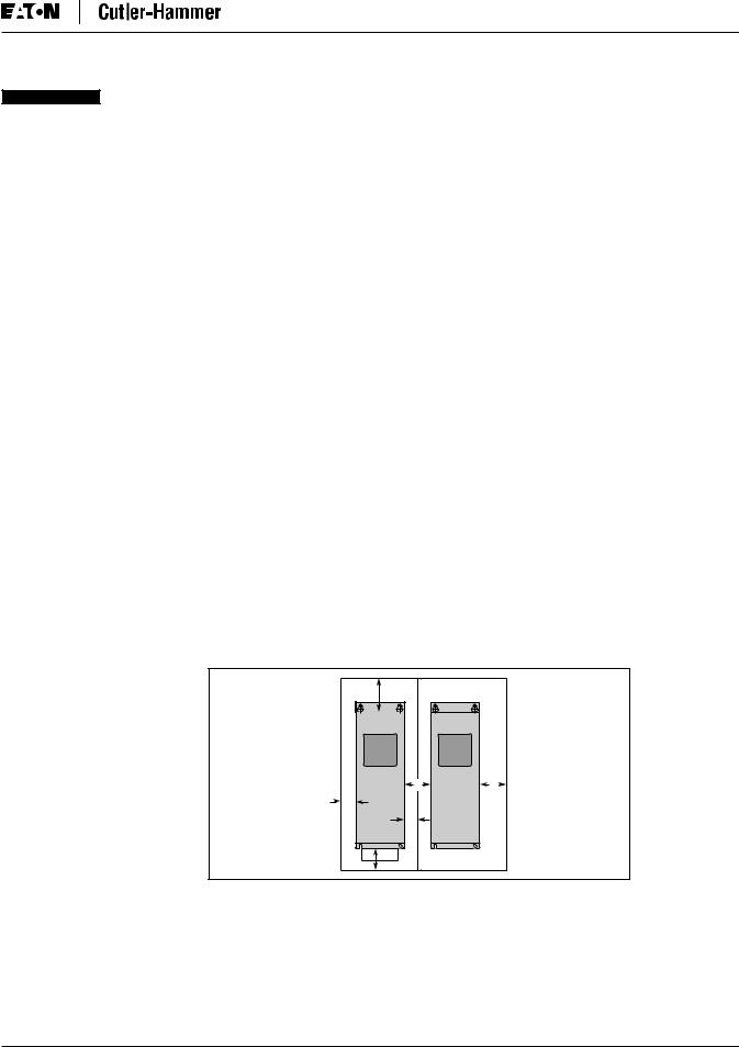
Dimensions represent the minimum clearance needed when mounting a SVX9000. See Figure 2-1 below. A = clearance around the SVX9000.
A2 = clearance needed to change the fan without disconnecting the motor cables.
B = distance between adjacent SVX9000s or between the SVX9000 and an enclosure wall. C = clearance above the SVX9000.
D = clearance below the SVX9000.
Minimum clearance below the SVX9000 needed to change the fan.
|
C |
|
|
B |
B |
A |
A |
|
A2 |
|
|
|
A2 |
|
|
D |
|
Figure 2-1: Mounting Space Requirements.
If several units are mounted above each other, the clearance between the drives should equal C + D (see Table 2-1 and Figure 2-1 above). In addition, the outlet air used for cooling the lower unit must be directed away from the inlet air used by the upper unit.
MN04003002E |
For more information visit: www.eatonelectrical.com |
2-1 |

SVX9000 AF Drive User Manual
April 2004
Environmental Requirements
Ensure that the environment meets the requirements listed in Table A-1 of Appendix A for any storage or operating situation.
Table 2-2 specifies the minimum airflow required in the area where the drive will be mounted.
Table 2-2: Cooling Airflow Requirements
Drive Type |
Cooling Air Required |
||
|
|
||
|
|
||
230V, 3/4 – 3 hp CT |
41 cfm (70 m3/h) |
||
480V, 1 – 5 hp CT |
|
||
|
|
||
230V, 5 – 7-1/2 hp CT |
112 cfm (190 m3/h) |
||
480V, 7-1/2 – 15 hp CT |
|
||
|
|
|
|
230V, 10 – |
15 hp CT |
250 cfm (425 m3/h) |
|
480V, 20 – |
30 hp CT |
|
|
575V, 2 – 25 hp CT |
|
||
|
|
|
|
230V, 20 – |
30 hp CT |
250 cfm (425 m3/h) |
|
480V, 40 |
– |
60 hp CT |
|
575V, 30 |
– |
40 hp CT |
|
|
|
|
|
480V, 75 |
– |
125 hp CT |
383 cfm (650 m3/h) |
575V, 60 |
– |
75 hp CT |
|
|
|
||
480V, 150 – 200 hp CT |
765 cfm (1300 m3/h) |
||
575V, 100 – 150 hp CT |
|
||
|
|
|
|
Standard Mounting Instructions
1.Measure the mounting space to ensure that it allows for the minimum space surrounding the drive. Drive dimensions are in Appendix A.
2.Make sure the mounting surface is flat and strong enough to support the drive, is not flammable, and is not subject to excessive motion or vibration.
3.Ensure that the minimum airflow requirements for your drive are met at the mounting location.
4.Mark the location of the mounting holes on the mounting surface, using the template provided on the cover of the cardboard shipping package.
5.Using fasteners appropriate to your drive and mounting surface, securely attach the drive to the mounting surface using all 4 screws or bolts.
2-2 |
For more information visit: www.eatonelectrical.com |
MN04003002E |

SVX9000 AF Drive User Manual
April 2004
Chapter 3 — Power Wiring
Guidelines
To ensure proper wiring, use the following guidelines:
●Use heat-resistant copper cables only, +75°C or higher.
●The input line cable and line fuses must be sized in accordance with the rated input current of the unit. See Tables 3-2 and 3-5.
●Consistent with UL listing requirements, for maximum protection of the SVX9000 drive, UL recognized fuses type RK5 should be used for 480V and 230V ratings.
●If the motor temperature sensing is used for overload protection, the output cable size may be selected based on the motor specifications.
●If three or more shielded cables are used in parallel for the output on the larger units, every cable must have its own overload protection.
●Avoid placing the motor cables in long parallel lines with other cables.
●If the motor cables run in parallel with other cables, note the minimum distances between the motor cables and other cables given in Table 3-1 below:
Table 3-1: Cable Spacings
Minimum Distance Between |
|
|
|
Cables in Feet (m) |
Cable in Feet (m) |
||
|
|
|
|
|
|
|
|
1 (0.3) |
≤ |
164 |
(50) |
|
|
|
|
3.3 (1.0) |
≤ |
656 |
(200) |
|
|
|
|
●The spacings of Table 3-1 also apply between the motor cables and signal cables of other systems.
●The maximum length of the motor cables is as follows:
–1 – 2 hp, 230V units, 328 ft. (100m)
–All other hp units, 984 ft. (300m)
●The motor cables should cross other cables at an angle of 90 degrees.
●If conduit is being used for wiring, use separate conduits for the input power wiring, the output power wiring, the signal wiring and the control wiring.
MN04003002E |
For more information visit: www.eatonelectrical.com |
3-1 |

SVX9000 AF Drive User Manual
April 2004
UL Compatible Cable Selection and Installation
Use only copper wire with temperature rating of at least 75°C.
Table 3-2: Cable and Fuse Sizes – 230V Ratings
|
Frame |
|
Fuse |
Wire Size |
|
Terminal Size |
|
hp |
Size |
I (A) |
(A) |
Power |
Ground |
Power |
Ground |
|
|
l |
|
|
|
|
|
|
|
|
|
|
|
|
|
1 |
FR4 |
4.8 |
10 |
14 |
14 |
12 – 16 |
14 – 16 |
1-1/2 |
|
6.6 |
10 |
14 |
14 |
12 – 16 |
14 – 16 |
2 |
|
7.8 |
10 |
14 |
14 |
12 – 16 |
14 – 16 |
3 |
|
11 |
15 |
12 |
14 |
12 – 16 |
14 – 16 |
|
|
|
|
|
|
|
|
5 |
FR5 |
17.5 |
20 |
10 |
10 |
8 – 16 |
8 – 16 |
7-1/2 |
|
25 |
30 |
8 |
8 |
8 – 18 |
8 – 16 |
|
|
|
|
|
|
|
|
10 |
FR6 |
31 |
40 |
8 |
8 |
0 – 14 |
2 – 10 |
15 |
|
48 |
60 |
4 |
6 |
0 – 14 |
2 – 10 |
|
|
|
|
|
|
|
|
20 |
FR7 |
61 |
80 |
2 |
6 |
0 – 14 |
00 – 10 |
25 |
|
72 |
100 |
2 |
6 |
0 – 14 |
00 – 10 |
30 |
|
87 |
110 |
1/0 |
4 |
0 – 14 |
00 – 10 |
|
|
|
|
|
|
|
|
UL recognized type RK.
Based on a maximum environment of 104°F (40°C).
Table 3-3: Cable and Fuse Sizes – 480V Ratings
|
Frame |
|
Fuse |
Wire Size |
|
Terminal Size |
|
hp |
Size |
I (A) |
(A) |
Power |
Ground |
Power |
Ground |
|
|
l |
|
|
|
|
|
|
|
|
|
|
|
|
|
1-1/2 |
FR4 |
3.3 |
10 |
14 |
14 |
12 – 16 |
14 – 16 |
2 |
|
4.3 |
10 |
14 |
14 |
12 – 16 |
14 – 16 |
3 |
|
5.6 |
10 |
14 |
14 |
12 – 16 |
14 – 16 |
5 |
|
7.6 |
10 |
14 |
14 |
12 – 16 |
14 – 16 |
|
|
|
|
|
|
|
|
7-1/2 |
FR5 |
12 |
15 |
12 |
12 |
8 – 16 |
8 – 16 |
10 |
|
16 |
20 |
10 |
10 |
8 – 16 |
8 – 16 |
15 |
|
23 |
30 |
8 |
8 |
8 – 16 |
8 – 16 |
|
|
|
|
|
|
|
|
20 |
FR6 |
31 |
35 |
8 |
8 |
0 – 14 |
2 – 10 |
25 |
|
38 |
50 |
6 |
8 |
0 – 14 |
2 – 10 |
30 |
|
46 |
60 |
4 |
6 |
0 – 14 |
2 – 10 |
|
|
|
|
|
|
|
|
40 |
FR7 |
61 |
80 |
2 |
6 |
0 – 14 |
2/0 – 10 |
50 |
|
72 |
100 |
2 |
6 |
0 – 14 |
2/0 – 10 |
60 |
|
87 |
110 |
1/0 |
4 |
0 – 14 |
2/0 – 10 |
|
|
|
|
|
|
|
|
75 |
FR8 |
105 |
125 |
2/0 |
2 |
3/0 – 4 |
3/0 – 4 |
100 |
|
140 |
175 |
4/0 |
1/0 |
350MCM – 3/0 |
3/0 – 4 |
125 |
|
170 |
200 |
300 |
2/0 |
350MCM – 3/0 |
3/0 – 4 |
|
|
|
|
|
|
|
|
150 |
FR9 |
205 |
250 |
350MCM |
3/0 |
350MCM – 2x3/0 |
3/0 – 4 |
200 |
|
261 |
350 |
2x250MCM |
3/0 |
350MCM – 2x3/0 |
3/0 – 4 |
|
|
|
|
|
|
|
|
250 |
FR10 |
300 |
400 |
2x250 |
300MCM |
600MCM |
600MCM |
300 |
|
385 |
450 |
2x300 |
300MCM |
600MCM |
600MCM |
350 |
|
460 |
600 |
2x400 |
300MCM |
600MCM |
600MCM |
|
|
|
|
|
|
|
|
UL recognized type RK.
Based on a maximum environment of 104°F (40°C).
3-2 |
For more information visit: www.eatonelectrical.com |
MN04003002E |

SVX9000 AF Drive User Manual
April 2004
Table 3-4: Cable and Fuse Sizes – 575V Ratings
|
Frame |
|
Fuse |
Wire Size |
|
Terminal Size |
|
hp |
Size |
I (A) |
(A) |
Power |
Ground |
Power |
Ground |
|
|
l |
|
|
|
|
|
|
|
|
|
|
|
|
|
2 |
FR6 |
3.3 |
10 |
14 |
14 |
14 – 0 |
14 – 2 |
3 |
|
4.5 |
10 |
14 |
14 |
14 – 0 |
14 – 2 |
5 |
|
7.5 |
10 |
14 |
14 |
14 – 0 |
14 – 2 |
7-1/2 |
|
10 |
15 |
12 |
14 |
14 – 0 |
14 – 2 |
|
|
|
|
|
|
|
|
10 |
|
13.5 |
20 |
10 |
12 |
14 – 0 |
14 – 2 |
15 |
|
18 |
30 |
10 |
10 |
14 – 0 |
14 – 2 |
20 |
|
22 |
35 |
8 |
8 |
14 – 0 |
14 – 2 |
25 |
|
27 |
40 |
8 |
8 |
14 – 0 |
14 – 2 |
|
|
|
|
|
|
|
|
30 |
FR7 |
34 |
50 |
6 |
8 |
14 – 0 |
10 – 0 |
40 |
|
41 |
60 |
4 |
6 |
14 – 0 |
10 – 0 |
|
|
|
|
|
|
|
|
50 |
FR8 |
52 |
80 |
2 |
6 |
4 – 3/0 |
4 – 3/0 |
60 |
|
62 |
100 |
1 |
6 |
4 – 3/0 |
4 – 3/0 |
75 |
|
80 |
125 |
1/0 |
6 |
4 – 3/0 |
4 – 3/0 |
100 |
|
100 |
175 |
3/0 |
6 |
4 – 3/0 |
4 – 3/0 |
|
|
|
|
|
|
|
|
125 |
FR9 |
125 |
200 |
4/0 |
2 |
2x3/0 – 350MCM |
4 – 3/0 |
150 |
|
144 |
250 |
350 |
1/0 |
2x3/0 – 350MCM |
4 – 3/0 |
|
|
|
|
|
|
|
|
200 |
FR10 |
208 |
350 |
2x250 |
300MCM |
600MCM |
600MCM |
250 |
|
261 |
450 |
2x300 |
300MCM |
600MCM |
600MCM |
300 |
|
325 |
500 |
2x350 |
300MCM |
600MCM |
600MCM |
|
|
|
|
|
|
|
|
UL recognized type RK.
Based on a maximum environment of 104°F (40°C).
Table 3-5: Maximum Symmetrical Supply Current
|
|
Maximum RMS Symmetrical |
Product |
Voltage |
Amperes on Supply Circuit |
|
|
|
|
|
|
3/4 – 30 hp |
230 |
100,000A |
|
|
|
1-1/2 – 200 hp |
480 |
100,000A |
|
|
|
Table 3-6: Power Connection Tightening Torque
|
Frame |
Tightening Torque |
Tightening Torque |
Rating |
Size |
(in-lbs) |
(Nm) |
|
|
|
|
|
|
|
|
230V, 3/4 – 3 hp |
FR4 |
5 |
0.6 |
480V, 1 – 5 hp |
|
5 |
0.6 |
|
|
|
|
230V, 5 – 7-1/2 hp |
FR5 |
13 |
1.5 |
480V, 7-1/2 – 15 hp |
|
13 |
1.5 |
|
|
|
|
230V, 10 – 15 hp |
FR6 |
35 |
4 |
480V, 20 – 30 hp |
|
35 |
4 |
575V, 2 – 25 hp |
|
35 |
4 |
|
|
|
|
230V, 20 – 30 hp |
FR7 |
85 |
10 |
480V, 40 – 60 hp |
|
85 |
10 |
575V, 30 – 40 hp |
|
85 |
10 |
|
|
|
|
480V, 75 – 125 hp |
FR8 |
340/187 |
40/22 |
575V, 50 – 75 hp |
|
340/187 |
40/22 |
480V, 150 – 200 hp |
FR9 |
340/187 |
40/22 |
575V, 100 – 175 hp |
|
340/187 |
40/22 |
The isolation standoff of the bus bar will not withstand the listed tightening torque. Use a wrench to apply a counter torque when tightening.
MN04003002E |
For more information visit: www.eatonelectrical.com |
3-3 |
SVX9000 AF Drive User Manual
April 2004
Installation Instructions
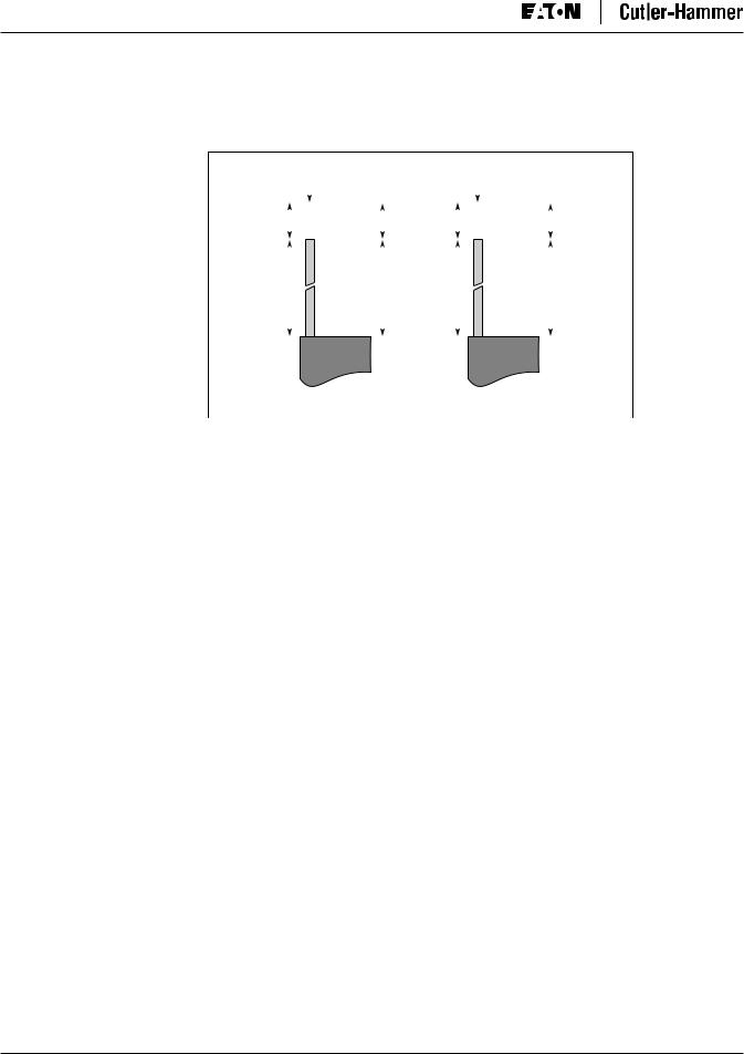
1. Strip the motor and input power cables as shown in Figure 3-1 and Table 3-7.
|
Ground |
|
|
|
|
|
|
|
Ground |
|||||||||||
|
|
|
|
|
|
|
|
|
|
|
|
|
|
|
|
|
|
|
|
C2 |
|
|
|
|
|
|
|
|
|
|
|
|
|
|
|
|
|
|
|
|
|
A1 |
|
|
|
|
|
|
|
C1 |
A2 |
|
|
|
|
|
|
|
|
|
||
|
|
|
|
|
|
|
|
|
D1 |
B2 |
|
|
|
|
|
|
|
|
|
D2 |
B1 |
|
|
|
|
|
|
|
|
|
|
|
|
|
|
|
|
|
|||
|
|
|
|
|
|
|
|
|
|
|
|
|
|
|
|
|
|
|
|
|
|
|
|
|
|
|
|
|
|
|
|
|
|
|
|
|
|
|
|
|
|
|
|
|
|
|
|
Power |
|
|
Motor |
|
|
|
|
|
|
|
|
|
|
|
|
|
|
|
|
|
|
|
|
|
|
|
|
|
Figure 3-1: Input Power and Motor Cable Stripping |
|
|
|||||||
|
|
|
|
|
|
|
and Wire Lengths |
|
|
|
|
|||
Cable Stripping Lengths for Power and Motor Cables |
|
|
|
|
|
|
|
|||||||
|
Table 3-7: Power and Motor Cable Stripping Lengths |
|
|
|
|
|
|
|||||||
|
|
|
|
|
|
|
|
|
|
|
|
|
|
|
|
Product |
|
|
Frame |
Power Wiring in Inches (mm) |
|
Motor Wiring in Inches (mm) |
|||||||
|
|
|
|
|
|
|
|
|
|
|
|
|
|
|
|
hp |
|
Voltage |
Size |
A1 |
B1 |
C1 |
D1 |
|
A2 |
B2 |
C2 |
D2 |
|
|
|
|
|
|
|
|
|
|
|
|
|
|
||
|
|
|
|
|
|
|
|
|
|
|
|
|
||
|
3/4 – 3 |
230V |
FR4 |
0.59 |
1.38 |
0.39 |
0.79 |
|
0.28 |
1.97 |
0.28 |
1.38 |
||
|
1 – 5 |
480V |
|
(15) |
(35) |
(10) |
(20) |
|
(7) |
(50) |
(7) |
(35) |
||
|
|
|
|
|
|
|
|
|
|
|
|
|
||
|
5 – 7-1/2 |
230V |
FR5 |
0.79 |
1.57 |
0.39 |
1.18 |
|
0.79 |
2.36 |
0.39 |
1.57 |
||
|
7-1/2 – 15 |
480V |
|
(20) |
(40) |
(10) |
(30) |
|
(20) |
(60) |
(10) |
(40) |
||
|
|
|
|
|
|
|
|
|
|
|
|
|
|
|
|
10 |
– 15 |
230V |
FR6 |
0.79 |
3.54 |
0.59 |
2.36 |
|
0.79 |
3.54 |
0.59 |
2.36 |
|
|
20 |
– 30 |
480V |
|
(20) |
(90) |
(15) |
(60) |
|
(20) |
(90) |
(15) |
(60) |
|
|
2 – 25 |
575V |
|
|
|
|
|
|
|
|
|
|
||
|
|
|
|
|
|
|
|
|
|
|
|
|
|
|
|
20 |
– 30 |
230V |
FR7 |
0.98 |
4.72 |
0.98 |
4.72 |
|
0.98 |
4.72 |
0.98 |
4.72 |
|
|
40 |
– 60 |
480V |
|
(25) |
(120) |
(25) |
(120) |
|
(25) |
(120) |
(25) |
(120) |
|
|
30 |
– 40 |
575V |
|
|
|
|
|
|
|
|
|
|
|
|
|
|
|
|
|
|
|
|
|
|
|
|
|
|
|
75 |
– 125 |
480V |
FR8 |
1.10 |
9.45 |
1.10 |
9.45 |
|
1.10 |
9.45 |
1.10 |
9.45 |
|
|
50 |
– 75 |
575V |
|
(28) |
(240) |
(28) |
(240) |
|
(28) |
(240) |
(28) |
(240) |
|
|
|
|
|
|
|
|
|
|
|
|
|
|
||
|
150 – 200 |
480V |
FR9 |
1.10 |
11.61 |
1.10 |
11.61 |
|
1.10 |
11.61 |
1.10 |
11.61 |
||
|
100 – 300 |
575V |
|
(28) |
(295) |
(28) |
(295) |
|
(28) |
(295) |
(28) |
(295) |
||
|
|
|
|
|
|
|
|
|
|
|
|
|
|
|
3-4 |
For more information visit: www.eatonelectrical.com |
MN04003002E |
SVX9000 AF Drive User Manual
April 2004
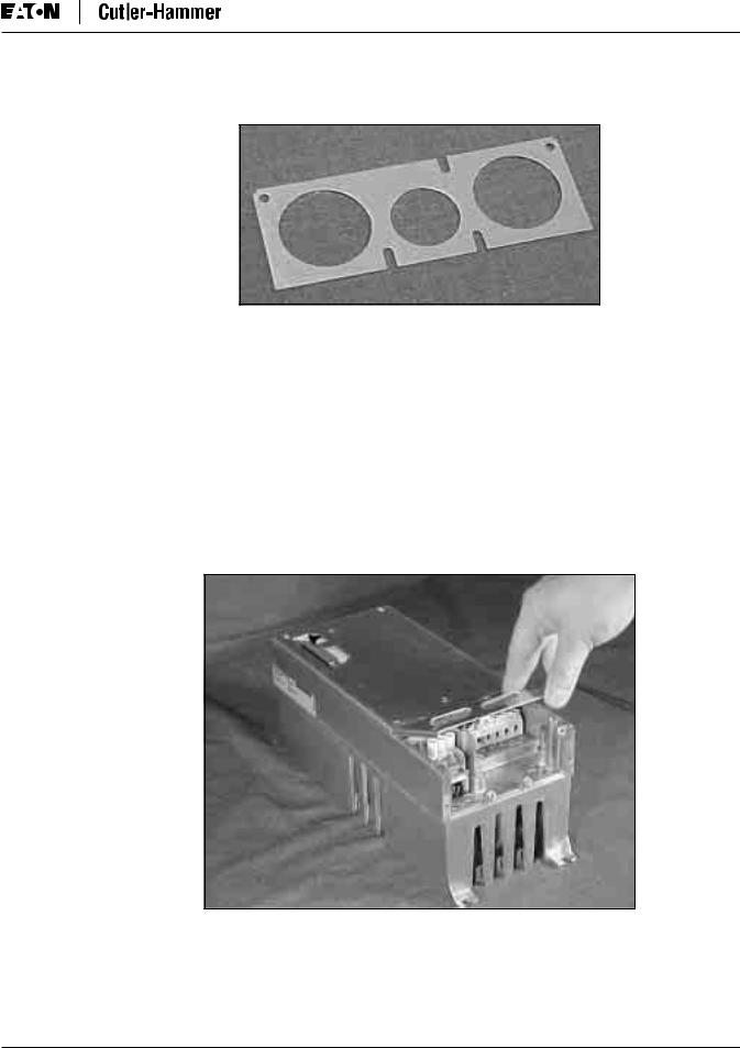
2. Locate the plastic bag containing the wiring plate.
Figure 3-2: Wiring Plate
3.If conduit is being used, attach the wiring plate to drive then conduit.
4.Pass the motor and input power wires/cables through the holes of the wiring plate.
5.Connect the input power and motor and control wires to their respective terminals according to the wiring diagrams in the section marked “Standard Wiring Diagrams and Terminal Locations” on Page 3-7.
6.If an optional external brake resistor is used, connect its cable to the appropriate terminals. See “Standard Wiring Diagrams and Terminal Locations.”
7.If shielded cable is used, connect the shields of the input line power cable and the motor cable to the ground terminals of the SVX9000 drive, the motor and the line power supply.
Figure 3-3: Ground Terminal Locations
8.If shielded cable is not used, check the connection of the ground cable to the motor, the SVX9000 drive and the input line power terminals marked with  .
.
MN04003002E |
For more information visit: www.eatonelectrical.com |
3-5 |
SVX9000 AF Drive User Manual
April 2004
9.Attach the wiring plate with the screws provided. Ensure that no wires are trapped between the frame and the wiring plate.
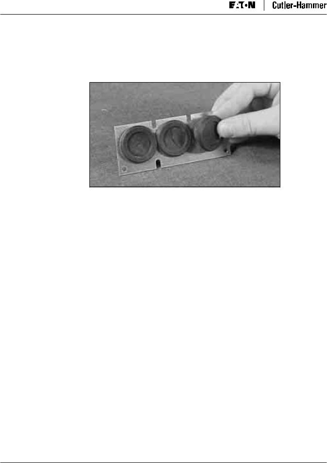
10.Insert the rubber grommets supplied into the wiring plate holes that have not been used, as illustrated in Figure 3-4.
Figure 3-4: Cable Protection Plate
3-6 |
For more information visit: www.eatonelectrical.com |
MN04003002E |
SVX9000 AF Drive User Manual
April 2004
Standard Wiring Diagrams and Terminal Locations
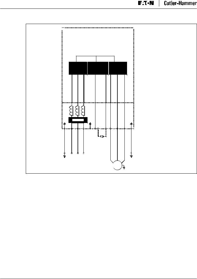
The following wiring diagrams show the line and motor connections of the frequency converter.
Power
Board
230V 3/4 - 15 hp
480V 1 - 30 hp
575V 2 - 25 hp
|
|
|
|
|
|
|
|
|
Control |
|
|
|
|
|
|
|
|||
|
|
|
|
|
|
|
|
|
Board |
|
|
|
|
|
|
|
|
|
|
|
|
|
|
|
|
|
|
||
|
|
L1 L2 L3 |
R- U V W |
||||||
|
|
|
|
|
|
DCDC+/ |
|
|
|
|
|
|
|
|
|
R+ |
|
|
Note: |
|
|
|
|
|
|
|
|
|
Integrated Brake |
|
|
|
|
|
|
|
|
|
Chopper Circuit Not |
|
|
|
|
|
|
|
|
|
Included on 575V units. |
|
|
|
|
|
|
BR |
|
|
|
|
|
|
|
|
|
Option |
|
|
|
L1 L2 L3 See
Note
M 3~
Figure 3-5: Principle Wiring Diagram of SVX Power Unit,
FR4 to FR5 and FR6
Note: When using a 1-phase supply, for units rated for such, connect the input power to terminals L1 and L2. Consult Eaton Electrical for more information.
MN04003002E |
For more information visit: www.eatonelectrical.com |
3-7 |
SVX9000 AF Drive User Manual
April 2004
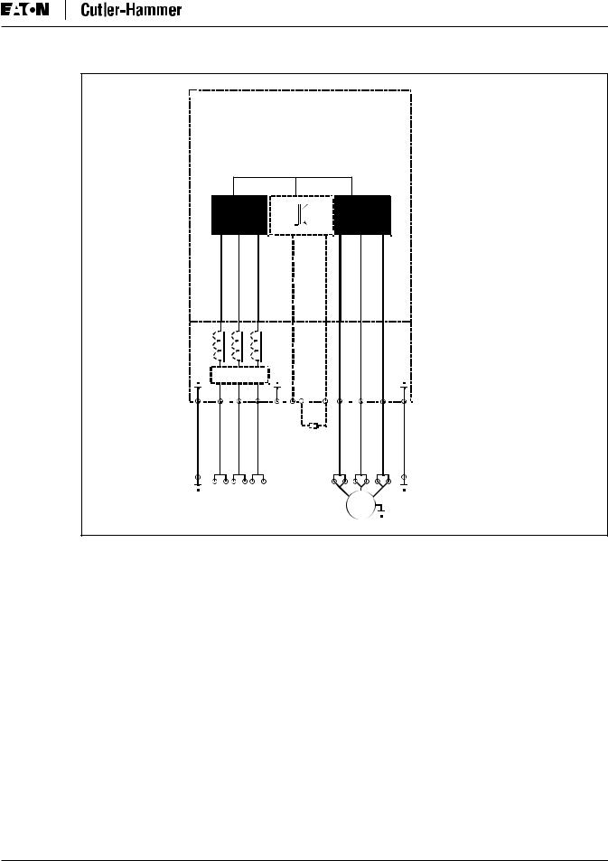
Power
Board
230V 20 - 30 hp
480V 40 - 125 hp
575V 30 - 75 hp
Control
Board
RFI Filter
DC+/
L1 L2 L3 R+ R- U V W
DC-
BR
Option
Note:
Integrated Brake
Chopper Circuit Not
Included on 575V units.
L1 L2 L3
See
Note
M 3~
Figure 3-6: Principle Wiring Diagram of SVX Power Unit,
FR6, FR7 and FR8
Note: When using a 1-phase supply, for units rated for such, connect the input power to terminals L1 and L2. Consult Eaton Electrical for more information.
3-8 |
For more information visit: www.eatonelectrical.com |
MN04003002E |
SVX9000 AF Drive User Manual
April 2004
Power
Board
480V 150 - 350 hp
575V 100 - 300 hp
Control
Board
|
|
RFI Filter |
|
|
DC+/ |
|
||||||||
|
|
|
|
|
|
|
|
|||||||
|
|
|
|
|
|
|
|
|||||||
|
|
L1 |
L2 |
|
L3 |
|
R+ R- U V W |
|
||||||
|
|
|
|
|
|
|
DC- |
|
||||||
|
|
|
|
|
|
|
BR |
|
||||||
|
|
|
|
|
|
|
Option |
|
||||||
|
L1 |
L2 |
L3 |
|
|
|
|
|
|
|
|
|
||
|
|
|
|
|
|
|
|
|
|
|||||
|
See |
|
|
|
|
|
|
|
|
|
||||
|
|
|
|
M |
|
|||||||||
|
Note |
|
|
|
|
|
|
|
|
|||||
|
|
|
3~ |
|
|
|
||||||||
Figure 3-7: Principle Wiring Diagram of SVX Power Unit,
FR9 to FR10
The dotted lines refer to components present in FR9 but not in FR10.
Note: When using a 1-phase supply, for units rated for such, connect the input power to terminals L1 and L2. Consult Eaton Electrical for more information.
MN04003002E |
For more information visit: www.eatonelectrical.com |
3-9 |
SVX9000 AF Drive User Manual
April 2004
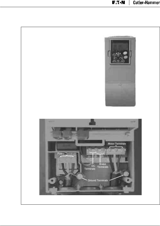
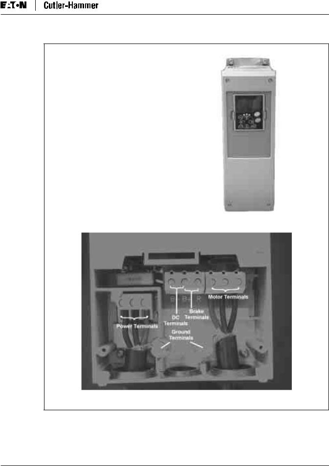
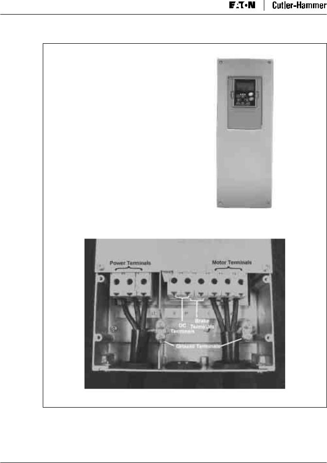
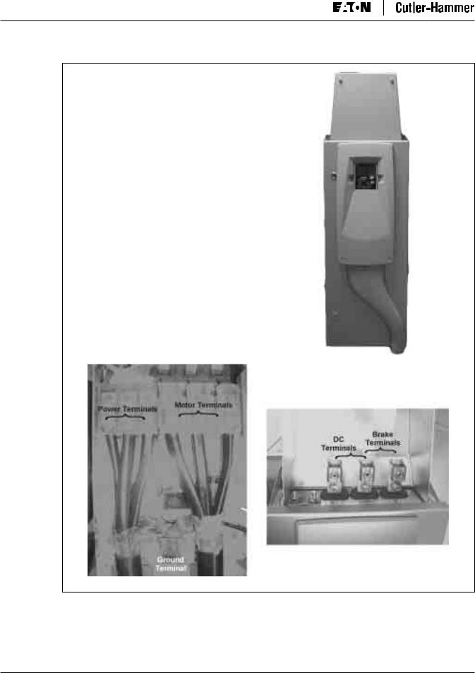
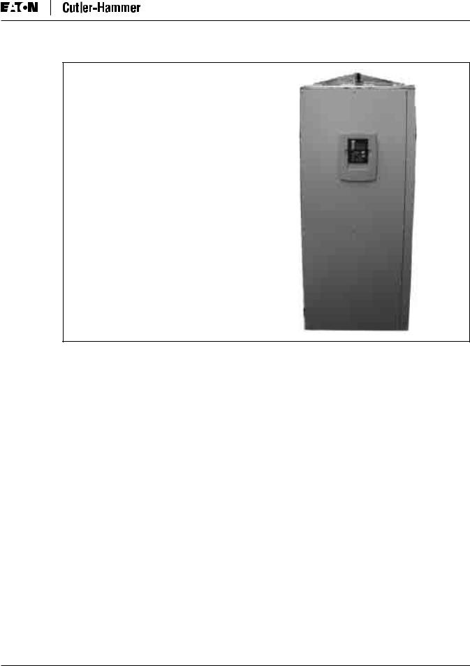
Power and Motor Wiring Terminal Photos
230V, 3/4 – 3 hp 480V, 1 – 5 hp
Frame Size: FR4
Figure 3-8: FR4 Power and Motor Wiring Terminals
3-10 |
For more information visit: www.eatonelectrical.com |
MN04003002E |
SVX9000 AF Drive User Manual
April 2004
230V, 5 – 7-1/2 hp 480V, 7-1/2 – 15 hp
Frame Size: FR5
Figure 3-9: FR5 Power and Motor Wiring Terminals
MN04003002E |
For more information visit: www.eatonelectrical.com |
3-11 |
SVX9000 AF Drive User Manual
April 2004
230V, 10 – 15 hp 480V, 20 – 30 hp 575V, 2 – 25 hp
Frame Size: FR6
Figure 3-10: FR6 Power and Motor Wiring Terminals
3-12 |
For more information visit: www.eatonelectrical.com |
MN04003002E |

SVX9000 AF Drive User Manual
April 2004
230V, 20 – 30 hp 480V, 40 – 60 hp 575V, 30 – 40 hp
Frame Size: FR7
Figure 3-11: FR7 Power and Motor Wiring Terminals
MN04003002E |
For more information visit: www.eatonelectrical.com |
3-13 |
SVX9000 AF Drive User Manual
April 2004
Supplied only when |
{ |
Brake Chopper |
|
included with Drive. |
480V, 75 – 125 hp 575V, 50 – 75 hp
Frame Size: FR8
Figure 3-12: FR8 Power and Motor Wiring Terminals
3-14 |
For more information visit: www.eatonelectrical.com |
MN04003002E |
SVX9000 AF Drive User Manual
April 2004
480V, 150 – 200 hp 575V, 100 – 175 hp
Frame Size: FR9
Figure 3-13: FR9 Power and Motor Wiring Terminals
MN04003002E |
For more information visit: www.eatonelectrical.com |
3-15 |

SVX9000 AF Drive User Manual
April 2004
Checking the Cable and Motor Insulation
1.Check the motor cable insulation as follows:
●Disconnect the motor cable from terminals U, V and W of the SVX9000 and from the motor.
●Measure the insulation resistance of the motor cable between each phase conductor as well as between each phase conductor and the protective ground conductor.
●The insulation resistance must be >1 MΩ .
2.Check the input power cable insulation as follows:
●Disconnect the input power cable from terminals L1, L2 and L3 of the SVX9000 and from the utility line feeder.
●Measure the insulation resistance of the input power cable between each phase conductor as well as between each phase conductor and the protective ground conductor.
●The insulation resistance must be >1 MΩ .
3.Check the motor insulation as follows:
●Disconnect the motor cable from the motor and open any bridging connections in the motor connection box.
●Measure the insulation resistance of each motor winding. The measurement voltage must equal at least the motor nominal voltage but not exceed 1000V.
●The insulation resistance must be >1 MΩ .
3-16 |
For more information visit: www.eatonelectrical.com |
MN04003002E |
 Loading...