


 Loading...
System Introduction
|
S E C T I O N |
1 |
|
1.1Specifications
Control Panel Specifications
Flexible Zone Configuration:
•8 Fully Programmable Zones
•38 Access Codes: 32 User, 1 System Master, 2 Partition Master, 2 Duress and 1 maintenance
•Expandable to 32 Zones
•Keypads with zone inputs available (PC/KP5508Z, PC/KP5516Z, PC/KP5532Z, LCD/KPL5500Z)
•Hardwired expansion available using the PC5108 Eight Zone Expansion Module
•Wireless expansion available using the PC5132 Wireless Zone Expansion Module (up to 32 wireless zones, 900MHz, True Spread Spectrum Technology, Fully Supervised)
•Normally Closed, Single EOL, or Double EOL zone supervision
•2-Wire Smoke Input (via PGM2 input)
•27 Zone Types, 8 Programmable Zone Options
•2 Partitions
Audible Alarm Output:
•Supervised Bell Output (current limited at 3 amps), 12 VDC
•Steady or Pulsed Output
EEPROM Memory:
• Will not lose programming or system status on complete AC and Battery failure
Programmable Outputs:
•Up to 14 Programmable Voltage Outputs, 23 programmable options
•One High Current (300 mA) PGM output with 2 wire smoke detector capability on main panel
•Maximum Loop Current is 1.5 mA when the 2-wire smoke detector configuration is used
•One Low Current (50 mA) PGM output on main panel
•Eight Additional Low Current (50 mA) PGM outputs available using the PC5208 module
•Four High Current (1 Amp) PGM outputs Available Using the PC5204 module
•1 PC5204 Output Fully Supervised for Siren Output
Powerful 1.5 Amp Regulated Power Supply:
•500 mA Auxiliary Supply, 12 VDC
•Positive Temperature Coefficient (PTC) components replace fuses
•Supervision for loss of AC Power, Low Battery
•Internal Clock Locked to AC Power Frequency
Power Requirements:
•Transformer = 16.5 VAC, 40VA
•Battery = 12 volt 4 Ah minimum rechargeable sealed lead acid
Remote Keypad Specifications: |
|
|
• 8 Different Keypads Available: |
|
|
- PC5508(Z)/KP5508(Z) 8 Zone LED Keypad |
- PC5532(Z)/KP5532(Z) 32 Zone LED Keypad |
|
- PC5516(Z)/KP5516(Z) 16 Zone LED Keypad |
- LCD5500(Z)/KPL5500 (Z) Alphanumeric Keypad |
|
• Each Keypad has 5 Fully Programmable Function Keys |
• Connect up to 8 Keypads |
|
• Four Wire (Quad) Connection to Keybus |
|
• Built in Piezoelectric Buzzer |
Digital Communicator Specifications: |
|
|
• Supports all Major Formats including SIA and Contact ID |
• Event Initiated Personal Paging |
|
• 3 Programmable Phone Numbers |
|
• 2 Account numbers |
• Supports LINKS1000 Cellular Communication |
|
• DTMF and Pulse Dialing |
• DPDT Line Seizure |
|
• Anti-jam Feature |
• Split Reporting of Selected Transmissions to Each Telephone Number
System Supervision Features
The PC5010 continuously monitors a number of possible trouble conditions including:
• AC Power Failure |
• Trouble by Zone |
• Fire Trouble |
• Telephone Line Trouble |
• Low Battery Condition |
• Bell Output Trouble |
• Loss of Internal Clock |
• AUX Power Supply Fault |
• Tamper by Zone |
• Failure to Communicate |
• Module Fault (Supervisory or Tamper) |
|
1

S |
Y |
S |
T |
E |
M |
I |
N |
T |
R |
O |
D |
U |
C |
T |
I |
O |
N |
|
|
|
|
|
|
|
|
|
|
|
|
|
|
||||
|
|
False Alarm Prevention Features |
|
|
|
|
|
|
|
|
|
|
|
||||
|
|
• Audible Exit Delay |
|
• Audible Exit Fault |
|
|
•Urgency on Entry Delay |
|
|
|
|||||||
|
|
• Quick Exit |
|
|
• Swinger Shutdown |
|
|
• Recent Closing Transmission |
|
|
|||||||
|
|
• Communication Delay |
• Rotating Keypress Buffer |
|
•Cross Zone Police Code Alarm |
|
|
||||||||||
Additional Features
•Auto Arm by Partition at Specified Time
•Keypad Activated Alarm Output and Communicator Test
•Keypad Lockout
•Audio Capability using the PC5928 Audio Interface Module which allows local intercom and Central Station 2-Way Listen in.
•All modules connect to the system via a four wire Keybus up to 1000’/305m from main panel
•Event Buffer can be printed using PC5400 RS232 Serial Interface module
•Supports the Escort5580 Voice Prompt Module with Automation/Lighting Control
•128 Event Buffer, Time and Date Stamped
•Upload/Download Capability
1.2Additional Devices
1.2.1Keypads
A maximum of eight (8) keypads can be connected to the control panel and can be any combination of the following listed. Different keypads (with function keys) can be used for different size systems; 8 zone, 16 zone and 32 zone.
|
|
|
|
|
|
PC5508/PC5508Z |
PC5516 /PC5516Z |
PC5532/PC5532Z |
LCD5500/LCD5500Z |
||
KP5508/KP5508Z |
KP5516/KP5516Z |
KP5532/KP5532Z |
KPL5500/KPL5500Z |
||
8 zone LED keypad |
16 zone LED keypad |
32 zone LED keypad |
LCD keypad |
||
1.2.2PC5108 Eight Zone Expander Module
Eight zone expander module can be used to increase the number of zones on the system. Up to 3 modules can be connected to increase the system zones to a maximum of 32. (See PC5108 Installation Instructions Sheet.)
1.2.3PC5132 Wireless Receiver Module
The PC5132 Wireless Receiver module can be used to connect up to 32 wireless devices. All devices are spread spectrum, 900 MHz, fully supervised and use standard ‘AAA’ or ‘AA’ alkaline batteries (See Section 5.27 “Wireless Expansion”). (See PC5132 Installation Manual.)
Additional wireless devices are available:
WLS904 |
WLS906 |
WLS907 |
WLS908 |
WLS909 |
WLS910 |
WLS904 Wireless Motion Detector
The wireless Motion Detector can be used in conjunction with the PC5132 Wireless Receiver to include wireless space protection. The unit comes with four ‘AAA’ batteries.
WLS906 Wireless Smoke Detector
The wireless Smoke Detector can be used in conjunction with the PC5132 Wireless Receiver to include wireless smoke detection. The unit comes with six ‘AA’ batteries.
2

S Y S T E M I N T R O D U C T I O N
WLS907 Wireless Slimline Universal Transmitter
The wireless Slimline Universal Transmitter can be used with the PC5132 Wireless Receiver to add wireless door or window contacts in a smaller package. The unit comes with three ‘AAA’ batteries and has built-in contacts.
WLS908 Wireless Panic Pendant
The wireless Panic Pendant can be used in conjunction with the PC5132 Wireless Receiver to include personal wireless protection. The unit comes with 1 mini 12V battery.
It is a disposable transmitter in that it is Ultrasonically welded together and the battery is not user changeable.
WLS909 Wireless Key
The Wireless Key can be used in conjunction with the PC5132 Wireless Receiver to include a simple and mobile method of arming and disarming the system. The unit comes with three Photo/Electronic 1.5V batteries. This system can have a maximum of 16 Wireless Keys.
WLS910 Wireless Handheld Keypad (This device is not UL Listed)
The wireless Handheld Keypad can be used in conjunction with the PC5132 Wireless Receiver to include a simple and mobile method of arming and disarming the system. The unit comes with three ‘AAA’ batteries. The system can have a maximum of four wireless Handheld Keypads.
1.2.4PC5100 Addressable Service Interface Module
The PC5100 will allow addressable multiplex loop devices to be added to the system. These devices use a 2-wire connection for power and to communicate with the control panel. This, in combination with low power device, simplifies wiring and reduces device count for fast and efficient installation.
The available AML devices are as follows:
• AMS-220/200T Smoke Detector
• AMB-300 PIR Detector
• AMB-600 Dual PIR Detector
• AMA-100 Glassbreak Detector
• AMP-700 Contact Input Module
• AMP-701 Magnetic Door/Window Contact
For more information regarding the PC5100 and the AML devices, see their respective Installation Instructions.
1.2.5PC5204 Power Supply Output Module
The PC5204 can provide up to 1 Amp of additional power for modules or devices connected to the control panel. The module requires a 16.5 volt AC 40 VA transformer and 4 AH battery. In addition, the module provides 4 programmable high current voltage outputs. Each output is individually programmable with 19 PGM output options available (See Section 5.10 “PGM Outputs”). (See PC5204 Installation Instructions Sheet.)
1.2.6 PC5208 Eight Low Current Output Module
Adds eight low current outputs (50 mA) to the control. Each output is individu-
ally programmable with 19 PGM output options available (See Section 5.10 “PGM Outputs”). (See PC5208 Installation Instructions Sheet.)
1.2.7Escort5580 Module
This Escort5580 module will turn any touch tone phone into a fully functional keypad. The module also includes a built-in interface to control up to 32 line carrier type devices for lighting and temperature control (See Section 5.28 “Escort5580 Module”). (See Escort5580 Installation Manual.)
1.2.8PC5928 Audio Interface Module (This device is not UL Listed)
The PC5928 Audio Interface module is a simple way to incorporate paging, intercom, baby listen-in and door answer to the PC5010 control panel. The module also has built-in two-way voice capability for central station (See Section 5.30 “Audio Interface Module”).
3

S Y S T E M I N T R O D U C T I O N
Three additional devices are available (These devices are not UL Listed):
PC5921 Intercom Audio Station (This device is not UL Listed)
can be used in conjunction with the PC5928 Audio Interface Module.
PC5921 EXT Door Box Audio Station (This device is not UL
Listed) can be used in conjunction with the PC5928 Audio Interface Module.
PC5921 EXT/R Door Box Audio Station (This device is not UL
PC5921 PC5921 EXT PC5921 EXT/R Listed) can be used in conjunction with the PC5928 Audio Interface Module. The Door Box contains a relay so the normal door bell can be used instead of the internal one generated by the PC5928 module.
1.2.9PC5400 Printer Module
This PC5400 Printer Module will allow the panel to print out all events that occur on the system to any serial printer. All events will be printed with the Partition, time, date and the event that occurred (See Section 5.29 “On-site Printer”).
1.2.10LINKS1000 Cellular Communicator (This device is not UL Listed)
The LINKS1000 Cellular Communicator provides an efficient, cost-effective method for adding cellular back up. The unit comes in its own cabinet with antenna and requires a separate battery and transformer (See Section 5.26 “LINKS1000 cellular communicator”).
1.2.11Cabinets
Several different cabinets are available for the PC5010 modules. They are as follows:
PC5003C Main Control Cabinet for the PC5010 main panel. Dimensions 288mm x 298mm x 78mm / 11.3” x 11.7” x 3” approximately.
PC5002C Cabinet to house the PC5204 Power Supply Output Module. Dimensions 213mm x 235mm x 78mm / 8.4” x 9.25” x 3” approximately.
PC5004C Cabinet to house the Escort5580 Module and PC5400 Printer Module. Dimensions 229mm x 178mm x 65mm / 9” x 7” x 2.6” approximately.
PC5001C Cabinet to house the PC5108 Zone Expander Module and the PC5208 Eight Low Current Output Module. Dimensions 153mm x 122mm x 38mm / 6” x 4.8” x 1.5” approximately.
PC5001CP Plastic Cabinet to house the PC5108 Zone Expander Module and the PC5208 Eight Low Current Output Module. Dimensions 146mm x 105mm x 25.5mm / 5.75” x 4.2” x 1” approximately.
1.2.12Backplates
There are two different backplates available for keypads to locate an Audio Station next to the keypad:
PC55BP1 Backplate
This backplate is to be used when an Audio Station is to be located next to a keypad. Dimensions 208mm x 115mm x 18mm / 8.2” x 4.5” x 0.25” approximately.
PC55BP2 Backplate
This backplate is to be used when an Audio Station is to be located next to a keypad. In addition the backplate will allow you to mount a PC5108 Zone Expander Module or the PC5208 Eight Low Current Output Module. Dimensions 208mm x 115mm x 18mm / 8.2” x 4.5” x 0.7” approximately.
1.3Out of the Box
You should find the following equipment included in your system. Verify each of the components is included:
•one PC5010 main control cabinet
•one PC5010 main control circuit board
•one PC55XX(Z) (8 zone, 16 zone or 32 zone LED)/ LCD5500(Z) keypad
•one Installation Manual
•one Programming Worksheet Manual
•one Instruction Manual (LED or LCD keypad)
•one hardware pack consisting of:
-five plastic circuit board standoffs
-one 2200 ohm (2.2K) resistor
-seventeen 5600 ohm (5.6K) resistors
-one 1000 ohm (1K) resistor
4

Getting Started
|
S E C T I O N |
2 |
|
The following sections provide a complete description of how to wire and configure devices and zones.
2.1Installation Steps
The following steps are provided to assist with the installation of the panel. It is suggested that you read over this section briefly to get an overall understanding of the order of installation. Once this is done carefully work through each step. Working from this plan will help reduce problems and reduce the overall installation time required.
Step 1 Create a Layout
Draw a rough sketch of the building and include all alarm detection devices, zone expanders, keypads and all other modules that are required.
Step 2 Mounting the Panel
Locate the panel in a dry area, preferably located near an unswitched AC power source and the incoming telephone line. Before attaching the cabinet to the wall be sure to press the five circuit board mounting studs into the cabinet from the back.
 Complete all wiring before applying AC or connecting the battery.
Step 3 Wiring the Keybus (Section 2.3)
Wire the Keybus to each of the modules following the guidelines provided.
Step 4 Assigning Zones to Zone Expanders (Section 2.5)
If zone expander modules are being used the modules must be configured so the panel knows which zones are assigned to each expander. Follow the guideline provided to assign zones to expanders.
Step 5 Zone Wiring (Section 2.9)
Power down the control panel and complete all zone wiring. Follow the guidelines provided in Section 2.9 to connect zones using normally closed loops, single EOL resistor, double EOL resistors, Fire zones and Keyswitch Arming zones.
Step 6 Completing Wiring
Complete all other wiring including bells or sirens, phone line connections, ground connections or any other wiring necessary. Follow the guidelines provided in Section 2.2 “Terminal Descriptions”.
Step 7 Power up the Control Panel
Once all zone wiring and Keybus wiring is complete, power up the control panel.
 The panel will not power up if only the battery is connected.
Step 8 Keypad Assignment (Section 2.6)
Keypads must be assigned to different slots to be properly supervised. Follow the guideline provided in Section 2.6 to assign keypads.
Step 9 Enabling Supervision (Section 2.7)
After all modules have been wired to the Keybus, supervision must be enabled. Once supervision is enabled, the panel will be able to indicate module communication faults. Follow the guidelines provided in Section 2.7.
Step 10 Programming the System (Sections 4 and 5)
Section 4.0 provides a complete description of how to program the panel. Section 5.0 contains complete descriptions of the various programmable features, what options are available and how the options function. The Programming Work Sheets should be filled out completely before attempting to program the system.
Step 11 Testing the System
Test the panel completely to ensure that all features and functions are operating as programmed.
5

G E T T I N G S T A R T E D
2.2Terminal Descriptions
AC Terminals - AC
The panel requires a 16.5 volt, 40 VA transformer. Connect the transformer to an unswitched AC source and connect the transformer to these terminals.
 Do not connect the transformer until all other wiring is complete.
Battery Connection
The battery is used to provide back up power in the event of an AC power failure and to provide additional current when the panel demands exceed the power output of the transformer, such as when the panel is in alarm.
 Do not connect the battery until all other wiring is complete.
Connect the RED battery lead to the positive of the battery, the BLACK battery lead to the negative.
Auxiliary Power Terminals - AUX+ and GND
These terminals provide up to 500 mA of additional current at 12 VDC (rated 11.6 -12.6 VDC for UL residential applications) for devices requiring power. Connect the positive side of any device requiring power to the AUX+ terminal, the negative side to GND. The AUX output is protected; if too much current is drawn from these terminals (wiring short) the panel will temporarily shut off the output, until the problem is corrected.
Bell Output Terminals - BELL+ and BELL-
These terminals provide up to 3 Amps of current at 12 VDC (rated 11.6 -12.6 VDC for UL residential applications) (with stand-by battery; 700 mA continuous) for powering bells, sirens, strobes or other warning type equipment. Connect the positive side of any alarm warning device to BELL+, the negative side to BELL–. The BELL output is protected; if too much current is drawn from these terminals (wiring short) the BELL fuse will open.
The Bell output is supervised. If no alarm warning device is being used connect a 1000 ohm resistor across BELL+ and BELL– to prevent the panel from displaying a trouble condition (See Section 3.4 “[ ] Commands, [ ][2]”).
Keybus Terminals - RED, BLK, YEL, GRN
The Keybus is used by the panel to communicate with modules and by modules to communicate with the panel. Each module has four Keybus terminals that must be connected to the four Keybus terminals on the panel. For more information, see Section 2.3 “Keybus Operation and Wiring”.
Programmable Outputs - PGM1 and PGM2
Each PGM output is an open collector switch to ground. That is, when the PGM output is activated by the panel the terminal will switch to ground.
PGM1 can sink up to 50 mA of current to activate LEDs or a small buzzer. Connect the positive side of the LED or buzzer to AUX+, the negative side to PGM1. If more than 50 mA of current is required a relay must be used. Refer to the following diagram:
PGM2 is high current PGM (300mA) which operates similar to PGM1. It can be used for two wire smoke detectors (See Section 2.9 “Zone Wiring - Fire Zone Wiring”) with the jumper CON1 removed. Otherwise, the CON1 must remain on at all times.
Zone Input Terminals - Z1 to Z8
Each detection device must be connected to a zone on the control panel. It is suggested that each zone have one detection device however it is possible to wire multiple detection devices to the same zone. For zone wiring specifics, see Section 2.9 “Zone Wiring” .
Telephone Connection Terminals - TIP, RING, T-1, R-1
If a telephone line is required for central station communication or downloading, connect an RJ-31X jack in the following manner:
• RING - Red Wire _______ Incoming line from
|
|
|
|
|
|
|
|
|
|
|
|
|
|
|
|
• TIP - Green Wire |
telephone company |
|
|
|
|
|
|
|
|
|
|
|
|
|
|
|
|
• R-1 - Grey Wire ________ Outgoing line to |
|
|
|
|
|
|
|
|
|
|
|
|
|
|
|
|
|
||
|
|
|
|
|
|
|
|
|
|
|
|
|
|
|
|
||
|
|
|
|
|
|
|
|
|
|
|
|
|
|
|
|
• T-1 - Brown Wire |
house telephone(s) |
|
|
|
|
|
|
|
|
|
|
|
|
|
|
|
|
|
|
6
G E T T I N G S T A R T E D
Ensure the plugs and jacks meet the dimension, tolerance and metallic plating requirements of 47 C.F.R. Part 68, SubPart F.
For proper operation there must be no other telephone equipment connected between the control panel and the telephone company facilities.
Do not connect the alarm panel communicator to telephone lines intended for use with a FAX machine. These lines may incorporate a voice filter which disconnects the line if anything other than FAX signals are detected, resulting in incomplete transmissions.
2.3Keybus Operation and Wiring
The Keybus is used by the panel to communicate with all modules connected and by the modules to talk to the panel. The RED and BLK terminals are used to provide power while YEL and GRN are clock and data.
 The 4 Keybus terminals of the panel must be connected to the 4 Keybus terminals or wires of all modules.
The following conditions apply:
•Keybus should be run in minimum 22 gauge quad (0.5mm), two pair twist preferred
•the modules can be home run to the panel, connected in series or can be T-tapped
•any module can be connected anywhere along the Keybus, you do not need a separate Keybus wire run for keypads, zone expanders etc.
•no module can be more than 1,000'/305m (in wire length) from the panel
•shielded wire is not necessary unless wires are run in an area that may present excessive RF noise or interference
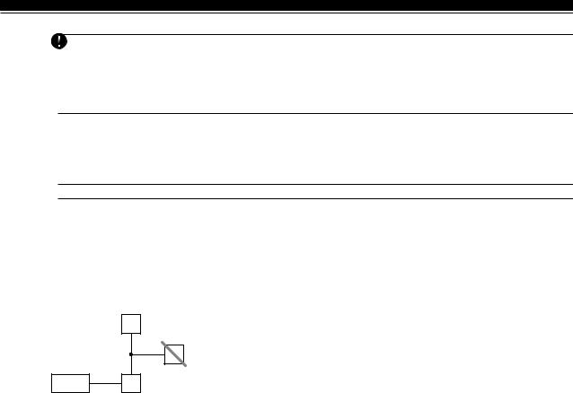
Example of Keybus Wiring
B
150'
500' C
150'
PANEL 500' A
NOTE: Module (A) is wired correctly as it is within 1,000'/305m of the panel, in wire distance.
Module (B) is wired correctly as it is within 1,000'/305m of the panel, in wire distance
Module (C) is NOT wired correctly as it is further than 1,000'/ 305m from the panel, in wire distance.
2.4Current Ratings - Modules and Accessories
In order for the Power 832 system to operate properly, the power output capabilities of the main control and expansion devices must not be exceeded. Use the data presented below to ensure that no part of the system is overloaded and cannot function properly.
System Outputs (all 12 VDC)
• PC5010 VAUX: 500 mA. Includes one keypad. Subtract for each additional keypad, expansion module and accessory connected to VAUX or Keybus.
BELL: 700 mA. Continuous Rating.
3.0A. Short Term. Available only with stand-by battery connected.
•PC5204 VAUX: 1.0 A. Continuous Rating. Subtract for each device connected.
3.0A. Short Term. Available only with stand-by battery connected.
•PC5208 VAUX: 250 mA. Subtract for each device connected. Subtract the total load on this terminal
from the PC5010 VAUX/Keybus output.
• PC5100 VAUX: 100 mA. Subtract for each device connected. Subtract the total load on this terminal from the PC5010 VAUX/Keybus output.
• PC5108 VAUX: 100 mA. Subtract for each device connected. Subtract the total load on this terminal from the PC5010 VAUX/Keybus output.
PC5010 Device Ratings (@ 12 VDC) |
|
• LCD5500 Keypad: 50 mA |
• PC5208 Output Module: 50 mA |
• PC5532 Keypad: 45 mA |
• PC5132 Wireless Module: 125 mA |
• PC5516 Keypad: 45 mA |
• PC5100 Addressable Service Interface Module: 40 mA |
• PC5508 Keypad: 45 mA |
• Escort5580 Module: 150 mA |
• LCD5500Z Keypad: 85 mA |
• PC5928 Audio Interface Module: 65 mA |
• PC5532Z Keypad: 85 mA |
• PC5921 Intercom Audio Station: 20 mA |
• PC5516Z Keypad: 85 mA |
• PC5921 EXT Door Box Audio Station: 20 mA |
• PC5508Z Keypad: 85 mA |
• PC5921 EXT/R Door Box Audio Station: 35 mA |
• PC5108 Zone Module: 35 mA |
• PC5400 Printer Module: 65 mA |
• PC5204 Output Module: 20 mA |
|
7

G E T T I N G S T A R T E D
Other Devices
Read the manufacturer’s literature carefully to determine the maximum current requirement (during activation or alarm) and use this value for loading calculations. Do not allow connected devices to exceed the system capabilities during any possible operational mode.
2.5Assigning Zones to Zone Expanders
The main panel contains zones 1 to 8. Additional zone expanders may be added to increase the number of zones on the system. Each zone expander consists of two groups of 4 zones and each group must be configured to assign the specific zones to the expander. This is done by setting the jumpers located on the expander to the proper settings.
Before a zone expander will work properly the jumpers must be set so the panel can determine the correct zone assignment.
The following are the jumper settings for different zone assignments:
Expander Zones |
|
Jumpers |
|
System Zones Assigned |
Group A (Zones 1-4) |
J1 |
J2 |
J3 |
|
Group B (Zones 5-8) |
J4 |
J5 |
J6 |
|
|
ON |
ON |
ON |
Zones not enabled for hardware operation |
|
OFF |
ON |
ON |
Zones not enabled for hardware operation |
|
ON |
OFF |
ON |
Zones 9 - 12 |
|
OFF |
OFF |
ON |
Zones 13 - 16 |
|
ON |
ON |
OFF |
Zones 17 - 20 |
|
OFF |
ON |
OFF |
Zones 21 - 24 |
|
ON |
OFF |
OFF |
Zones 25 - 28 |
|
OFF |
OFF |
OFF |
Zones 29 - 32 |
The following is a diagram of the zone expander and where the jumper switches are located.
 There are two sets of jumpers, one set for the first 4 zones of the expander and one set for the other 4 zones.
In this diagram the jumpers settings shown indicate the first group of four zones of the expander will be zones 9 to 12 and the second group of 4 zones will be 13 to 16.
A group of zones can be disabled if they are not required for the installation.
In the above diagram the jumpers settings shown indicate the first group of four zones of the expander will be zones 9 to 12 and the second group of 4 zones will be 13 to 16.
A group of zones can be disabled if they are not required for the installation.
8

G E T T I N G S T A R T E D
2.6Keypad Assignment
There are 8 available slots for keypads. LED keypads by default are always assigned to slot 1 while the LCD5500Z is always assigned to slot 8. Keypads can each be assigned to a different slot (1 to 8) which offers two advantages. The panel can supervise the keypad connection to indicate a trouble condition if it is removed. Also keypads can be assigned to operate a specific partition or operate as a global keypad.
2.6.1How to Assign Keypads
 All keypad assignment must be done individually on each keypad on the system.
To assign a keypad to a slot and select the partition it will operate, enter the following: Step 1 — Enter Installer Programming
Step 2 — Press [000] for Keypad Programming
Step 3 — Press [0] for Partition and Slot Assignment
Enter a two digit number to specify the partition and slot assignment. 1st digit Enter 0 for Global Keypad;
Enter 1 for Partition 1 Keypad; Enter 2 for Partition 2 Keypad
2nd digit Enter 1 to 8 for Slot Assignment
Press the [#] key twice to exit programming. Continue this procedure at each keypad until all have been assigned to the correct slot.
2.6.2How to Program Function Keys
Each of the 5 Function Keys on each keypad may be programmed for different operation on each keypad.
Step 1 - Enter Installer Programming.
Step 2 - Press [000] for Keypad Programming.
Step 3 - Enter [1] to [5] to select Function Key to program.
Step 4 - Enter the 2 digit number, [00] to [21] for option.
Step 5 - Continue from Step 3 until all Function Keys are programmed.
Step 6 - Press [#] key twice to exit Installer Programming.
For a complete list of Function Key options See Section 3.5.1 “Function Key Options” .
2.7Enable Supervision
Once all the Keybus connections have been made, supervision must be enabled so the panel can indicate a trouble if a module is removed from the system.
To enable supervision, enter the following at any keypad:
Step 1 - Press [ ] [8] [Installer Code] to enter Installer Programming.
Step 2 - Press [902] to enable supervision. The panel will automatically search for all modules on the system. Once the search (it will take about 1 minute) is complete enter the following to confirm the modules on the system.
Step 3 - Press [903] to display all modules.
Zone lights will be turned on according to what modules the panel has found on the system. The LCD keypad will allow you to scroll through the modules. Refer to the following chart:
Light |
[1] ....... |
Keypad 1 present |
Light [13] ....... |
Zones 25 to 28 present |
Light |
[2] ....... |
Keypad 2 present |
Light [14] ....... |
Zones 29 to 32 present |
Light |
[3] ....... |
Keypad 3 present |
Light [15] ....... |
N/A (not used) |
Light |
[4] ....... |
Keypad 4 present |
Light [16] ....... |
N/A (not used) |
Light |
[5] ....... |
Keypad 5 present |
Light [17] ....... |
Module PC5132 present |
Light |
[6] ....... |
Keypad 6 present |
Light [18] ....... |
Module PC5208 present |
Light |
[7] ....... |
Keypad 7 present |
Light [19] ....... |
Module PC5204 present |
Light |
[8] ....... |
Keypad 8 present |
Light [20] ....... |
Module PC5400 present |
Light |
[9] ....... |
Zones 9 to 12 present |
Light [21] ....... |
Module PC5928 present |
Light [10] ....... |
Zones 13 to 16 present |
Light [22] ....... |
Module LINKS2X50 present |
|
Light [11] ....... |
Zones 17 to 20 present |
Light [23] ....... |
N/A |
|
Light [12] ....... |
Zones 21 to 24 present |
Light [24] ....... |
Escort5580 module present |
|
If a module is connected but does not show as being present, it may be due to any of the following reasons:
•it is not connected to the Keybus
•if there is a Keybus wiring problem
•if the module is more than 1,000'/305m from the panel
•if the module does not have enough power
•if the PC5132 does not have any devices added
9
G E T T I N G S T A R T E D
2.8Removing Modules
If a module is no longer required on the system the panel must be told to no longer supervise the module. To do this remove the module from the Keybus and perform the Enable supervision function again (See Section
2.7 “Enable Supervision”). The panel will see the module has been removed and will no longer supervise it.
2.9Zone Wiring
For a complete description of the operation of all zone types, please refer to Section 5.1 (“Zone Definitions”).
There are several different ways in which zones may be wired, depending on which programming options have been selected. The panel can be programmed to supervise normally closed, End of Line, or Double End of Line loops. Please refer to the following diagrams to study each type of individually supervised zone wiring.
Any zone programmed for Fire or 24 Hour Supervisory must be wired with a single End of Line (EOL) resistor regardless of the type of zone wiring supervision selected for the panel (section [013], options [1] and [2]). See Section 5.2 “Zone Programming.”
If you change the zone supervision options from DEOL to EOL or from NC to DEOL (section [013], options [1] or [2]), you should power down the system completely, and then power it back up. If you do not, the zones may not work correctly.
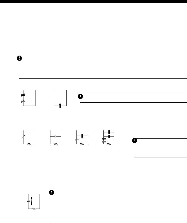
2.9.1Normally Closed (NC) Loops
ANY Z ANY COM |
ANY Z ANY COM |
TERMINAL TERMINAL |
TERMINALTERMINAL |
To enable normally closed loops, programming section [013], option [1] must be ON.
This option should only be selected if Normally Closed (NC) detection devices or contacts are being used.
2 NORMALLY CLOSED |
NORMALLY CLOSED |
CONTACTS WITH |
CONTACT; |
NO END OF LINE |
NO END OF LINE |
RESISTOR |
RESISTOR |
Normally Closed Loops ........................ |
Section [013], Option [1] |
2.9.2Single End Of Line (EOL) Resistors (5600Ω)
ANY Z ANY COM |
ANY Z ANY COM |
ANY Z ANY COM |
ANY Z ANY COM |
TERMINAL TERMINAL |
TERMINALTERMINAL |
TERMINAL TERMINAL |
TERMINALTERMINAL |
NORMALLY CLOSED |
NORMALLY OPEN |
1 NORMALLY OPEN |
2 NORMALLY OPEN |
CONTACT WITH |
CONTACTS WITH |
CONTACT AND |
CONTACT AND |
5600 Ω END OF LINE |
5600 Ω END OF LINE |
1 NORMALLY CLOSED |
2 NORMALLY CLOSED |
RESISTOR |
RESISTOR |
CONTACT WITH |
CONTACT WITH |
|
|
5600 Ω END OF LINE |
5600 Ω END OF LINE |
|
|
RESISTOR |
RESISTOR |
End of Line Resistors ............................................. |
Section [013], Option [1] |
||
Single End of Line Resistors .................................. |
Section [013], Option [2] |
||
To enable panel detection of single end of line resistors, programming section [013], options [1] and [2] must be OFF.
This option should be selected if either Normally Closed (NC) or Normally Open (NO) detection devices or contacts are being used.
2.9.3Double End of Line (DEOL) Resistors
Double End of Line resistors allow the panel to determine if the zone is in alarm, tampered or faulted.
To enable panel detection of double end of line resistors, programming section [013], option [1] must be
OFF and option [2] must be ON.
ANY Z ANY COM TERMINALTERMINAL
ALARM
CONTACT
DOUBLE EOL CIRCUIT 1 NORMALLY CLOSED CONTACT WITH 5600Ω END OF LINE RESISTORS
If the Double EOL supervision option is enabled, all hardwire zones must be wired for Double EOL resistors, except for Fire and 24 Hour Supervisory zones.
Do not wire DEOL resistors on keypad zones.
Do not use DEOL resistors for Fire zones or 24 Hour Supervisory zones. Do not wire Fire zones to keypad zone terminals if the DEOL supervision option is selected. This option can only be selected if Normally Closed (NC) detection devices or contacts are being used.
Only one NC contact can be connected to each zone. Wiring multiple detection devices or contacts on a single loop is not allowed.
The following chart shows zone status under certain conditions:
Loop Resistance |
Loop Status |
0Ω (shorted wire, loop shorted) |
Fault |
5600Ω (contact closed) |
Secure |
Infinite (broken wire, loop open) |
Tamper |
11200Ω (contact open) |
Violated |
End-of-Line Resistors ............................................. |
Section [013], Option [1] |
Double End-of-Line Resistors ................................ |
Section [013], Option [2] |
10

G E T T I N G S T A R T E D
2.9.4Fire Zone Wiring - 4 wire Smoke Detectors
All zones defined as Fire (See Section 5.1 “Zone Definitions”) must be wired according to the following diagram:
For a complete description of how fire zones operate, see Section 5.1 “Zone Definitions”.
2.9.5Fire Zone Wiring - 2 wire Smoke Detectors
If PGM2 has been programmed for 2 Wire Smoke Detector connection (See Section 5.10 “PGM Output”), the detectors must be wired according to the following diagram:
+ |
|
|
For a complete description of how fire zones operate, see |
|
|
Section 5.1 “Zone Definitions”. |
|
|
|
|
|
|
- |
|
If PGM2 is programmed for 2 wire smoke support, Jumper |
|
Ω |
CON1 on the main board must be removed. |
|
|
|
||
|
|
|
|
|
+ |
|
|
2.9.6Keyswitch Zone Wiring
Zones may be programmed to be used as keyswitch arming zones and must be wired according to the following diagrams:
For a complete description of how keyswitch zones operate, see Section 5.1 “Zone Definitions”.
Ω |
|
|
Ω |
|
|
2.9.7LINKS Supervisory (24 Hour Supervisory)
When using the LINKS1000 cellular communicator, any main board zone may be configured for LINKS Supervision. Program this zone as zone type [09], 24 Hour Supervisory in section [001].
With a 24 Hour Supervisory zone, if the LINKS1000 experiences a trouble, the zone will be violated, causing the panel to report the event to the central station. This type of zone always requires a single EOL resistor (5600Ω). Wire this zone according to the diagram.
2.9.8LINKS Answer
If the LINKS1000 cellular communicator is being used a zone may be configured for LINKS Answer to allow downloading to be performed in the event of phone line failure.
When the LINKS receives a phone call it will activate the RING terminal on the LINKS circuit board. This terminal can be used to violate a zone programmed as LINKS Answer (See Section 5.1 “Zone Definitions”), causing the panel to seize the phone line and begin communication with the downloading computer.
The zone programmed as LINKS Answer ALWAYS requires a single EOL resistor (5600Ω) and must be wired according to this diagram.
The LINKS Answer zone is only required for downloading to the panel via the LINKS.
When using the LINKS, Busy Tone Detection must not be used.
Keypad zones cannot be used for 24 Hour Supervisory or LINKS Answer.
11

G E T T I N G S T A R T E D
2.10Keypad Zones
Keypads with zone inputs can be connected to devices such as door contacts. This saves you from running wires back to the control panel for every device.
To install the keypad, open the keypad plastic by removing the screw at the bottom of the unit. Locate the five terminals on the keypad circuit board. Connect the four Keybus wires from the control panel: the red wire to R, the black to B, the yellow to Y and the green to G.
To connect the zone, run one wire to the Z terminal and the other to B. For powered devices, use red and black to supply power to the device. Run the red wire to the R (positive) terminal and the black wire to the B (negative) terminal.
When using end of line supervision, connect the zone according to one of the configurations outlined in Section 2.8 “Zone Wiring.” End of line resistors must be placed on the device end of the loop, not at the keypad.
 Keypad zones do not support DEOL resistors.
Assigning Keypad Zones
When using keypad zone inputs, each input used must be assigned a zone number in Installer’s Programming. First, ensure that you have enrolled all installed keypads into the desired slots. (See Section 2.6 “Keypad Assignment”).
Next, enter programming section [020] to assign the zones. There are eight programming locations in this section, one for each keypad slot. Enter a 2-digit zone number for each of the keypad zones. This number must be entered in the location corresponding to the keypad to which each zone is connected.
Keypad zones 1-8 will replace zone terminals Z1-Z8 on the control panel.
Once the keypad zones are assigned, you must also program zone definitions and zone attributes. (See also Section 5.1.1 “Assigning Keypad Zones”).
12

Keypad Commands
|
S E C T I O N |
3 |
|
All keypads provide complete information and control of the alarm panel. The panel can be completely programmed via any keypad on the system. LED keypads provide function indicator lights and individual zone indicator lights for the alarm circuits. The LCD keypad provides function indicator lights and word descriptions for zone status.
The following sections describe how to arm, disarm and perform other keypad functions.
3.1Access Codes
The panel has a total of 37 Access Codes available. |
|
|
||
• Access Codes [01] to [32] User Codes 1 to 32 |
• Access Code [40] ........... |
System Master Code |
||
• Access Code |
[33] ............ |
Partition Duress Code |
• Access Code [41] ........... |
Partition Master Code |
• Access Code |
[34] ............ |
Partition Duress Code |
• Access Code [42] ........... |
Partition Master Code |
System Master Code
The System Master Code Not Changeable option can be used to lock in the code. This will prevent the user from being able to change the System Master Code. If they attempt to change the code the keypad will sound a long error beep. The System Master Code can be used to arm or disarm any partition and perform any keypad function.
If the code is lost it can be reprogrammed through Installer Programming.
System Master Code Not Changeable .................. |
Section [015], Option [6] |
System Master Code .............................................. |
Section [007] |
Partition Master Codes
By default the Partition Master Codes are not programmed. They must be programmed by the System Master Code. A Partition Master Code, when first programmed, can act as a second master code and have the same access as the System Master Code. To program a Partition Master Code to operate on only one partition, you must change the code’s attributes (See Section 3.4). A Partition Master Code can program the access codes to operate on the Partition it is assigned to and program the Partition Duress Code.
Partition Duress Codes
By default Partition Duress Codes are not programmed. They must be programmed by the System Master Code or the Partition Master Code for that Partition. Once programmed if the Duress Code is used any time, the panel will activate a silent Duress alarm (See Section 5.7 “Communicator - Reporting Codes”).
User Codes
By default the 32 User Codes are not programmed. They must be programmed by the System Master Code or Partition Master Code. Once programmed the User Code can be used to arm or disarm any partition it is enabled for. Each User Code can be enabled or disabled for bypass ability, or remote access to the Escort5580. (See Section 3.4 “[ ] Commands, [ ] [1] Zone Bypass”).
Maintenance Code
The Maintenance Code is an access code that can only arm/disarm the panel. It cannot be used to bypass zones. This code cannot be used to access the system by the Escort5580. The code can be used for service personnel.
Maintenance Code .................................................. |
Section [008] |
3.2Arming /Disarming
The system cannot be armed unless the ‘Ready’ light is on. If the ‘Ready’ light is not on make sure all protected doors and windows are secure and stop movement in areas covered by motion detectors. When the ‘Ready’ light is on enter any valid Access Code. As each digit is pressed the keypad will beep. If an incorrect code is entered the keypad will emit a steady 2 second beep to indicate the code was not correct. If the code is correct but the ‘Ready’ light was not on the panel will beep six times rapidly followed by a long two second beep to indicate the system was not Ready. When the correct code is entered and the system is Ready the panel will beep six times rapidly and the ‘Armed’ light will turn on. Exit the premises through the designated entry/exit door. Other methods of arming are available (See Section 3.4 “[ ] Commands - [ ] [0] Quick Arm, [ ] [9] Arming Without Entry Delay” and Section 3.5 “Function Keys”).
The PC5010 has a built-in feature called Audible Exit Fault. See Section 5.15 “Entry/Exit Delay Options for more information.
To disarm the panel enter the premises through the designated entry/exit door. The keypad will emit a steady beep to warn that you must disarm the system. During the last 10 seconds of entry delay the panel will pulse the keypad beeper on and off rapidly to warn the entry delay is about to expire. Enter a valid Access Code at the keypad. If an error is made, re-enter the code correctly. When a correct code is entered the keypad will turn off the ‘Armed’ light and stop the keypad buzzer. If an alarm occurred while the panel was armed the ‘Memory’ light and the zones which caused the alarm will be flashing. Press the [#] key to return the keypad to the Ready state.
13

K E Y P A D C O M M A N D S
3.3Auto Bypass
When the system is armed and any zone or zone(s) on the system have been programmed as Stay/Away the panel will immediately turn on the ‘Bypass’ light. It will then monitor all zones programmed as Delay 1 and Delay 2. If no delay type zone is violated by the end of the exit delay the panel will bypass all Stay/ Away type zones. The ‘Bypass’ light will remain on to inform the home owner that the interior protection has been automatically bypassed by the panel. If a delay zone is violated during the exit delay, the Stay/ Away zones will be active after the exit delay expires.
This is a convenience for the user that wishes to arm the panel while at home. The user does not have to bypass the interior manually.
The user can add the Stay/Away zones back into the system at any time by entering the [ ] [1] keypad command (See Section 3.4 “[ ] Commands, [ ][1] Zone Bypass”).
Other methods of Stay arming are available (See Section 3.5 “Function Keys”).
3.4[ ] Commands
[ ]+[1] Zone Bypass/Reactivate Stay/Away Zones
The [ ] [1] keypad command can be used to bypass individual zones. It can be used if the user wants to have access to an area while the Partition is armed or to bypass a defective zone (bad contact, damaged wiring) until service can be provided.
A Partition can be armed with a bypassed zone. A bypassed zone will not cause an alarm.
If Code Required for Bypass is enabled an access code will be required to enter the Bypass mode. Only user codes with the Bypass attribute enabled will be able to bypass zones (See Section 3.4 “[ ] Commands, [ ] [5]“).
 Zones can only be bypassed when the partition is disarmed.
To bypass a zone:
1.Enter [ ] [1] (access code if required).
2.The keypad will flash the ‘Bypass’ light and turn on the zone lights for any zones already bypassed.
3.Enter the 2 digit zone number to bypass the zone.
4.The keypad will turn on the zone light.
5.Press [#].
All zones that were lit when the [#] key was pressed are now bypassed. The ‘Bypass’ light will be on steady to indicate zones are bypassed.
To un-bypass a zone:
1.Enter [ ] [1] (access code if required).
2.The keypad will flash the ‘Bypass’ light and turn on the zone lights for any zones already bypassed.
3.Enter the 2 digit zone number to un-bypass the zone.
4.The keypad will turn off the zone light.
5.Press [#].
All zones that were lit when the [#] key was pressed are now bypassed. If no zones were lit, the ‘Bypass’ light will be off and no zones will be bypassed.
 When a Partition is disarmed all manually bypassed zones will be un-bypassed.
Reactivate Interior
If a Partition is armed in the Stay mode (See Section 3.2 “Arming/Disarming”), the [ ] [1] command can be used to reactivate the Stay/Away zones.
 Please ensure all force-armed zones are restored before reactivating the Stay/Away zones.
Code required for bypass ....................................... Section [015], Option [5]
[ ]+[2] Trouble Display
The panel constantly monitors itself for several different trouble conditions. If a trouble condition is present the ‘Trouble’ light will be on steady and all keypads will beep twice every 10 seconds.
 The trouble beep can be silenced by pressing any key on any keypad.
To view trouble conditions:
1.Press [ ] [2].
2.The keypad will flash the ‘Trouble’ light and light zones to indicate which trouble conditions are present. When using an LCD keypad, the trouble conditions will be listed on the display; the user must simply use the arrow (< >) keys to scroll through the list of present trouble conditions.
Troubles can be viewed while armed using the LCD keypad, provided the keypad is version 2.0 or later. Older keypads will incorrectly display “Fire Trouble”. If using older LCD keypads, programming section [013], option [3] as OFF will ensure troubles are displayed correctly.
14

K E Y P A D C O M M A N D S
A description of the various troubles are as follows:
Trouble [1] - Service Required This light will be on if any of the following trouble conditions are detected by the control panel; Low Battery, Bell Circuit Trouble, General System Trouble, General System Tamper, General System Supervisory, PC5204 Low Battery and PC5204 AC Failure.
If a ‘Service Required’ trouble is present press [1] to determine the specific trouble present. The following is a list of the specific ‘Service Required’ trouble conditions:
•Light [1] - Low Battery. The main panel backup battery is low. The trouble will be generated if the battery drops below 11.5 volts under load. Also it will restore when the battery charges over 12.5V.
•Light [2] - Bell Circuit Trouble. The panel will indicate this trouble if the Bell fuse is blown or the panel senses an open condition on the bell circuit (See Section 5.12 “Siren Supervision”).
•Light [3] - General System Trouble. This trouble will be present if the PC5204 Power Supply module has an AUX failure, PC5204 Output #1 Trouble, or a printer connected to the PC5400 Printer module has a fault (off-line).
•Light [4] - General System Tamper. This trouble will be indicated if a Tamper Zone violation on any module is detected.
•Light [5] - General System Supervisory. This trouble will be indicated if the panel loses communication with any module connected to the Keybus (See Section 2.7 “Enable Supervision”). The event buffer will log a detailed description of the event.
•Light [6] - Not Used
•Light [7] - PC5204 Low Battery. The PC5204 module has a low backup battery.
•Light [8] - PC5204 AC Failure. The PC5204 module has lost AC power.
Trouble [2] - AC Failure This trouble indicates that AC power is no longer being supplied to the control unit. If it is required to communicate this to a monitoring station, program reporting codes in sections [349] and [350]. To inhibit reporting of short duration power outages, a delay can be programmed in section [370].
Trouble [3] - Telephone Line Trouble The telephone connection to the control unit is continuously monitored. If there is a problem with the telephone connection, a trouble will be indicated after the delay programmed in section [370]. If the system has a LINKS1000, this trouble can be reported to a monitoring station by programming reporting codes in sections [349] and [350].
Trouble [4] - Failure to Communicate (FTC) If the communicator fails in an attempt to communicate with any of the programmed telephone numbers, this trouble will be generated. If a later attempt is successful, the FTC reporting code(s) programmed in section [351] will be transmitted along with any other unreported events that occurred while the panel was not able to communicate.
Trouble [5] - Zone Fault (including Fire Zone) This trouble will be indicated if any zone on the system is in a trouble condition, i.e. it could not provide an alarm to the panel if required to do so. When a trouble condition occurs, the keypad(s) on the affected partition will start to beep.
Press [5], while in Trouble mode, to view which zones have a trouble condition. If 2-wire smoke detectors are being used, a trouble on that zone will be indicated by the “Fire” LED.
Trouble [6] - Zone Tamper This trouble is only generated by zones configured for Double End-of-Line Resistor Supervision. This trouble is generated when a tamper condition is present. When a tamper condition occurs, the keypad(s) on the affected partition will start to beep.
Press [6], while in Trouble mode, to view which zones have a tamper condition.
Trouble [7] – Device Low Battery This trouble is generated when a wireless device exhibits a low battery condition. Press [7] one, two, or three times to view which devices are experiencing battery failure. An LED keypad will indicate battery failure using zone lights 1 to 8.
The following then will occur:
|
Keypad beeps |
Keypad displays |
Press [7] |
1 |
Zones with low batteries (LED keypad - zone lights 1 to 8) |
Press [7] again |
2 |
Handheld keypads with low batteries (LED keypad - zone lights 1 to 4) |
Press [7] again |
3 |
Wireless keys with low batteries (LED keypad - zone lights 1 to 8) |
|
|
To view the battery conditions of wireless keys 9 through 16, you must be |
|
|
at an LCD keypad. |
Trouble [8] - Loss of System Time This trouble occurs when the control unit is powered up and the internal clock has not been set. Setting the time with User Function [ ][6][Master Code][1] will clear this trouble.
[ ]+[3] Alarm Memory
The ‘Memory’ light will be on if any alarm occurred during the last armed period or if an alarm occurred while the panel was disarmed (24 hour zones).
To view alarm memory:
1.Press [ ] [3].
2.The keypad will flash the Memory light and light up zone lights to indicate alarm or tamper conditions that occurred during or since the last armed period. When the panel is armed the ‘Memory’ light will go out.
15
Loading...