


Instruction Manual
Manual de Instrucción
Manual de Instruções
NOTE This manual contains information on limitations regarding product use and function and information on the limitations as to liability of the manufacturer. The entire manual should be carefully read.
NOTA Este manual, contiene información sobre restricciones acerca del uso y funcionamiento del producto e información sobre las limitaciones, tal como, la responsabilidad del fabricante. Todo el manual se debe leer cuidadosamente.
NOTA Este manual contém informações sobre as limitações referentes ao e à função do produto e sobre a confiabilidade do fabricante. Todo o manual deve ser lido com atenção.

WARNING Please Read Carefully
Note to Installers
This warning contains vital information. As the only individual in contact with system users, it is your responsibility to bring each item in this warning to the attention of the users of this system.
System Failures
This system has been carefully designed to be as effective as possible. There are circumstances, however, involving fire, burglary, or other types of emergencies where it may not provide protection. Any alarm system of any type may be compromised deliberately or may fail to operate as expected for a variety of reasons. Some but not all of these reasons may be:
Inadequate Installation
A security system must be installed properly in order to provide adequate protection. Every installation should be evaluated by a security professional to ensure that all access points and areas are covered. Locks and latches on windows and doors must be secure and operate as intended. Windows, doors, walls, ceilings and other building materials must be of sufficient strength and construction to provide the level of protection expected. A reevaluation must be done during and after any construction activity. An evaluation by the fire and/or police department is highly recommended if this service is available.
Criminal Knowledge
This system contains security features which were known to be effective at the time of manufacture. It is possible for persons with criminal intent to develop techniques which reduce the effectiveness of these features. It is important that a security system be reviewed periodically to ensure that its features remain effective and that it be updated or replaced if it is found that it does not provide the protection expected.
Access by Intruders
Intruders may enter through an unprotected access point, circumvent a sensing device, evade detection by moving through an area of insufficient coverage, disconnect a warning device, or interfere with or prevent the proper operation of the system.
Power Failure
Control units, intrusion detectors, smoke detectors and many other security devices require an adequate power supply for proper operation. If a device operates from batteries, it is possible for the batteries to fail. Even if the batteries have not failed, they must be charged, in good condition and installed correctly. If a device operates only by AC power, any interruption, however brief, will render that device inoperative while it does not have power. Power interruptions of any length are often accompanied by voltage fluctuations which may damage electronic equipment such as a security system. After a power interruption has occurred, immediately conduct a complete system test to ensure that the system operates as intended.
Failure of Replaceable Batteries
This system’s wireless transmitters have been designed to provide several years of battery life under normal conditions. The expected battery life is a function of the device environment, usage and type. Ambient conditions such as high humidity, high or low temperatures, or large temperature fluctuations may reduce the expected battery life. While each transmitting device has a low battery monitor which identifies when the batteries need to be replaced, this monitor may fail to operate as expected. Regular testing and maintenance will keep the system in good operating condition.
Compromise of Radio Frequency (Wireless) Devices
Signals may not reach the receiver under all circumstances which could include metal objects placed on or near the radio path or deliberate jamming or other inadvertent radio signal interference.
System Users
A user may not be able to operate a panic or emergency switch possibly due to permanent or temporary physical disability, inability to reach the device in time, or unfamiliarity with the correct operation. It is important that all system users be trained in the correct operation of the alarm system and that they know how to respond when the system indicates an alarm.
Smoke Detectors
Smoke detectors that are a part of this system may not properly alert occupants of a fire for a number of reasons, some of which follow. The smoke detectors may have been improperly installed or positioned. Smoke may not be able to reach the smoke detectors, such as when the fire is in a chimney, walls or roofs, or on the other side of closed doors. Smoke detectors may not detect smoke from fires on another level of the residence or building.
Every fire is different in the amount of smoke produced and the rate of burning. Smoke detectors cannot sense all types of fires equally well. Smoke detectors may not provide timely warning of fires caused by carelessness or safety hazards such as smoking in bed, violent explosions, escaping gas, improper storage of flammable materials, overloaded electrical circuits, children playing with matches or arson.
Even if the smoke detector operates as intended, there may be circumstances when there is insufficient warning to allow all occupants to escape in time to avoid injury or death.
Motion Detectors
Motion detectors can only detect motion within the designated areas as shown in their respective installation instructions. They cannot discriminate between intruders and intended occupants. Motion detectors do not provide volumetric area protection. They have multiple beams of detection and motion can only be detected in unobstructed areas covered by these beams. They cannot detect motion which occurs behind walls, ceilings, floor, closed doors, glass partitions, glass doors or windows. Any type of tampering whether intentional or unintentional such as masking, painting, or spraying of any material on the lenses, mirrors, windows or any other part of the detection system will impair its proper operation.
Passive infrared motion detectors operate by sensing changes in temperature. However their effectiveness can be reduced when the ambient temperature rises near or above body temperature or if there are intentional or unintentional sources of heat in or near the detection area. Some of these heat sources could be heaters, radiators, stoves, barbeques, fireplaces, sunlight, steam vents, lighting and so on.
Warning Devices
Warning devices such as sirens, bells, horns, or strobes may not warn people or waken someone sleeping if there is an intervening wall or door. If warning devices are located on a different level of the residence or premise, then it is less likely that the occupants will be alerted or awakened. Audible warning devices may be interfered with by other noise sources such as stereos, radios, televisions, air conditioners or other appliances, or passing traffic. Audible warning devices, however loud, may not be heard by a hearing-impaired person.
Telephone Lines
If telephone lines are used to transmit alarms, they may be out of service or busy for certain periods of time. Also an intruder may cut the telephone line or defeat its operation by more sophisticated means which may be difficult to detect.
Insufficient Time
There may be circumstances when the system will operate as intended, yet the occupants will not be protected from the emergency due to their inability to respond to the warnings in a timely manner. If the system is monitored, the response may not occur in time to protect the occupants or their belongings.
Component Failure
Although every effort has been made to make this system as reliable as possible, the system may fail to function as intended due to the failure of a component.
Inadequate Testing
Most problems that would prevent an alarm system from operating as intended can be found by regular testing and maintenance. The complete system should be tested weekly and immediately after a break-in, an attempted break-in, a fire, a storm, an earthquake, an accident, or any kind of construction activity inside or outside the premises. The testing should include all sensing devices, keypads, consoles, alarm indicating devices and any other operational devices that are part of the system.
Security and Insurance
Regardless of its capabilities, an alarm system is not a substitute for property or life insurance. An alarm system also is not a substitute for property owners, renters, or other occupants to act prudently to prevent or minimize the harmful effects of an emergency situation

Table of Contents |
|
System Keypads.............................................................................................................................. |
2 |
Liquid Crystal Display..................................................................................................................... |
4 |
Reference Sheet ............................................................................................................................ |
5 |
Access Codes................................................................................................................................... |
5 |
Sensor/Zone Information............................................................................................................... |
5 |
About Your Security System.......................................................................................................... |
7 |
Arming (Turning On/Setting) ....................................................................................................... |
8 |
Disarming (Turning Off /Unsetting) ............................................................................................. |
8 |
Stay Arming (Partially On / Part Set) ............................................................................................ |
8 |
Emergency Keys ............................................................................................................................ |
8 |
When Alarm Sounds ..................................................................................................................... |
8 |
Intrusion (Burglar) Alarm Continuous Siren ................................................................................ |
8 |
Fire Alarm Pulsed Siren ................................................................................................................. |
9 |
Alarm Memory .............................................................................................................................. |
9 |
Sensor Reset .................................................................................................................................. |
9 |
System Test (Keypad, Siren and Battery) ..................................................................................... |
9 |
Access Code Programming ........................................................................................................... |
9 |
Time & Date Programming ........................................................................................................ |
10 |
Quick Exit .................................................................................................................................... |
10 |
Door Chime (Entry/Exit Beeps) ................................................................................................... |
10 |
Trouble Conditions ..................................................................................................................... |
10 |
Bypassing ..................................................................................................................................... |
10 |
Guidelines for Locating Smoke Detectors ................................................................................. |
11 |
Household Fire Safety Audit ...................................................................................................... |
12 |
Fire Escape Planning ................................................................................................................... |
12 |
For Service
Central Station Information:
Account#: ___________________ Telephone#: __________________
Installer Information :
Company: ___________________ Telephone#: __________________
If you suspect a false alarm signal has been sent to the central monitoring station, call the station to avoid an unnecessary response.
1

PowerSeries System Keypads
LCD5501Z


 F1
F1
F2
 F3
F3


 F4
F4


 F5
F5
Ready |
Zone Open |
|
Stay |
Armed |
|
|
Arm |
Alarm |
|
Away |
|
|
|
||
Trouble |
Chime |
|
Alarm |
F1 |
|
Zone |
|
Alarm |
|
Bypass |
|
F2 |
Memory |
|
Program |
Fire |
? |
||
|
|
|
|
F3 |
TEST SYSTEM WEEKLY |
||
|
Refer to Instruction Manual for |
||
F4 |
testing instructions. |
||
F5 |
X X X |
||
|
NOT IN USE NOT IN USE |
NOT IN USE |
|
NOTE: Please consult with your installer for the programming functions of the F1-F5 keys.
LCD5500Z


 F1
F1
F2
 F3
F3


 F4
F4


 F5
F5
2
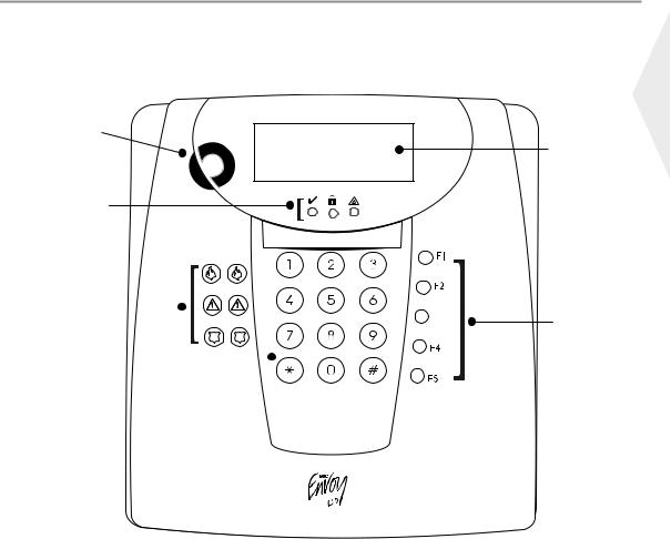
Envoy System Keypad
NT9005-433
Siren |
Liquid |
|
Crystal |
||
|
||
|
Display |
|
|
(LCD) |
Status
Lights
Emergency
Keys 
 Function
Buttons
Number 
Pad
English
3
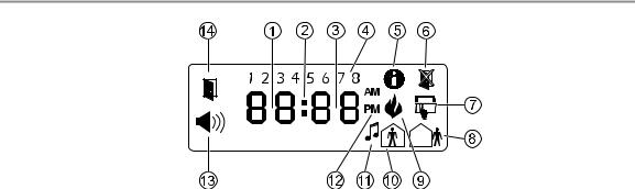
Liquid Crystal Display (LCD)
1Clock Digits 1, 2 – These two 7 segment clock digits indicate the hour digits when the local clock is active, and identify the zone when the OPEN or ALARM icons are active. These two digits scroll one zone per second from the lowest zone number to the highest when scrolling through zones.
2: (Colon) – This icon is the hours/minutes divider and will flash once a second when the local clock is active.
3Clock Digits 3, 4 – These two 7 segment displays are the minute digits when the local clock is active.
41 to 8 – These numbers identify troubles when 
 is pressed.
5Memory – Indicates that there are alarms in memory.
6Bypass – Indicates that there are zones automatically or manually bypassed.
7Program – indicates that the system is in Installer’s Programming, or the keypad is busy.
8Away – Indicates that the panel is armed in the Away Mode. It will turn on at the beginning of the Exit Delay.
9Fire – Indicates that there are fire alarms in memory.
10Stay – Indicates that the panel is armed in the Stay Mode. It will turn on at the beginning of the Exit Delay.
11Chime – This icon turns on when the Chime function key or 
 is pressed to enable Door Chime on the system. It will turn off when the Chime function key or
 is pressed again to disable Door Chime.
12AM, PM – This icon indicates that the local clock is displaying 12 Hr. time. These icons will not be on if the system is programmed for 24 Hr. time.
13ALARM – This icon is used with clock digits 1 and 2 to indicate zones in alarm on the system. When a zone is in alarm, the ALARM icon will turn on, and 7 segment displays 1 and 2 will scroll through the zones in alarm.
14OPEN – This icon is used with clock digits 1 and 2 to indicate violated zones (not alarm) on the system. When zones are opened, the OPEN icon will turn on and 7 segment displays 1 & 2 will scroll through the violated zones.
4

Reference Sheets
Fill out the following information for future reference and store this guide in a safe place.
Access Codes
Master Code [40] : _________________________
Code |
Access Code |
Code |
Access Code |
Code |
Access Code |
Code |
Access Code |
|
|
|
|
|
|
|
|
01 |
|
09 |
|
17 |
|
25 |
|
|
|
|
|
|
|
|
|
02 |
|
10 |
|
18 |
|
26 |
|
|
|
|
|
|
|
|
|
03 |
|
11 |
|
19 |
|
27 |
|
|
|
|
|
|
|
|
|
04 |
|
12 |
|
20 |
|
28 |
|
|
|
|
|
|
|
|
|
05 |
|
13 |
|
21 |
|
29 |
|
|
|
|
|
|
|
|
|
06 |
|
14 |
|
22 |
|
30 |
|
|
|
|
|
|
|
|
|
07 |
|
15 |
|
23 |
|
31 |
|
|
|
|
|
|
|
|
|
08 |
|
16 |
|
24 |
|
32 |
|
|
|
|
|
|
|
|
|
Sensor /Zone Information
Enabled?
FIRE |
AUXILIARY PANIC |
The Exit Delay Time is _______ seconds.


 The Entry Delay Time is _______ seconds.
English
5
Sensor |
Protected Area |
Sensor Type |
Sensor |
Protected Area |
Sensor Type |
|
|
|
|
|
|
01 |
|
|
33 |
|
|
|
|
|
|
|
|
02 |
|
|
34 |
|
|
|
|
|
|
|
|
03 |
|
|
35 |
|
|
|
|
|
|
|
|
04 |
|
|
36 |
|
|
|
|
|
|
|
|
05 |
|
|
37 |
|
|
|
|
|
|
|
|
06 |
|
|
38 |
|
|
|
|
|
|
|
|
07 |
|
|
39 |
|
|
|
|
|
|
|
|
08 |
|
|
40 |
|
|
|
|
|
|
|
|
09 |
|
|
41 |
|
|
|
|
|
|
|
|
10 |
|
|
42 |
|
|
|
|
|
|
|
|
11 |
|
|
43 |
|
|
|
|
|
|
|
|
12 |
|
|
44 |
|
|
|
|
|
|
|
|
13 |
|
|
45 |
|
|
|
|
|
|
|
|
14 |
|
|
46 |
|
|
|
|
|
|
|
|
15 |
|
|
47 |
|
|
|
|
|
|
|
|
16 |
|
|
48 |
|
|
|
|
|
|
|
|
17 |
|
|
49 |
|
|
|
|
|
|
|
|
18 |
|
|
50 |
|
|
|
|
|
|
|
|
19 |
|
|
51 |
|
|
|
|
|
|
|
|
20 |
|
|
52 |
|
|
|
|
|
|
|
|
21 |
|
|
53 |
|
|
|
|
|
|
|
|
22 |
|
|
54 |
|
|
|
|
|
|
|
|
23 |
|
|
55 |
|
|
|
|
|
|
|
|
24 |
|
|
56 |
|
|
|
|
|
|
|
|
25 |
|
|
57 |
|
|
|
|
|
|
|
|
26 |
|
|
58 |
|
|
|
|
|
|
|
|
27 |
|
|
59 |
|
|
|
|
|
|
|
|
28 |
|
|
60 |
|
|
|
|
|
|
|
|
29 |
|
|
61 |
|
|
|
|
|
|
|
|
30 |
|
|
62 |
|
|
|
|
|
|
|
|
31 |
|
|
63 |
|
|
|
|
|
|
|
|
32 |
|
|
64 |
|
|
|
|
|
|
|
|
6

About Your Security System
Your DSC Security System has been designed to provide you with the greatest possible flexibility and convenience. Read this manual carefully and have your installer instruct you on your system's operation and on which features have been implemented in your system. All users of this system should be equally instructed in its use. Fill out the “System Information” page with all of you zone information and access codes and store this manual in a safe place for future reference.
Fire Detection
This equipment is capable of monitoring fire detection devices such as smoke detectors and providing a warning if a fire condition is detected. Good fire detection depends on having adequate number of detectors placed in appropriate locations. This equipment should be installed in accordance with NFPA 72 (N.F.P.A., Batterymarch Park, Quincey MA 02269). Carefully review the Family Escape Planning guidelines in this manual.
NOTE: Your installer must enable the fire detection portion of this equipment before it becomes functional.
Testing
To insure that your system continues to function as intended, you must test your system weekly. Please refer to the “System Test” section in this manual. If your system does not function properly, call your installing company for service.
Monitoring
This system is capable of transmitting alarms, troubles and emergency information over telephone lines to a central station. If you inadvertently initiate an alarm, immediately call the central station to prevent an unnecessary response.
NOTE: The monitoring function must be enabled by the installer before it becomes functional.
General System Operation
Your security system is made up of a DSC control panel, one or more keypads and various sensors and detectors. The control panel will be mounted out of the way in a utility closet or in a basement. The metal cabinet contains the system electronics, fuses and stand-by battery. There is normally no reason for anyone but the installer or service professional to have access to the control panel.
All the keypads have an audible indicator and command entry keys. The LED keypads have a group of zone and system status lights. The LCD keypad has an alphanumeric liquid crystal display (LCD).
The keypad is used to send commands to the system and to display the current system status. The keypad(s) will be mounted in a convenient location inside the protected premises close to the entry/exit door(s).
The security system has several zones of area protection and each of these zones will be connected to one or more sensors (motion detectors, glassbreak detectors, door contacts, etc.). A sensor in alarm will be indicated by the corresponding zone lights flashing on a LED keypad or by written messages on the LCD keypad.
IMPORTANT NOTICE
A security system cannot prevent emergencies. It is only intended to alert you and – if included – your central station of an emergency situation. Security systems are generally very reliable but they may not work under all conditions and they are not a substitute for prudent security practices or life and property insurance. Your security system should be installed and serviced by qualified security professionals who should instruct you on the level of protection that has been provided and on system operations.
English
7

Arming (Turning On/Setting)
Close all sensors (i.e. stop motion and close doors). The Ready ( ) indicator should be on.
To arm, press and hold the Away key for 2 seconds and/or enter your Access Code. The Armed ( ) indicator will turn on, and the keypad will beep. You now have ____ seconds to leave the premises. To cancel the arming sequence, enter your access code.
Arming Error
An error tone will sound if the system is unable to arm. This will happen if the system is not ready to arm (i.e. sensors are open), or if an incorrect user code has been entered. If this happens, ensure all sensors are secure, press  and try again.
Disarming (Turning Off /Unsetting)
Enter your access code to disarm anytime the system is armed (i.e. Armed ( ) indicator is on).
The keypad will beep if you walk through the entry door. You must enter your code within ___ seconds to avoid an alarm condition.
Disarming Error
If your code is not valid, the system will not disarm and a 2-second error tone will sound. If this happens, press  and try again.
Stay Arming (Partially On / Part Set)
Stay arming will bypass the interior protection (i.e. motion sensors) and arm the perimeter of the system (i.e. doors and windows). Close all sensors (i.e. stop motion and close doors). The Ready ( ) indicator should be on. Ask your alarm company if this function is available on your system.
Press and hold the Stay key for 2 seconds, and/or enter your Access Code, and do not leave the premises.
The Armed ( ) indicator and Bypass or System indicator will turn on. The system will automatically bypass certain interior sensors (i.e. motion sensors).
Emergency Keys
The Fire, Auxiliary and Panic Emergency keys will NOT function unless programmed and enabled by the installer.
Press the  ,
,  or
or  key for 2 seconds to generate a Fire, Auxiliary or Panic alarm. Ask your alarm company if the emergency keys are available on your system.
When Alarm Sounds
The system can generate 2 different alarm sounds:
Continuous Siren = Instrusion (Burglary Alarm)
Temporal / Pulsed Siren = Fire Alarm
Intrusion (Burglar) Alarm Continuous Siren
 If you are unsure of the source of the alarm, approach with caution !
If the alarm was accidental, enter your Access Code to silence the alarm. Call your central station to avoid a dispatch.
8
Fire Alarm Pulsed Siren
 Follow your emergency evacuation plan immediately!
If the fire alarm was accidental (i.e. burned toast, bathroom steam, etc.), enter your Access Code to silence the alarm. Call your central station to avoid a dispatch. Ask your alarm company if your system has been equipped with fire detection.
To reset the detectors, see the Sensor Reset section below.
Alarm Memory
When an alarm occurs, the Memory or System indicator (and Fire indicator, if applicable) will turn on.
To view which sensor(s) generated the alarm, press 
 . The Memory or System indicator and corresponding sensor number will flash (i.e. sensor 3).
For the LCD5500 keypad use the 

 scroll keys to view the sensors in alarm memory. Press
  to exit. To clear the memory, arm and disarm the system.
If an alarm sounded while armed, the keypad will automatically go to alarm memory when you disarm the system. In this instance, you should approach with caution, as the intruder may still be within the building/premises.
English
Sensor Reset
Certain sensors, after having detected an alarm condition, require a reset to exit the alarm condition (i.e. glass break sensors, smoke detectors, etc.). Ask your alarm company if this function is required on your system.
To reset the detectors, press and hold the Reset key for 2 seconds or press 

 .
.
If a sensor fails to reset, it may still be detecting an alarm condition. If the sensor reset is successful, the alarm is cancelled. If unsuccessful, the alarm will reactivate or continue.
System Test (Keypad, Siren and Battery)
If you are going to perform a System Test, call your Monitoring Station to inform them when you begin and also when you end the test.
Press 
 , plus your Master Access Code. The Program or System indicator will flash and the Armed (
 ) indicator will turn on.
Press  to initiate the 2-second test (siren and keypad will activate). Press
  to exit.
Access Code Programming
In addition to the Master Access Code, you can program up to 32 additional User Access codes. Press 
 , plus your Master Access Code. The Program or System indicator will begin to flash, and the Armed (
 ) indicator will turn on.
Enter the 2-digit number to programmed (i.e. 06 for user access code 6; enter 40 for the Master Access Code). The Ready ( ) indicator will turn on.
When using the LCD5500, use the 

 scroll keys to find the specific code and press
  to select. Enter the new 4-digit access code, or press
  to erase it. When programming is complete, enter another 2-digit code to program or press
  to exit.
For systems using multiple partitions/areas, access codes can be assigned to specific or multiple partitions/areas. Please contact your alarm company for details.
9

Time & Date Programming
Press 
 , plus your Master Access Code. The Program or System indicator will begin to flash, and the Armed (
 ) indicator will turn on.
Press  to select Time and Date. The Ready (
 ) indicator will turn on.
When using the LCD5500, use the 
 scroll keys to find the menu option and press
  to select.
Enter the time in 24-hr format (HH:MM), followed by the date (MM:DD:YY). Press  to exit programming.
Quick Exit
If the system is armed and you need to exit, use the Quick Exit function to avoid disarming and rearming the system. Press and hold the Exit key for 2 seconds or press 
 . You now have 2 minutes to leave the premises through your exit door. When the door is closed again, the remaining exit time is cancelled.
Door Chime (Entry/Exit Beeps)
To turn the door chime function on or off, press and hold the Chime key for 2 seconds or press 
 .
.
Trouble Conditions
When a trouble condition is detected, the Trouble ( ) or System indicator will turn on, and the keypad will beep every 10 seconds. Press the
  key to silence the beeps. Press
 to view the trouble condition. The Trouble (
 ) or System indicator will flash. The corresponding trouble will be represented by numbers 1-8.
LED/ |
Trouble Condition |
Comments |
Action |
|
DIGIT |
||||
|
|
|
||
|
|
|
|
|
1 |
Service Required |
|
Call for service |
|
|
|
|
|
|
2 |
Loss of AC Power |
If the building and/or neighborhood has lost electrical power, the |
Call for service |
|
system will continue to operate on battery for several hours. |
||||
|
|
|
||
|
|
|
|
|
3 |
Telephone Line Fault |
The system has detected that the telephone line is cut. |
Call for service |
|
|
|
|
|
|
4 |
Failure to Communicate |
The system attempted to communicate with the monitoring sta- |
Call for service |
|
tion, but failed. This may be due to Trouble 3. |
||||
|
|
|
||
|
|
|
|
|
5 |
Sensor (or Zone) Fault |
The system is experiencing difficulties with one or more sensors |
Call for service |
|
on the system. |
||||
|
|
|
||
|
|
|
|
|
6 |
Sensor (or Zone) Tamper |
The system has detected a tamper condition with one or more |
Call for service |
|
sensors on the system. |
||||
|
|
|
||
|
|
|
|
|
7 |
Sensor (or Zone) Low Battery |
If the system has been equipped with wireless sensors, one or |
Call for service |
|
more has reported a low battery condition. |
||||
|
|
|
||
|
|
|
|
|
8 |
Loss of Time & Date |
If complete power was lost (AC and Battery), the time and date |
Call for service |
|
will need to be re-programmed. |
||||
|
|
|
||
|
|
|
|
Bypassing
To bypass a sensor, press 
 . The bypass or system indicator will flash.
Enter the 2-digit number for the sensor to be bypassed (i.e. 03 for sensor number 3). To bypass an additional sensor, enter another 2-digit entry for that sensor. Press  to exit. The bypass or system indicator will stay on.
For the LCD5500, use the 

 scroll keys to find the specific sensor and press
  to bypass.
10
 Loading...