


PC1616/PC1832/PC1864 STANDARD INSTALLATION GUIDE
This Installation Guide provides the basic installation, wiring and programming information required to program the PowerSeries PC1616, PC1832 and PC1864 control panels. This guide shall be used in conjunction with the PowerSeries PC1616/1832/1864 Reference Manual which can be obtained from your local dealer or downloaded from the DSC web site at www.dsc.com.
NOTE: All necessary information required to meet UL Listing requirements is contained in this document.
Read the complete guide, then work through each step as indicated.
OUT Of THE BOX
Qty 1 |
Cabinet |
|
Qty 1 |
PC Module |
|
Qty 1 |
Installation guide |
|
Qty 1 |
User manual |
|
Qty 2 |
Cabinet Label |
|
Qty 1 |
Cabinet Door Plug |
|
Qty 4 |
|
Standoffs |
Qty 16 |
|
5.6KΩ Resistors |
Qty 1 |
2.2KΩ Resistors |
|
Qty 1 |
1.0KΩ Resistors |
|
Qty 1 |
|
10Ω Resistors |
Qty 1 |
|
Grounding Kit |
SPECIFICATIONS
Temp Range ....... |
0°C-49°C (32°F-120°F) |
|
Humidity (Max)........................... |
|
93%R.H. |
Power Supply........ |
16.5VAC/40VA @60Hz |
|
Current Draw (Panel) ......... |
110mA (nom.) |
|
Aux+ Output............ |
11.1-12.6VDC/700mA |
|
Bell Output.............. |
11.1-12.6VDC/700mA |
|
FEATURES |
PC1616 |
PC1832 |
PC1864 |
|
|
|
|
On-board Zones |
6 |
8 |
8 |
|
|
|
|
Hardwired Zones |
16 (1xPC5108) |
32(3xPC5108) |
64 (7xPC5108) |
|
|
|
|
Wireless Zones |
16 |
32 |
32 |
|
|
|
|
Keypad Zone Support |
|
|
|
|
|
|
|
On-board PGM Outputs |
PGM 1 - 50mA |
PGM 1 - 50mA |
PGM 1, 3, 4 - 50mA |
|
PGM 2 - 300mA |
PGM 2 - 300mA |
PGM 2 - 300mA |
|
|
|
|
PGM Expansion |
8x50mA (PC5208) |
8x50mA (PC5208) |
8x50mA (PC5208) |
|
4x500 mA (PC5204) |
4x500 mA (PC5204) |
4x500 mA (PC5204) |
|
|
|
|
Keypads |
8 |
8 |
8 |
|
|
|
|
Partitions |
2 |
4 |
8 |
|
|
|
|
User Codes |
32 + Master Codes |
32 + Master Codes |
32 + Master Codes |
|
|
|
|
Event Buffer |
500 Events |
500 Events |
500 Events |
|
|
|
|
Transformer Required |
16.5VAC/40VA |
16.5VAC/40VA |
16.5VAC/40VA |
|
|
|
|
Battery Required |
4Ah / 7Ah/14AHr |
4Ah / 7Ah/14AHr |
4Ah / 7Ah/14AHr |
|
|
|
|
Bell Output |
12V/700 mA (cont) |
12V/700 mA (cont) |
12V/700 mA (cont) |
|
|
|
|
COMPATIBLE DEVICES
Keypads (Backward compatible with all PowerSeries keypads)
PK5500 Keypad........................................................... |
|
125mA (max.) |
PK5501 Keypad........................................................... |
|
125mA (max.) |
PK5508 LED Keypad................................................... |
|
125mA (max.) |
PK5516 LED Keypad................................................... |
|
125mA (max.) |
PC5532Z LED Keypad ................................................ |
|
125mA (max.) |
LCD5511 Fixed Message LCD Keypad........................ |
85mA (max.) |
|
LED5511Z 8-zone LED Keypad ................................. |
|
100mA (max.) |
Cabinets |
|
|
PC5003C ..................................... |
222x298x78mm (11.3x11.7x3.0in) |
|
PC500C ......................................... |
213x235x78mm (8.4x9.25x3.0in) |
|
Refer to the Reference Manual for alternate control cabinets
Modules
T-Link TL-250/TL300 ....................................................... |
|
275/350mA |
PC5100 2-wire Interface ............ |
40mA plus devices to 170mA max. |
|
PC5132-433 Wireless Receiver ............................................. |
|
125mA |
RF5108-433 Wireless Receiver ............................................. |
|
125mA |
PC5108 Zone Expander .......................................................... |
|
30mA |
PC5204 Power Supply with 4 Programmable Outputs |
............30mA |
|
PC5208 Low Current Programmable Output Module .............. |
50mA |
|
PC5400 Printer/DVAC Module ................................................. |
|
65mA |
PC5401 Bi-Directional RS232 Module (Not UL Listed) ............ |
65mA |
|
Escort5580 Telephone Interface Module ............................... |
130mA |
|
Refer to the Reference Manual for additional devices.
Classified in Accordance with ANSI/SIA CP-01-2000 (SIA-FAR)
2 9 0 0 7 1 0 9 R0 0 3
Hardware Installation
Begin the installation by mounting the cabinet in a dry protected area with access to unswitched AC power. Install Hardware in the sequence indicated below. Do NOT apply power until installation is complete.
NOTE: All wiring entry points are designated by arrows. All circuits are classified UL power limited except for the battery leads. Minimum 1/4” (6.4mm) separation must be maintained at all points between power limited and non-power limited wiring and connections.
1. Keybus Wiring
The 4-wire KEYBUS (red, black, yellow and green) is the communication connection between the control panel and all modules. The 4 KEYBUS terminals of all modules must be connected to the 4 KEYBUS terminals of the main control panel.
The following rules must be followed when wiring the Keybus:
•Minimum 22 AWG wire, maximum 18 AWG (2-wire twisted preferred
•Do NOT use shielded wire
•Modules can be home run, connected in series or can be T- tapped provided that the maximum wire distance from the control panel to any module does not exceed 1,000 feet (305m)
•No more than 3,000 feet (915m) of wire can be used in total
150’ (46m) |
|
150’ (46m) |
500’ (152m) |
CONTROL
PANEL 500’ (152m)
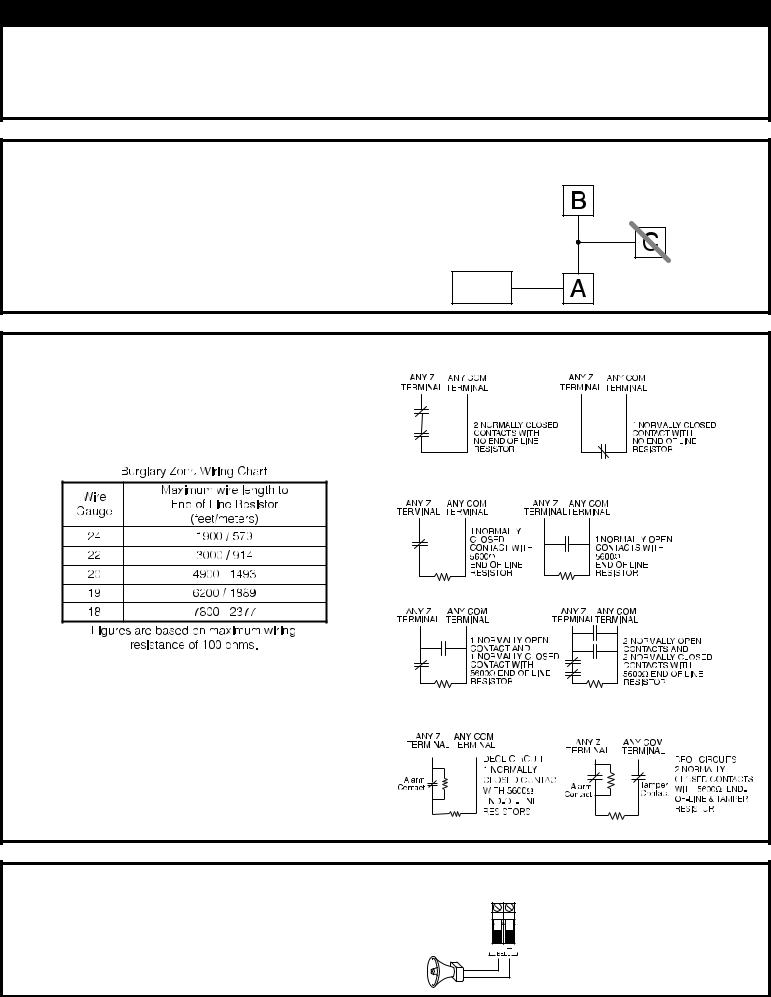
2. Zone Wiring
Zones can be wired for Normally Open, Normally Closed Contacts
with Single-end-of-line (SEOL) resistors or Double End-of-Line Normally Closed Loops - Do NOT use for UL Installations (DEOL) resistors. Observe the following guidelines
• For UL Listed Installations use SEOL or DEOL only.
•Minimum 22 AWG wire, maximum 18 AWG
•Do NOT use shielded wire
• Wire run resistance shall not exceed 100Ω. Refer to the chart below.
Single End-of-Line Resistor Wiring
• Section [001-004] Selects Zone Definition
• Section [013] Opt [1] Selects Normally Closed or EOL resistors
• Section [013] Opt [2] Selects Single EOL or Double EOL resis-
tors. |
|
Double End-of-Line Resistor Wiring |
||||||||||||
|
|
|||||||||||||
Zone Status |
|
|
|
|
|
|
|
|
|
|
|
|
|
|
|
|
|
|
|
|
|
|
|
|
|
|
|
|
|
|
|
|
|
|
|
|
|
|
|
|
|
|
|
|
|
|
|
|
|
|
|
|
|
|
|
|
|
|
|
|
|
|
|
|
|
|
|
|
|
|
|
|
|
|
Loop Resistance |
Loop Status |
|||||||||||||
- 0Ω (shorted wire/loop) |
Fault |
|
|
|
|
|
|
|
|
|
|
|||
|
|
|
|
|
|
|
|
|
|
|
|
|
||
- 5600Ω (contact closed) |
Secure |
|
|
|||||||||||
|
||||||||||||||
|
||||||||||||||
- infinite (broken wire, open) |
Tamper |
|
|
|||||||||||
|
||||||||||||||
- 11,200Ω (contact open) |
Violated |
|||||||||||||
3. Bell Wiring
These terminals supply 700mA of current at 12VDC for commercial installations and 11.1-12.6 VDC for residential installations (e.g.DSC SD-15 WULF). To comply with NFPA 72 Temporal Three Pattern requirements:
Program Section [013] Opt [8] ON.
The Bell output is supervised and power limited. If unused, connect a 1000Ω resistor across Bell+ and Bellto prevent the panel from displaying a trouble. See [ ][2].
BELL/SIREN 700mA (max.)
OBSERVE
POLARITY
NOTE: Bell output is current limited by 2A PTC
NOTE: Steady, Pulsed and Temporal Three Pattern alarms are supported.

Hardware Installation (Cont.)
North America Only
1.Insert Stand off into cabinet mounting hole in the desired location. Snap-in- place.
2.Position circuit board mounting holes over standoffs. Press firmly
on board to snap-in-place.
PC Board
Cabinet
Stand Off
Primary:120VAC/60Hz.
Secondary: 16.5VDC 40VA
DSCPTD 1640U
Class II Transformer
NOTE: Do not connect transformer to receptacle controlled by a switch
230 VAC/50 Hz International
CON1
BAT+BAT-
AC AC
To EGND
Terminal
16.5VAC/40VA
FUSE
IMPORTANT:
a)This equipment, Alarm Controller PC1616/1832/1864 shall be installed and used within an environment that provides the pollution degree max 2 and overvoltages category II
NON-HAZARDOUS LOCATIONS, indoor only. The equipment is FIXED and PERMANENTLY connected and is designed to be installed by service persons only; [service person is defined as a person having the appropriate technical training and experience necessary to be aware of hazards to which that person may be exposed in performing a task and of measures to minimize the risks to that person or other persons.]
b)The connection to the mains supply must be made as per the local authorities rules and regulations.
An appropriate disconnect device must be provided as part of the building installation. Where it is not possible to rely on identification of the neutral in the AC Mains supply the disconnecting device must disconnect both poles simultaneously (line and neutral). The device shall disconnect the supply during servicing.
c)The equipment enclosure must be secured to the building structure before operation.
POWER LIMITED
Cable Tie (not supplied) recommended
|
UA503 |
DSC |
220 |
PC1616/1832/1864 |
|
WARNING:
High Voltage. Disconnect AC Power and telephone lines before servicing
PC1864 |
PC1864 |
Only |
PC1832 |
CON1 |
Only |
BAT+BAT- |
TB-2 |
|
AUX+ |
BELL+ |
PGM1 PGM3 |
EGND |
RING |
R-1 |
AC AC |
|
AUXBELLRED BLK YEL GRN |
PGM2 PGM4 Z1 COM Z2 Z3 COM Z4 Z5 COM Z6 Z7 COM Z8 |
TIP |
T-1 |
|
See Section 9 |
|
|
for ground wiring details |
|
|
12V / 7 AHr |
12V / 7 AHr |
|
BLACK |
|
|
RED |
|
NON-POWER LIMITED |
DSC Model BD7-12 |
|
or equivalent |
|
|
|
|
|
|
Battery |
|
|
StandbyTime: |
|
|
24Hrs min. |
|
WARNING: Incorrect connections may result in PTC failure or improper operation. Inspect wiring and ensure connections are correct before applying power.
Incorrect connection of batteries may result in battery rupture or Fire Hazard. Do NOT allow metal objects to connect the Positive and Negative Terminals. Ensure that batteries are connected with correct polarity (Red to (+), Black to (-)). Failure to comply with this may result in battery rupture and/or Fire Hazard.
All circuits are classified for UL Installations as Power Limited/Class II Power Limited except for battery leads which are not power limited.
Do NOT route any wiring over circuit boards. Maintain at least 1"(25.4mm) separation. A minimum of 1/4" (6.4mm) separation must be maintained at all points between power limited wiring and all other non-power limited wiring.
UA503 |
REV XX |
DSC |
|
|
220 |
PC1616/1832/1864 |
|
|
|
|
|
|
PC-LINK |
AUX+ and Keybus (Red) are Internally Connected |
10 |
|
Total current draw from Keypads, PGM Outputs and |
||
Aux circuits must not exceed 550ma
e)Internal wiring must be routed in a manner that prevents:
-Excessive strain on wire and on terminal connections;
-Loosening of terminal; connections;
-Damage of conductor insulation
f)Disposal of the used batteries shall be made according to the waste recovery and recycling regulations applicable to the intended market.
g)Before servicing, DISCONNECT the telephone connection.
|
Internally Connected |
|
PC1864 |
PC1864 |
|
Only |
PC1832 |
|
CON1 |
Only |
|
TB-2 |
||
BAT+BAT- |
||
|
|
|
AUX+ BELL+ |
PGM1 PGM3 |
EGND |
RING |
R-1 |
|||||||||||
AC AC |
|
AUXBELL- RED BLK YEL GRN |
|
PGM2 PGM4 Z1 COM Z2 Z3 COM Z4 Z5 COM Z6 Z7 COM Z8 |
TIP |
T-1 |
|||||||||||
|
|
|
|
|
|
|
|
|
|
|
|
|
|
|
|
|
|
WARNING: |
8 |
9 |
4 |
3 |
1 |
5 |
2 |
7 |
6 |
|
|
|
|
|
|
|
|
|
High Voltage. Disconnect AC Power and telephone lines before servicing
See corresponding Section NumberText for wiring details.

Hardware Installation (Cont.)
4. AUX Power Wiring
The control panel can provide a maximum of 700mA of current for modules, powered detectors, relays, LED’s etc.… If the total current required exceeds 700mA an additional power supply is required (e.g.,PC5200, PC5204). See list below.
NOTE: Min/max operating voltages for devices, sensors and modules is 9.5VDC - 14VDC
Refer to the list of Compatible Devices on the first page for the current draw of individual devices
5. PGM Wiring
PGMs switch to ground when activated by control panel.
Connect the positive side of the device to be activated to the AUX+ Terminal. Connect the negative terminal to the PGM.
current output is as follows
• |
PGM 1, 3, 4 |
.................... 50mA |
• |
PGM 2 .......................... |
300mA |
For currents levels greater than 300mA a relay is required. PGM2 can also be used for 2-wire smoke detectors.
NOTE: Use SEOL resistors on Fire Zones ONLY.
2-wire Smoke Detectors Initiating Circuit
•Style B (Class B), Supervised, Power Limited
• |
Compatibility Identifier ........................................................ |
PC18-1 |
• |
DC Output Voltage..................................................... |
9.8-13.8 VDC |
• |
Detector Load ............................................................. |
2 mA (MAX) |
• |
Single-end-of-line (SEOL) Resistor ..................................... |
2200Ω |
• |
Loop Resistance............................................................ |
24Ω (MAX) |
• |
Standby Impedance.................................................. |
1020Ω (ΝΟΜ) |
• |
Alarm Impedance ........................................................ |
570Ω (MAX) |
• |
Alarm Current ............................................................ |
89 mA (MAX) |
PGM 1, LED Output with current limiting resistor and Optional Relay driver output
Compatibility ID For FSA-210B Series is: FS200 |
4-wire Smoke Detectors |
RM-1/RM-2 POWER LOOP
SUPERVISORY RELAY
6. Telephone Line Wiring
Wire the telephone connection terminals (TIP, Ring, T-1, R-1) to an RJ-31x Connector as indicated.
For connection of multiple devices to the telephone line, wire in the sequence indicated.
Telephone format is programmed in section [350].
Telephone Call Directions are programmed in section [351]-[376].
T-1

 R-1
R-1 

TIP

RING |
RJ-31X |
7. Ground |
8.Battery |
9. AC Wiring |
Ground Installation
Tighten nut to break paint and make good connection to the cabinet
A sealed, rechargeable, lead acid battery or gel type battery is required to meet UL requirements for power standby times. NOTE: UL Residential/Commercial Burglary installations require 4Hrs Power Standby time. NOTE: UL/ULC Residential Fire & Home Care installations require 24 Hr power standby. ULC Commercial Burglary
and Fire monitoring installations require 24 Hr power standby.
Standby Battery Guide |
AC Wiring |
||
Battery Charging Current: 400 mA |
|
||
|
|
|
UL Listed Installations |
Batt |
Standby |
Primary: 120VAC/60Hz./0.33A |
|
Size |
4Hr |
24Hr |
Secondary: 16.5VAC/40VA |
------------------------------------------------- |
|
|
DSCPTD 1640 Plug-in, Class 2 |
4Ahr |
700mA |
---- |
Transformer. |
7Ahr |
700mA |
180mA |
|
14Ahr |
700mA |
470mA |
NOTE: Do not connect trans- |
|
NOTE: |
|
former to a receptacle controlled |
|
|
by a switch. (UL Listed Installations |
|
Replace batteries every 3-5 years. |
Only) |
||
|
|||
Battery capacity will deteriorate with |
|
||
age and number of charge/discharge |
|
||
cycles |
|
|
|
|
|
|
|

TESTING & TROUBLESHOOTING
Testing:
•Power up system
•Program options as required (See Programming Section on reverse side)
Note: For advanced programming refer to the PC1616/1832/1864 Reference manual
•Violate, then restore zones
•Verify correct Reporting Codes are sent to the Central Station
Troubleshooting:
LCD5500 LCD Programmable-Message Keypad
•Press [ ][2] to view a trouble condition.
•The trouble light will flash and the LCD will display the first trouble condition present.
•Use the arrow keys to scroll through all trouble conditions present.
NOTE: When additional information is available for a specific trouble condition a [ ] will appear on the display. Press the [ ] key to view the additional information
LED Keypads, LCD Fixed Message Keypads
•Press [ ][2] to view a trouble condition.
•The trouble light will flash.
•Refer to the Trouble Summary chart below to determine the trouble condition(s) present.
Trouble Summary:
Light [1] Service Required - Press [1] for more information
[1]Low Battery
[2]Bell Circuit
[3]General System Trouble
[4]General system Tamper
[5]Module Supervision
[6]RF Jam Detected
[7]PC5204 Low Battery
[8]PC5204 AC Failure
Light [2] AC Trouble
Light [3] Telephone Line Trouble
Light [4] Failure to Communicate
Light [5] Zone Fault -Press [5] for more information
Light [6] Zone Tamper - Press [6] for more information
Light [7] Wireless Device Low Battery - Press [7] for more information
Light [8] Loss of Time or Date
 Loading...