


 Loading...
TABLE OF CONTENTS
FEATURES |
2 |
SPECIFICATIONS |
2 |
INSTALLATION |
3 |
Mounting the Panel ............................................................... |
3 |
Mounting the Keypad ........................................................... |
3 |
Auxiliary Power Connection .................................................. |
3 |
PGM Terminal Connections .................................................. |
3 |
Bell/Siren Connection ........................................................... |
3 |
Keypad Wiring ...................................................................... |
3 |
Fire Zone Wiring .................................................................... |
3 |
Burglary Zone Wiring ............................................................ |
3 |
Battery Connection ............................................................... |
3 |
Telephone Line Wiring .......................................................... |
3 |
GUIDELINES FOR LOCATING SMOKE DETECTORS |
4 |
KEYPAD FUNCTIONS |
5 |
Introduction ........................................................................... |
5 |
Master Code ......................................................................... |
5 |
2nd Master Code .................................................................. |
5 |
Installer’s Programming Code .............................................. |
5 |
Arming .................................................................................. |
5 |
Auto-Bypass/Home-Away Arming ........................................ |
5 |
Arming Without Entry Delay .................................................. |
5 |
Disarming .............................................................................. |
5 |
Zone Bypassing [ ]+[1] ....................................................... |
5 |
Trouble Conditions [ ]+[2] ................................................... |
5 |
Alarm Memory [ ]+[3] .......................................................... |
6 |
Downloading Callup Command [ ]+[4] ............................... |
6 |
User Programming Commands [ ]+[5] ............................... |
6 |
EEPROM Reset ..................................................................... |
6 |
User Function Commands [ ]+[6]+[Master Code] .............. |
6 |
Utility Output Command |
|
[ ]+[7] or [ ]+[7]+[Access Code] ............................ |
7 |
Installer’s Programming Command |
|
[ ]+[8]+[Installer’s Code] ........................................... |
7 |
Arming without Entry Delay [ ]+[9]+[Access Code] ........... |
7 |
Arming For The Night [ ]+[1] ............................................... |
7 |
Quick-Exit Command [ ]+[0] when armed .......................... |
7 |
Quick-Arm Command [ ]+[0] .............................................. |
7 |
Keypad Zones ...................................................................... |
7 |
PROGRAMMING |
8 |
How to Program .................................................................... |
8 |
Program Data Review ........................................................... |
8 |
Binary Data Display .............................................................. |
8 |
HEX Data Programming ........................................................ |
8 |
Programming Sections ......................................................... |
8 |
[00] Binary Programming ................................................. |
8 |
[01] 1st Phone Number .................................................... |
|
8 |
[02] 1st Account Code ..................................................... |
|
8 |
[03] 2nd Phone Number ................................................... |
|
9 |
[04] 2nd Account Code .................................................... |
|
9 |
[05] to [10] Reporting Codes ........................................... |
|
9 |
[05] Zone Alarm Reporting Codes ................................... |
|
9 |
[06] Zone Restoral Reporting Codes .............................. |
|
9 |
[07] Closing (Arming) Reporting Codes |
|
|
Partial Closing Reporting Code ................................ |
|
9 |
[08] Opening (Disarming) Reporting Codes |
|
|
After Alarm Reporting Code ...................................... |
|
9 |
[09] Priority Alarms and Restorals .................................... |
|
9 |
[10] Maintenance Alarms and Restorals ........................ |
|
10 |
[11] Zone Definitions ...................................................... |
|
10 |
[12] 1st System Option Code ......................................... |
|
11 |
[13] 2nd System Option Code ....................................... |
|
11 |
[14] 3rd System Option Code ........................................ |
|
11 |
[15] Communication Variables ....................................... |
|
11 |
[16] Zone Bypass Mask ................................................. |
|
11 |
[17] System Times .......................................................... |
|
11 |
[18] Auxiliary Delay Loop Entry/Exit Times .................... |
12 |
|
[19] System Clock Times ............................................... |
|
12 |
[20] New Installer’s Code ............................................... |
|
12 |
[21] New Master Code ................................................... |
|
12 |
[22] 2nd Master Code ................................................... |
|
12 |
[23] Communication Formats ........................................ |
|
12 |
[24] Programmable Output Options (PGM Terminal) .... |
13 |
|
[25] Communicator Call Directions ................................ |
|
13 |
[26] Downloading Telephone Number ........................... |
|
13 |
[27] Downloading Access Code .................................... |
|
13 |
[28] Panel Identification Code ........................................ |
|
13 |
[29] Number of Rings Before Answering |
....................... |
13 |
[30] Reset to Factory Default ......................................... |
|
13 |
[31] 4th System Option Code ......................................... |
|
14 |
[32] 5th System Option Code ......................................... |
|
14 |
[33] Answering Machine Double Call Timer .................. |
14 |
|
[34] 6th System Option Code ......................................... |
|
14 |
[35] LINKS1000 Test Reporting Code ........................... |
|
14 |
[36] Keypad Lockout Control ......................................... |
|
14 |
[90] Installer’s Lockout Enable ....................................... |
|
14 |
[91] Installer’s Lockout Disable ...................................... |
|
14 |
FOR THE RECORD |
|
15 |
PROGRAMMING WORK SHEETS |
|
16 |
LIMITED WARRANTY |
inside front cover |
|
INDUSTRY CANADA NOTICE |
inside front cover |
|
CONTROL PANEL WIRING DIAGRAM |
inside back cover |
|
1
Features |
Specifications |
Keypad Programmable
The PC1550 is complete with a default program so that it is operational with a minimum of programming. The control panel is completely programmable from the keypad.
EEPROM Memory
The panel uses EEPROM memory which will retain all program information even if AC and battery power are removed from the panel. The EEPROM memory can be reprogrammed thousands of times.
Static/Lightning Protection
The PC1550 has been carefully designed and tested to provide reliable protection against static and lightning induced transients. Our special “Zap-Trac” circuit board design catches high voltage transients right at the wiring terminals, and transient protection devices are placed in all critical areas to further reduce damaging voltages.
Supervision
•Low or disconnected battery
•Loss of AC power
•Fuse open
•Loss of time on system clock
•Microprocessor “Watchdog” circuit
Operation
•Download / Upload capability
•Programmable auto downloading
•Swinger shutdown
•Transmission delay
•Six access codes
•“Master key” code
•All zones programmable as fire zones
•Programmable test transmission
•Zone bypass from the keypad
•Six zones
•Bell / Siren zone
•Programmable output
•Three dedicated keys (Fire/Auxiliary/Panic)
•Backlit, aesthetically pleasing keypad
PC1550 Control Panel
•Six fully programmable zones
-EOL resistor supervised option
-all zones programmable as fire zones.
-maximum zone loop resistance: 100 ohms
•Bell / Siren outputs: 1 amp
-steady for burglary
-pulsed for fire
•Programmable output: 300 mA 9 programmable options
•Auxiliary power output: 475 mA
•PC1500RK keypad, 3 maximum
•Sealed Battery 12 VDC, 4 Ah minimum
•Transformer: 16 VAC, 40 VA
•Panel dimensions:
-10" high x 8" wide x 3" deep (254 x 208 x 76 mm)
-Surface mount
•Panel colour: light beige
PC1500RK Keypad
•Three keypad activated zones: Fire, Auxiliary, Panic
•Backlit keys
•5 system lights:
Ready, Armed , Memory, Bypass, Trouble
•6 zone lights
•Keypad dimensions:
-4.5" H × 4.5" W × 0.93" D (114 × 114 × 23.6 mm)
-Surface mount
•Keypad colour: mist
2
Installation
Mounting the Panel
Select a dry location close to an unswitched AC source and close to the telephone line connection. Remove the printed circuit board, the mounting hardware and the keypad from the cardboard retainer inside the cabinet. Before attaching the cabinet to the wall, press the four white nylon printed circuit board mounting studs into the cabinet from the back. Once the cabinet is mounted to the wall, pull all the cables into the cabinet and prepare them for connection. Use a meter to test the wiring for opens, shorts and grounds. Press the circuit board onto the white nylon mounting studs. Complete all wiring to the control panel before applying AC power or connecting the battery. Do not plug the transformer into an outlet that is controlled by a switch.
NOTE: See Control Panel Wiring Diagram inside the back cover for more information.
Mounting the Keypad
Keypads should be located close to the designated “Entry-Exit” door(s) and mounted at a height convenient for all users.
NOTE: Complete all wiring to the control panel before applying AC power or connecting the battery.
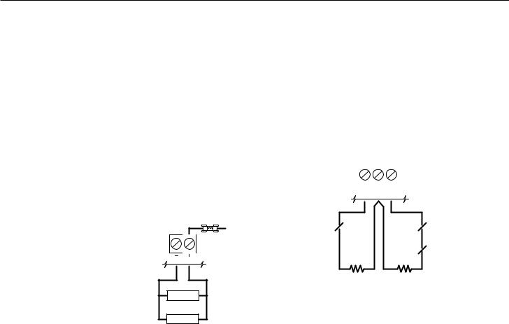
Auxiliary Power Connection
The auxiliary power supply can be used to power keypads, motion detectors and other devices that require 11 VDC. See the Fire Zone Wiring section for the connection of 4-wire smoke detectors. The total load for the auxiliary power output must be calculated for all devices connected across the AUX +/- terminals and for devices connected between the AUX + and PGM terminals. The output current cannot exceed 475 mA. Allow 35 mA for each PC1500RK keypad connected to the panel.
12VDC
FUSE
1 A
AUX
LOAD
LOAD
PGM Terminal Connections
The PGM terminal is a switched negative output which can be controlled by various programming options (See Programming Guide section [24]). Devices controlled by the PGM output must be connected between the PGM terminal, which is (-) and the Aux. (+) terminal.
Bell/Siren Connection
Observe polarity when connecting siren drivers, sirens and polarized bells.
Keypad Wiring
Up to three keypads may be connected in parallel. Do not connect multiple keypads on the same keypad wire run. For Standby Loading purposes, use a current draw of 35 mA per keypad. This represents the panel in the disarmed state with two zones open.
Fire Zone Wiring
Any one of the 6 zones may be programmed as a Fire Loop. See Programming Guide section [11].
Smoke detectors should be the latching type and have Normally Open (N.O.) alarm initiating contacts. Power wiring from the AUX + / PGM terminals should be supervised using an RM-1 relay after the last smoke detector. The RM-1 N.O. contacts (closed with power applied) should be wired in series with the alarm initiating end-of- line resistor so that should power to the detector(s) fail, a fire loop trouble will be initiated.
Burglary Zone Wiring
Burglary zone definition, (eg. Delay, Instant, 24 Hr. etc.) is programmed via the keypad. See the Programming Guide, section [11].
|
|
|
|
|
|
|
|
|
|
|
|
|
|
|
|
|
|
Z1 COM Z2 |
|
||||||
NC |
|
|
|
|
|
|
|
|
|
|
NC |
|
|
|
|
|
|
|
|
|
|
|
|||
EOL RESISTOR |
|
|
|
|
|
|
|
|
|
|
|
EOL RESISTOR |
|
|
|
|
|
|
|
|
|
|
|
||
|
|
|
|
|
|
|
|
|
|
|
||
LOOPS USING |
|
|
|
|
|
|
|
|
|
|
NC |
LOOPS USING |
|
|
NO |
|
|
|
|||||||
NO & NC |
|
|
|
|
|
|
NC DEVICES |
|||||
DEVICES |
|
|
|
|
|
|
|
|
|
|
|
ONLY |
|
END OF LINE |
END OF LINE |
|
|||||||||
|
|
RESISTOR |
RESISTOR |
|
||||||||
|
|
1kΩ 0.5W |
1kΩ 0.5W |
|
||||||||
Battery Connection
If the battery is reverse connected, the 5 A fuse will blow. The battery charging voltage is factory set and normally needs no adjustment. If the battery charging voltage is out of adjustment, contact your service representative.
If AC power is OFF and the battery voltage is approximately 9.5V or lower, the battery will be disconnected and the panel will power down. To power up again, the AC will have to be re-established.
Telephone Line Wiring
NOTE: Ensure that plugs and jacks meet the dimension, tolerance and metallic plating requirements of 47 C.F.R. Part 68, Subpart F.
WARNING
FCC restricts using this equipment on certain types of telephone lines. Also, do not use this equipment on a telephone line equipped with a “call holding” feature, as the tone generated may interfere with the communicator operations.
Do not connect the alarm panel communicator to telephone lines intended for use with facsimile (FAX) machines. These lines may incorporate a voice filter which disconnects the line if other than FAX signals are detected, resulting in incomplete transmissions.
3

Guidelines for Locating Smoke Detectors
Experience has shown that all hostile fires in family living units generate smoke to a greater or lesser extent. Experiments using typical fires in family living units indicate that detectable quantities of smoke precede detectable levels of heat in most cases. For these reasons, smoke detectors should be installed outside of each sleeping area and on each additional story of the family unit.
The following information is for general guidance only and it is recommended that the smoke detector manufacturer's literature be used for detailed installation instructions.
It is recommended that additional smoke detectors beyond those required be installed for increased protection. The added areas include: basement, bedrooms, dining rooms, furnace room, utility room and hallways not protected by the required detectors.
Bedroom |
Bedroom |
|
Bedroom |
Kitchen |
Living Room |
FIG. 1: A smoke detector should be located between the sleeping area and the rest of the family unit.
Bedroom |
Kitchen |
Dining |
|
Room |
|||
|
|
Family Room
Living
Bedroom Room
Bedroom
FIG. 2: In the family living units with more than one sleeping area, a smoke detector should be located to protect each sleeping area.
Bedroom |
Bedroom |
Living |
Dining |
Room |
Room |
Basement |
|
FIG. 3: A smoke detector should be located on each story of the living unit.
4"
(0.1m)
Ceiling
|
4" |
|
Acceptable |
(0.1m) |
|
Max. |
||
here |
||
|
NEVER
HERE 12" (0.3m) Max.
Top of detector acceptable here
Wall
NOTE: Measurements shown are to the closest edge of the detector.
FIG. 4: Smoke Detector mounting - “Dead” Air Space. The smoke from a fire generally rises to the ceiling, spreads out across the ceiling surface and begins to bank down from the ceiling. The corner where the ceiling and wall meet is an air space into which the smoke may have difficulty penetrating. In most fires, this “dead” air space measures about 4 in. (0.1m) along the ceiling from the corner and about 4 in. (0.1m) down the wall as shown in Figure 4. Detectors should not be placed in the dead” air space.
4

Keypad Functions
Introduction
The PC1500RK remote keypad provides complete information and control of the PC1550 control panel. The control panel can be fully programmed from the PC1500RK keypad. The 6 zone lights provide alarm and status indication for the alarm circuits. Each zone can be programmed to be a burglary zone or a fire zone.
Master Code
This code is used to arm and disarm the panel, reset the bells after an alarm, program up to 5 additional codes using the [*][5] command, and to enter other user functions using the [*][6] command. The panel default program allows the user to change the Master Code. The installer can program the panel so that the user cannot change the Master Code. The default Master Code is “1234”. See [13] 2nd System Option Code.
2nd Master Code
A second Master Code can also be programmed. This code can be changed by the installer only, and is useful where there are multiple panels in a complex. The 2nd Master Code may be used as a “Master Key”. The default 2nd Master Code is blank.
Installer’s Programming Code
The default Installer’s Programming Code is “1500”. Using this code and the [*][8] command, the installer can gain access to the system to enter panel program information. This code can be changed by the installer.
Arming
Before arming the panel, close all protected doors and windows and stop movement in areas covered by motion detectors. If the “Trouble” light is on, check for the type of trouble ([*][2]) and correct the fault condition. If the “Bypass” light is on, make sure that bypassed zones are bypassed intentionally, ([*][1]). If the “Ready” light is OFF, one or more zones are open. The system can only be armed when the “Ready” light is ON. To arm, enter a 4 digit access code. As each digit is entered, the keypad sounder will beep. When the correct access code has been entered the “Armed” light will come ON and the keypad will beep 6 times. If the access code has been entered incorrectly, the keypad will sound one long tone. Press the [#] key and enter the access code again.
Once the panel has been armed, exit through the designated entry/ exit door before the exit delay time expires. At the end of the exit delay, all lights on the keypad will go out except the “Armed” light. If the Show Bypassed Status While Armed function has been enabled (section [31], option [4]), the “Bypass” light will be ON if a zone has been bypassed.
See [17] System Times for instructions on changing the Exit Delay time.
Auto-Bypass/Home-Away Arming
Interior zones can be programmed as “Home-Away” zones (section [11]). This means that when a correct access code is entered, and you do not exit the premises, the system will, at the end of the exit delay time, arm with interior zones automatically bypassed. The “Bypass” light will come ON. This is a convenience feature for users who wish to remain at home with the system armed.
Toreactivatetheinteriorzonesthathavebeenautomaticallybypassed, press [*][1]. The “Bypass” light will go out. If the bypassed zones were programmed as Home-Away with delay, the “Bypass” light will go out after the delay. This command is a quick method of fully arming the system before going to bed and is useful for users who have a keypad outside areas protected by the interior zones.
Arming Without Entry Delay
To eliminate Entry Delay, arm the system using [*][9][access code]. An exit may be made as in normal arming. The system will arm as described in Auto-Bypass / Home-Away arming whether an
exit is made or not. The “Armed” light will flash to indicate that the system is armed without an entry delay.
Disarming
Enter the premises through the designated entry-exit door. The keypad sounder will be on as a reminder to disarm the system. Go to the keypad and enter a valid access code. If an error is made entering the code, press [#] and enter the correct code. The “Armed” light will go out and the sounder will stop. A correct access code must be entered before the entry delay expires or the panel will go into alarm. To change the entry delay time see section [17] System Times.
If an alarm occurred while the panel was armed, upon disarming the “Memory” light and the zone light(s) of the zone(s) that caused the alarm will flash for two minutes. Pressing [#] will stop the flashing, extinguish the zone light(s) and return the panel to the ready mode. The “Memory” light will stay on steadily to indicate that an alarm did occur during the last armed period. To view the zone(s) that caused the alarm, see Alarm Memory Display [*][3].
Zone Bypassing
[*]+[1]
A bypassed zone will not be armed and will not sound an alarm. Use zone bypassing when access is needed to part of a protected area or if damage to contacts or wiring cannot be repaired immediately. The panel can be armed with one or more zones bypassed even if the zone(s) are open. The “Ready” light will be ON and the “Bypass” light will be ON if a zone is bypassed. A fire zone cannot be bypassed.
Zone bypasses are automatically cancelled when the panel is disarmed.
To Bypass Zones:
Enter [*][1] - the “Bypass” light will start flashing.
Enter [zone number to be bypassed]; the zone light will come ON to indicate that the zone is bypassed. To remove a bypass, enter the zone number and the zone light will go OFF. Continue entering the zone numbers of the zones you want bypassed. Press [#] to return to Ready.
To Recall Bypassed Zones:
Enter [*][1][9]
This command will recall the last zone or group of zones that were bypassed. This feature is useful if the same group of zones is bypassed regularly.
Bypass Disable:
The installer can program the panel to prevent the user from being able to bypass certain zones. Lights for these zones will not come ON in response to the bypass command. See Zone Bypass Mask (section [16]).
Trouble Conditions
[*]+[2]
The PC1550 continuously monitors a number of trouble conditions. If one of these conditions occurs, the keypad “Trouble” light will come ON and the buzzer will sound two short beeps every 10 seconds. To silence the buzzer, press [#]. The buzzer will stop but the “Trouble” light will remain ON until the trouble condition is cleared.
To view the trouble condition, press [*][2].
1.Low Battery. If the battery voltage is low, the battery is disconnected or the battery fuse is blown, a trouble will be displayed and can be reported.
2.AC Failure. On loss of AC power, the “Trouble” light will come ON immediately, but the keypad buzzer will not sound. The keypad buzzer will sound if AC power remains off and the battery
5

reaches a low voltage. The delay before transmitting AC Fail can be programmed from 1 to 99 minutes (section [17]).
3.Fuse Failure - Bell / Siren or AUX Output. A trouble is displayed if the Bell / Siren fuse is open. If the AUX output fuse fails, it will not be displayed but will be transmitted if programmed to do so.
4.Unsuccessful Communication Attempt. If the digital communicator is unsuccessful at communicating with the monitoring station after 8 attempts at each phone number, a trouble is generated. (See section [15], Communication Variables.) If a later attempt at communication is successful, the trouble will be cleared. The trouble can also be cleared by pressing [#] to exit from trouble view mode.
5.Fire Alarm Circuit Trouble An open circuit on a zone programmed as a fire loop will initiate a trouble. (See Zone Definitions section [11].)
6.Loss of Time on System Clock When the PC1550 is powered up or reset, the internal time of day clock needs to be reset. The trouble will be cleared by entering the trouble view mode then pressing [#] to exit. The trouble will also be cleared on any
attempt to set the time of day. See [*][6] User Function Command for setting the clock. Press [#] to return to Ready. NOTE: A trouble will not be generated if both the Test Transmission and Auto-Arm times are not programmed with valid times.
NOTE: If [9] is pressed while in trouble display mode, the most recent trouble will be displayed on the zone lights. This trouble memory is most useful as a diagnostic tool when installing and servicing the PC1550. Press [#] to return to “Ready”.
Alarm Memory
[*]+[3]
Alarms caused during the previous armed period are stored in memory. To view these alarms, press [*][3]. The “Memory” light will flash and the alarm(s) will be displayed on the flashing zone lights.
In addition to the last alarm memory, there are two history levels. After entering the memory mode, pressing any key [0] to [9] will display the two other levels of alarm history. Each time a key is pressed, the keypad will beep 1, 2 or 3 times to indicate which level of history is being viewed.
When the panel is armed, and if there is an alarm in the 1st level, the 1st level is cleared and the contents moved to the 2nd level. The 2nd level contents are moved to the 3rd level and the 3rd level contents are discarded. The “Memory” light will be ON only if there was an alarm during the previous armed period. Press [#] to return to Ready.
Downloading Callup Command
[*]+[4]
This command is used to initiate a call to the downloading computer so that the panel can be accessed by the computer. This command must be enabled (section [14], option [2]). Sections [26], [27] and [28] must be programmed with the downloading computer’s telephone number, the downloading access code and the panel identification code. NOTE: [*][4] command can be programmed to require an access code (ie. [*][4][access code]) in section [14], option [4].
User Programming Commands
[*]+[5]
Pressing [*][5] allows the user to program access codes 2 through 6. The 1st access code is the Master Code. The installer may choose to not allow the user to program the Master Code (section [13], option [2]). The 6th code may be changed from a regular code into a “Onetime Use” code or “Maid’s Code” (section [13], option [5]).
NOTE: The One-time Use code is only cleared when it is used to arm. If the Quick-Arm command [*][0] is used to arm, the One-time Use code will not be erased.
Programming Access Codes:
Press [*][5][Master Code] to enter access code programming mode. The “Memory”, “Bypass” and “Trouble” lights will begin to flash. The zone lights are used to indicate the program status of the 6 access codes:
Zone Light |
Access Code Status |
OFF |
Code not programmed |
Steady |
Code programmed |
Flashing |
Code being programmed |
Upon entering this programming mode, the 1st zone light will be ON to indicate that the Master Code is programmed with the factory default code (1234). The Master Code may be changed here if the user has been enabled to change the Master Code, or in section [21] by the installer.
Changing or Adding a Code
To change access codes 1 to 6, press the corresponding key (1 to 6). The corresponding zone light will begin to flash. Enter the new four digit number. Do not use the [*] key or [#] key when entering the four digit number. After the four digits are entered, the keypad will beep 3 times and the zone light will come on steadily. If you are changing an existing code, the new code will replace the old one. If you wish to program another code, press the number key for the code to be programmed and enter the new 4-digit code. Press [#] to exit.
Erasing a Code
To erase a code, enter [*][5][Master Code]. Press the key of the code you wish to erase. The zone light for that code number will flash. Enter [****].
NOTE: The Master Code cannot be erased. If the Master Code is forgotten and the panel is left disarmed, program a new Master Code using [*][8][Installer’s Code][21], or use the 2nd Master Code to reprogram the Master Code.
EEPROM Reset
If the Master Code is forgotten and the panel is armed, see Programming Section [30] for hardware methods of resetting the panel to the factory default condition. A software reset to factory defaults cannot be performed if the panel is armed. Reset is not necessary if the 2nd Master Code is programmed.
User Function Commands
[*]+[6]+[Master Code]
This function is used to set the System Clock time, the Auto-Arm time as well as toggle a number of system functions. As soon as the command is entered, the “Memory, “Bypass” and “Trouble ” lights begin to flash.
Enter [*][6][Master Code][Number from list below].
Items [4], [5], [6] and [0] turn ON and OFF various features. When the item key is pressed and the feature is being turned ON, the keypad sounder will beep 3 times. If the feature is being turned OFF the sounder will give one long beep. Pressing item [8] gives a 2- second Bell / Siren and Keypad Light and Buzzer test.
[1] Setting the Clock
The System Clock is a 24 Hr. clock and times must be entered as 2-digit numbers.
e.g. HH - 01, 02, .... 10, 11, .... 23, 24 MM - 01, 02, .... 35, 36, .... 58, 59 8:05 AM would be entered as 0805 1:30 PM would be entered as 1330
Setting the system 24 Hr. clock tells the system the time of day. If the system is without power, (AC and battery), it cannot continue to
6

keep time. When the panel is powered up, the system clock must be reset. If the time needs to be reset, then a trouble #6 will be indicated on the keypad. (See [*][2] System Trouble Display). Trouble #6 will not be generated if the Test Transmission and AutoArm times are not programmed with valid times. (9999 in these positions disables these features - see Section [19]).
[2] Set Auto-Arm Time
The PC1550 can be programmed to arm at the same time each day. At the selected Auto-Arm time, the bell will sound one short burst every 10 seconds for a one minute period if section [32], option [2] is OFF. The keypad will also sound for one minute. If any key is pressed during the 1 minute warning period, Auto-Arming will be aborted. Auto-Arming will be attempted at the same time the next day. To set the Auto-Arm time, enter [*][6][Master Code][2] then enter the hours and minutes as described at the beginning of this section. This feature must also be enabled (see item [5] below).
[3]Reserved for future use.
[4]Quick-Arm ON/OFF
With this feature enabled, the panel can be armed by simply entering [*][0].
[5] Auto-Arm ON/OFF
With this feature enabled, the panel will automatically arm at the same time each day. The time is set in section [19] or [*][6][Master Code][2].
[6] Door Chime ON/OFF
With this feature enabled, the keypad will beep 5 times when any zone defined as a delay or instant circuit opens or closes. The Door Chime feature does not operate on other zone definitions. Zone Bypass may be used to eliminate beeping on zones where it is not wanted. The Door Chime feature functions only while the panel is in the Disarmed mode.
[8] Bell Test
Pressing [8] while in the User Function Command mode will sound the bell/siren, the keypad sounder and turn on all the keypad lights for 2 seconds.
[9] Reserved for future use. [0] Installer’s Test ON/OFF
This feature facilitates final testing of the system and when enabled, the bell/siren will operate for 2 seconds each time a zone is put into alarm. Each zone should be tripped individually to avoid confusion about which zone originates the alarm. To exit the Installer’s Test mode, arm then disarm the panel.
NOTE: The communicator will transmit all alarms and restorals. Disable the communicator if this is not desired (section [12], option 1).
Utility Output Command
[*]+[7] or [*]+[7]+[Access Code]
The Programmable Output (PGM terminal) can be programmed for activation by a keypad command. This output can be used to operate devices such as door openers, special lighting, door strikes or to reset smoke detectors ( section [24], item [2], [3] or[4]). Depending on the option chosen, [*][7] may or may not require a subsequent access code. When the correct command is entered, the keypad sounder and the PGM output will operate for 5 seconds.
Installer’s Programming Command
[*]+[8]+[Installer’s Code]
The PC1550 is completely programmable from the keypad using commands in the [*][8] section. See the Programming Section. The default Installer’s Code is [1500].
Arming without Entry Delay
[*]+[9]+[Access Code]
Entering [*][9] before the arming code will arm the panel without the entry delay on delay zones. Also “Home-Away” zones are automatically bypassed. When armed using [*][9], the “Armed” light will flash to remind the user that the system is armed without entry delay. This command allows the user to remain at home and have an instant alarm on the entry doors.
Arming For The Night
[*]+[1]
To reactivate “Home-Away” zones that have been bypassed by arming with [*][9], enter [*][1]. When this command is entered, the “Armed” light will continue to flash to remind the user that the Entry Delay is not applied to the Delay Zones. Also, the “Bypass” light will be shut OFF to indicate that the Home-Away zones are no longer bypassed. Note that [*][1] will not remove bypasses from zones that have been manually bypassed.
Quick-Exit Command
[*]+[0] when Armed
Entering [*][0] when the system is armed will allow the user to exit the premises through any delay zone without altering the status of the system if the Quick-Exit feature is enabled (section [32], option [4]). For 2 minutes after [*][0] is entered into an armed system, one and only one delay loop may be tripped. Any additional activity on any other active loop will cause that loop to begin its alarm sequence.
Quick-Arm Command
[*]+[0]
Entering [*][0] is accepted as a valid arming code if the Quick-Arm feature is enabled. This command is often used when individuals need to arm the system but not disarm the system. This could be used with home visitors in the case of a residential alarm system or for junior employees and maintenance staff in the case of commercial systems. See [*][6] User Functions Command section, for enabling and disabling the Quick-Arm feature.
Keypad Zones
[F] - [A] - [P]
There are three zones which can be activated with single key entries on the keypad. For the [F], [A] and [P] keys to be functional for transmission, they must be enabled by the installer in the Alarm and Restoral Codes section [09].
[F]ire Key Pressing the [F] key and holding it for 1 second will initiate a local pulsing alarm and, if programmed, will transmit the alarm to the monitoring station. The keypad will sound a series of short beeps once the panel has accepted the alarm.
[A]uxiliary Key Pressing the [A] key and holding it for 1 second will, if programmed, transmit an Auxiliary alarm to the monitoring station. There is no local alarm and no keypad lights will come ON when this key function is activated. The keypad will sound a series of short beeps upon successful completion of the transmission to the monitoring station.
[P]anic Key Pressing the [P] key and holding it for 1 second will, if programmed, send a transmission to the monitoring station. The alarm signal can be programmed to be audible or silent. See Programming section [12], option [6]. If programmed as audible, the local bell / siren will sound steadily.
Keypad audible annunciation for the [P] key is programmable, section [14], option [5], for feedback (3 beeps) or silent (no buzzer feedback). If programmed for audible, the buzzer will sound once the key input is accepted.
7

Programming
The essential information which defines the operation of the control panel is stored in a section of the EEPROM memory which is accessible using the Installer’s Programming code or via downloading. If the Installer’s code is forgotten, the EEPROM may be reset to the factory default code. See Section [30], Reset to Factory Default.
How to Program
With the panel in disarmed mode, enter [*][8][1500]. The panel can only be programmed while it is in disarmed mode. The default installer’s code is 1500; it can be changed in Section [20], New Installer’s Code.
Once the installer’s command is entered, the “Armed” light will come ON steadily and the “Memory“, “Bypass” and “Trouble” lights will flash. The panel is now ready for programming. NOTE: If no key entry is made for 2 minutes, the panel will return to the Ready mode and installer programming mode will have to be re-entered.
Enter 2 digits for the section you wish to program. Section numbers range from [01] to [36], and each section can be programmed independently. Section [00] is reserved for binary programming which is normally done on instruction from factory technical personnel.
Once the 2 digits for the section you wish to program are entered, the “Armed” light will go OFF, the “Ready” light will go ON steadily, and the keypad sounder will beep 3 times. The keypad is now ready to accept data for the selected section.
Most sections contain groups of 2-digit entries and the keypad buzzer will beep twice after each 2-digit group is entered. When the section is first entered, the first 4 zone lights will indicate, in a binary format, the value of the first digit in that section (see binary display section on this page). If you wish to change that digit, simply enter the new digit from the keypad. If you wish to keep that digit unchanged, you can enter the same number or skip the digit by pressing the [F] key. Once the first digit has been entered or skipped, the 4 zone lights will display the value of the second digit. After each digit is entered or skipped, the zone lights show the value of the next digit in the binary format.
Whentherequireddataforthesectionbeingprogrammediscompletely entered, the keypad sounder will beep several times and the “Armed” light will come ON. At this point, you will still be in the program mode and need only enter the section number for the next section you wish to program.
It is not necessary to program all 2-digit pairs in any given section. A section can be entered and selectively programmed by going only to the digit(s) you wish to change and then pressing [#] to return to the programmingmode.For2-digitpairs,bothdigitsmustbeprogrammed before pressing the [#] key. Only the data entered before pressing the [#] key will be changed in the EEPROM.
Program Data Review
•Enter the section you wish to program by entering the 2-digit section number.
•The first 4 zone LEDs will represent the value, in binary format, of the first digit in that section.
•Each press of the [F] key will advance the display to the next digit.
•At the end of the section, the keypad will beep several times and then return to the program mode so that another section can be selected for review or programming.
NOTE: Only sections [01] through [24], and [26] through [28] can be reviewed using the method described above. Section [25] cannot be reviewed.
Sections [12], [13], [14], [16], [31], [32], [34]
These sections use the zone lights to indicate which functions are active and which number key to press to turn them ON and OFF. When one of these sections is entered, each of zone lights 1 to 6 may light up to display which functions are currently ON. Pressing the key number corresponding to the zone light number will toggle the
function ON or OFF; the zone light will turn ON or OFF to indicate the state of the function.. All functions can be turned OFF at once by pressing [0]. When the correct selections have been made, press [#] to save the selections in memory and return to the program mode.
Binary Data Display
Zone lights 1 through 4 are used to display the value, in binary format, of the data as shown in the table below.
Hex Data Entry*
Value
Zone 1
Zone 2
Zone 3
Zone 4
Light On
Light Off
*See Hex Data Entry instructions
HEX Data Programming
Certain programming entries may require the entry of data in HEX (hexadecimal, or base 16) format. HEX numbering uses the digits 0 through 9 and the letters A through F.
The letters A through F are represented by the number keys 1 through 6. To enter data in HEX format, first press the [*] key. The “Ready” light will flash. Enter the HEX value, then press the [*] key again to return to the normal entry mode. The “Ready” light will stop flashing.
To enter HEX numbers: |
|
A Enter [*][1][*] |
D Enter [*][4][*] |
B Enter [*][2][*] |
E Enter [*][5][*] |
C Enter [*][3][*] |
F Enter [*][6][*] |
Enter [*] before and after each digit. The last digit in each section does not require the final asterisk ([*]) to be entered.
Programming Sections
[00]Binary Programming
This section is normally used upon instruction from factory technical personnel for specialized programming not covered by the standard programming instructions.
[01]1st Phone Number
This is the first telephone number the Communicator will dial. See Section [25], Communicator Call Direction.
After entering section [01] for programming, enter the telephone number the same way you would dial it on a touch-tone phone. Press [#] after the last digit to complete the telephone number programming.
A second dial tone search, as required in a PBX system, can be added by programming a HEX ‘D’ between the digits in the phone number where it is required. To enter a HEX ‘D’, press [*] then [4] then [*].
Instead of a dial tone search, a pause of 4 seconds can be inserted between digits in a telephone number.
Enter [*, 2, *] to dial a ‘*’ (HEX ‘B’)
Enter [*, 3, *] for a 4-second pause (HEX ‘C’)
The total number of digits, including dial tone searches and pauses, must not exceed 16. Remember, press [#] to complete entry of the telephone number.
When complete, enter two digits to program another section.
[02] 1st Account Code
The 1st Account Code is always transmitted to the 1st telephone number to identify the customer. Enter a 4-digit number. If the HEX digits ‘A’ to ‘F’ are required, remember to enter [*] before and after the digit entry.
8
Loading...