

Page 1
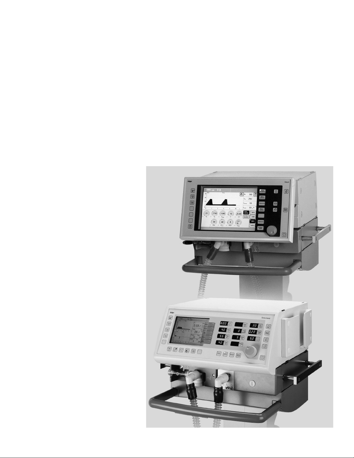
Evita 4 Sat
SpO2 Monitoring Option
Addendum to
Operating Instructions
Evita 4 / Evita 2 dura
D
MEDICAL
XXX
Page 2

NOTICE
Proprietary Information
This document contains information in which Draeger Medical, Inc.
claimed proprietary rights. The information may not be reproduced in
whole or in part except as authorized in writing by Draeger. This information is the property of Draeger Medical, Inc., it is provided solely for
the use intended.
Repairs/Modifications
Repairs on this device shall be performed only by DraegerService or its
Authorized Service Centers. Information about repairs can be obtained
from Draeger or Authorized Dealers. Draeger Medical, Inc. will not be
responsible for injury to persons or damage to property arising directly
or indirectly out of unauthorized repairs or modifications to this device.
Furthermore, any unauthorized repairs or modifications void any warranty extended by Draeger.
This document is provided for your information only. It will not be
exchanged or updated without request.
Trademarks
The Draeger name and logo are registered trademarks of Dräger.
OXISENSOR, DURASENSOR, AND OXIBAND are trademarks of
Nellcor Puritan Bennett Corporation
Dräger Medical AG & Co. KGaA, 2001
All rights reserved, Subject to modifications
Page 3

Contents
Contents
Important Safety Information READ THIS FIRST........4
Operator's Responsibility for Patient Safety..................4
Limitation of Liability..................................................... 4
Warranty......................................................................5
Definitions.................................................................... 6
General WARNINGS and CAUTIONS......................... 6
Precautions During Preparation.................................... 7
Precautions During Operation...................................... 7
Precautions During Maintenance.................................. 7
Intended Use.............................................................. 8
Preparation................................................................. 9
Installation....................................................................9
Sensor selection.......................................................... 9
C-Lock ECG synchronization..................................... 10
Operation With Evita 4.............................................. 11
Measuring SpO2 ....................................................... 11
Displaying the Plethysmogram ................................... 11
Setting Alarm Limits ...................................................12
Switching Off SpO2 Monitoring.................................. 13
Configuring Start Up Defaults for Alarm Limits ...........13
Operation With Evita 2 dura......................................14
Measuring SpO2 ....................................................... 14
Displaying the Plethysmogram ................................... 14
Setting Alarm Limits ...................................................15
Switching Off SpO2 Monitoring.................................. 15
Configuring Start Up Defaults for Alarm Limits ...........15
Ordering Information................................................ 26
Index......................................................................... 28
Applying SpO2-Sensors ........................................... 17
Tips to Avoid Artifacts ................................................17
Applying the Durasensor DS-100 A ........................... 18
Applying the Oxisensor D-25 and D-20 ......................19
Applying the Oxisensor I-20 .......................................19
Applying the Oxisensor R-15 ..................................... 20
Troubleshooting .......................................................21
Maintenance..............................................................22
Maintenance Intervals.................................................22
Technical Data.......................................................... 23
Theory of Operation..................................................24
SpO2 Measurement – Measuring Principle.................24
Operating Instructions Evita 4/Evita 2 dura Sat
3
Page 4

Important Safety Information
Operator's Responsibility for Patient Safety
Limitation of Liability
Important Safety Information
Operator's Responsibility for Patient Safety
For correct and effective use of the product and in
order to avoid hazards it is mandatory to carefully
read and to observe all portions of this manual.
The design of the intensive care ventilators this device
is intended to be used with, accompanying literature,
and the labeling on the equipment take into consideration that the purchase and use of the equipment are
restricted to trained professionals, and that certain
inherent characteristics of the equipment are known to
the trained operator. Instructions, warnings, and
caution statements are limited, therefore, largely to the
specifics of the Draeger design. This publication
excludes references to various hazards which are
obvious to a medical professional and operator of
respiratory care equipment, to the consequences of
misuse of such equipment, and to potentially adverse
effects in patients with abnormal conditions. Product
modification or misuse can be dangerous. Draeger
Medical, Inc. disclaims all liability for the consequences
of product alterations or modifications, as well as for
the consequences which might result from uses of the
product not covered by its intended use or from the
combination of this product with other products
whether supplied by Draeger or by other manufacturers
if such a combination is not endorsed by Draeger Medical, Inc..
Limitation of Liability
Draeger Medical, Inc.'s liability, whether arising out of
or related to manufacture and sale of the goods, their
installation, demonstration, sales representation, use,
performance, or otherwise, including any liability based
upon Draeger Medical, Inc.'s Product Warranty, is subject to and limited to the exclusive terms and conditions
as set forth, whether based upon breach of warranty or
any other cause of action whatsoever, regardless of
any fault attributable to Draeger Medical, Inc. and regardless of the form of action (including, without
limitation, breach of warranty, negligence, strict liability,
or otherwise).
THE STATED EXPRESSED WARRANTlES ARE IN
LlEU OF ALL OTHER WARRANTIES, EXPRESSED
OR IMPLIED, INCLUDING, WITHOUT LIMITATION,
WARRANTlES OF MERCHANTABILITY, FITNESS
FOR ANY PARTICULAR PURPOSE, OR
NONINFRINGEMENT.
Draeger Medical, Inc. shall not be liable for, nor shall
buyer be entitled to recover any special incidental, or
consequential damages or for any liability incurred by
buyer to any third party in any way arising out of or relating to the goods.
The operators of ventilator systems must recognize
their responsibility for choosing appropriate safety
monitoring that supplies adequate information on equipment performance and patient condition. Patient safety
may be achieved through a wide variety of different
means ranging from electronic surveillance of equipment performance and patient condition to simple,
direct observation of clinical signs. The responsibility
for the selection of the best level of patient monitoring
lies solely with the equipment operator.
4
Operating Instructions Evita 4/Evita 2 dura Sat
Page 5

Warranty
Important Safety Information
Warranty
All Draeger products are guaranteed to be free of defects for a period of one year from date of delivery.
The following are exceptions to this warranty:
1. The defect shall be a result of workmanship or
material. Defects caused by misuse, mishandling,
tampering, or by modifications not authorized by
Draeger Medical, Inc. or its representatives are not
covered.
2. Rubber and plastic components and materials arewarranted to be free of defects at time of delivery.
3. Oxygen sensors capsules have a six-month limited
warranty from the date of delivery.
Any product which proves to be defective in workmanship or material will be replaced, credited, or repaired
with Draeger Medical, Inc. holding the option. Draeger
Medical, Inc. is not responsible for deterioration, wear, or
abuse. In any case, Draeger Medical, Inc. will not be liable beyond the original selling price.
Application of this warranty is subject to the following
conditions:
1. Draeger Medical, Inc. or its authorized representative must be promptly notified, in writing, upon
detection of the defective material or equipment.
2. Defective material or equipment must be returned,
shipping prepaid, to Draeger or its authorized representative.
3. Examination by Draeger Medical, Inc. or its authorized representative must confirm that the defect is
covered by the terms of this warranty.
4. Notification in writing, of defective material or
equipment must be received by Draeger Medical,
Inc. or its authorized representative no later than
two (2) weeks following expiration of this warranty.
In order to assure complete protection under this
warranty, the Customer Registration Card and/or Periodic Manufacturer's Service Record (if applicable)
must be returned to Draeger within ten (10) days of
receipt of the equipment.
The above is the sole warranty provided by Draeger
Medical, Inc. No other warranty expressed or implied is
intended. Representatives of Draeger are not authorized to modify the terms of this warranty.
Operating Instructions Evita 4/Evita 2 dura Sat
Draeger Medical, Inc., Telford, PA
5
Page 6

Important Safety Information
Definitions
General WARNINGS and CAUTIONS
Definitions
WARNING !
A WARNING statement refers to conditions
with a possibility of personal injury if disregarded.
CAUTION !
A CAUTION statement designates the possibility
of damage to equipment if disregarded.
NOTE: A NOTE provides additional information
intended to avoid inconveniences during operation.
Inspection = examination of actual condition
Service = measures to maintain specified
condition
Repair = measures to restore specified
condition
Maintenance = inspection, service, and repair,
where necessary
General WARNINGS and CAUTIONS
WARNING !
Strictly follow Operator's Instruction Manuals
Any use of the product requires full under-
standing and strict observation of all portions
of these instructions as well as the Operating
Instructions of the Evita 4 and Evita 2 dura
ventilators, respectively. The equipment is only
to be used for the purpose specified under
"Intended Use" (page 8). Observe all WARNINGS and CAUTIONS as rendered throughout
the manuals and on labels on the equipment.
WARNING !
DANGER, risk of explosion if used in the
presence of flammable anesthetics.
The equipment is neither approved nor certified for use in areas where combustible or
explosive gas mixtures with air or with nitrous
oxide are likely.
WARNING !
Electrical connections to equipment which is
not listed in these Operating Instructions
should only be made following consultations
with the respective manufacturers or a
qualified expert.
Preventive = Maintenance measures at regular
Maintenance intervals
Typing conventions in this manual
Controls ("hard" keys and screen keys / fields / knobs)
are designated as »Control Name«, e.g.
»Configuration«
Screen pages are indicated as »Screen page«, e.g.
»Alarm limits«
On-screen messages are printed in bold, e.g.
SpO2 measurement is activated.
CAUTION !
Restriction of Distribution
Federal Law and Regulations in the United
States and Canada restrict this device to sale
by or on the order of a physician.
CAUTION !
Traceability
Federal Law in the United States requires traceability of this equipment. Please return the self
addressed registration card included with the
product and fill in the required information.
CAUTION !
Accessories
Use only accessories listed in the Ordering
Information (page 26).
Operating Instructions Evita 4/Evita 2 dura Sat
6
Page 7

Important Safety Information
Precautions During Preparation
Precautions During Operation
Precautions During Maintenance
Precautions During Preparation
WARNING !
Installation of the Evita 4 Sat Option may be
performed by factory trained and authorized
service personnel only.
WARNING !
Only use Nellcor OXISENSORS.
Observe all Instructions for Use of the
sensors. Incorrect positioning or use can
cause tissue damage.
Precautions During Operation
WARNING !
Never use sensors with damaged, exposed
electric wires.
Risk of electric shock.
Precautions During Maintenance
WARNING !
To avoid any risk of infection, clean and disinfect ventilator and accessories before any
maintenance according to established hospital procedures - this applies also when
returning ventilators or parts for repair.
WARNING !
Preventive Maintenance work on the Evita 4
and Evita 2 dura ventilators and their components may be performed by trained and
factory authorized staff only.
WARNING !
Never operate a ventilator if it has suffered
physical damage or does not seem to operate
properly. In this case always refer servicing to
properly trained and factory authorized service
personnel.
WARNING !
Keep cleaning fluid away from patient's eyes.
It will cause eye irritation. In case of contact
wash out with water immediately.
CAUTION !
Maintenance
In case of malfunction of this component, contact
your local DraegerService or our Factory
Authorized Technical Service Center.
The devices must be inspected and serviced
(preventive maintenance) by competent and
factory authorized technical service representatives at regular 6 month intervals. A record must
be kept on this preventive maintenance. We
recommend obtaining a service contract through
your vendor.
Maintenance or repair of Evita ventilators shall be
performed only by Draeger authorized technical
service representatives.
Operating Instructions Evita 4/Evita 2 dura Sat
7
Page 8

Intended Use
Intended Use
Evita 4 Sat – optional SpO2 monitoring for intensive care
ventilators Evita 4 or Evita 2 dura.
– For non-invasive measurement of functional oxygen
saturation in a patient's arterial blood.
– For measuring patient pulse rate.
– For monitoring functional oxygen saturation with upper
and lower alarm limits.
– For monitoring pulse rate with upper and lower alarm
limits.
Operating Instructions Evita 4/Evita 2 dura Sat
8
Page 9

Preparation
Installation
WARNING !
Installation of the Evita 4 Sat option
may be performed by factory trained and
authorized service personnel only.
Sensor Selection
Preparation
Installation
Sensor Selection
WARNING !
Only use Nellcor OXISENSORS.
Observe all Instructions for Use of the
sensors. Incorrect positioning or use can
cause tissue damage.
The table below is an aid to sensor selection, describing
the specific sensors available together with their
characteristics.
Sensor type OXISENSOR DURASENSOR OXISENSOR OXISENSOR OXISENSOR
D-20 DS-100 A I-20 R-15 R-15
Age group Children Adults Infants Adults Adults
Patient 10 to 50 kg >40 kg 3 to 20 kg >50 kg >30 kg
weight
Period of Short and long- Short-term Short and long- Short and long- Short and long-
use term monitoring monitoring term monitoring term monitoring term monitoring
Patient Limited activity Inactive Limited activity Inactive Inactive
mobility patients only patients only patients only
Preferred Finger Finger Toe Nose Finger
measuring
point
Sterility
1)
Sterile-packaging ––––––– Sterile-packaging Sterile-packaging –––––––
Operating Instructions Evita 4/Evita 2 dura Sat
1) in undamaged, unopened packaging
9
Page 10

Preparation
C-Lock ECG Synchronization
● Select the appropriate sensor.
1 Raise socket cover flap on the back of the ventilator.
2 Insert sensor plug.
NOTE: Use sensor extension cable (part no. 82 01 015)
if necessary
1
2
C-lock ECG Synchronization
In the event of considerable patient movement, or if the
patient's arterial circulation is very low, SpO2
measurement signals can be improved with C-Lock ECG
synchronization. In this case, the ventilator receives two
separate signals regarding heart activity:
– an optical signal from the SpO2 sensor
and
– an electrical signal from the ECG monitor.
Evita 4 and Evita 2 dura use the R-wave of the ECG
signal to detect patient pulse and to synchronize with the
SpO2 measurement.
● Connect ECG signal from the ECG monitor to the
back of the ventilator with cable and jack.
See "Technical Data" on page 23 for requirements
regarding input signal specifications and connector
pin Layout.
In the event of a delayed ECG signal
If the SpO2 signal is more than 40 milliseconds delayed
with respect to the QRS complex of the ECG signal,
synchronization may be adversaly affected.
If there is any suspicion of a problem of this type, use the
Evita 4 / Evita 2 dura without C-Lock ECG synchronization.
00128834
Operating Instructions Evita 4/Evita 2 dura Sat
ECG
Monitor
00228835
10
Page 11
Operation With Evita 4
Measuring SpO2
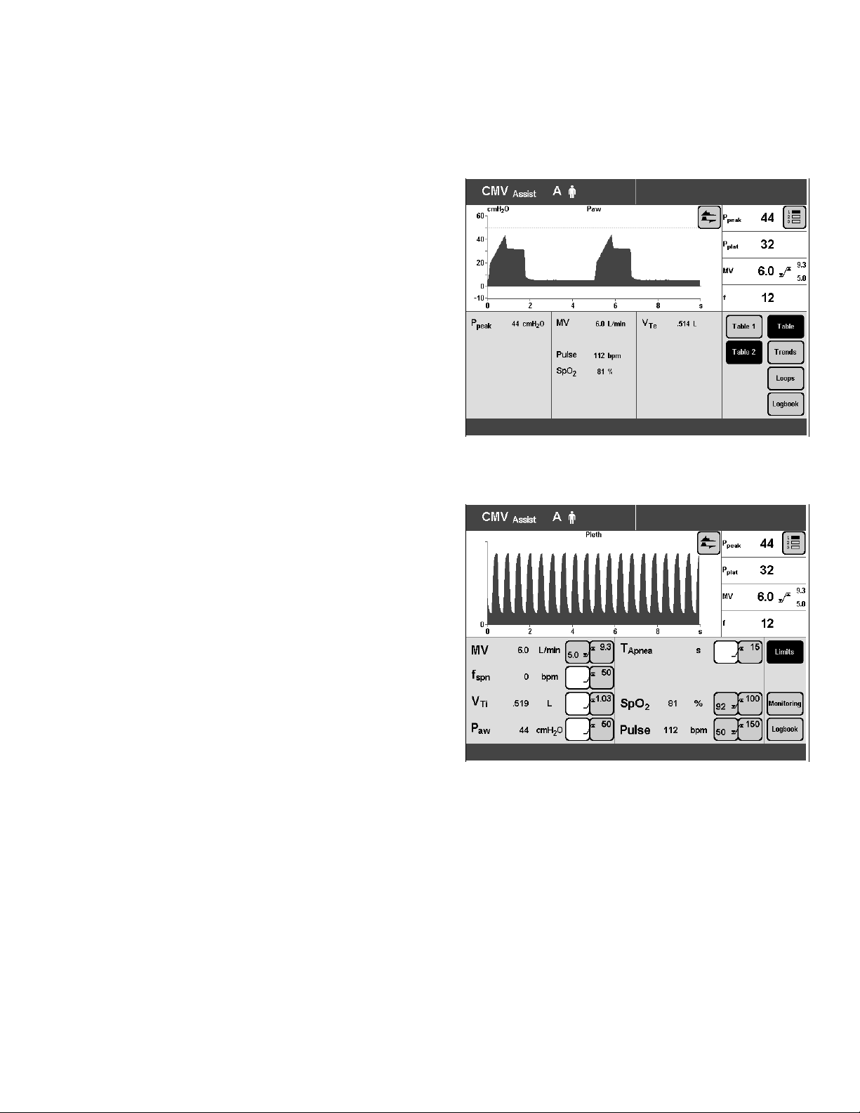
● Press »Measured Values« key.
● Touch »Table 2« screen key.
The measured values for SpO2 and pulse rate are
displayed in Table 2 of the »Measured Values« screen
page.
Operation With Evita 4
SpO2 Measurement
Plethysmogram Display
00428841
Displaying the Plethysmogram
Available in all screen pages.
If the »Pleth« waveform is not yet displayed on the
screen.
● Touch »π« screen key and
● touch »Pleth« screen key.
Example:
NOTE: If you wish to display the plethysmogram
permanently in the standard screen page, please refer to
Evita 4 Operating Instructions: Configuration ->Screen
-> SelectingWaveforms
00528841
Operating Instructions Evita 4/Evita 2 dura Sat
11
Page 12

Operation With Evita 4
Setting Alarm Limits
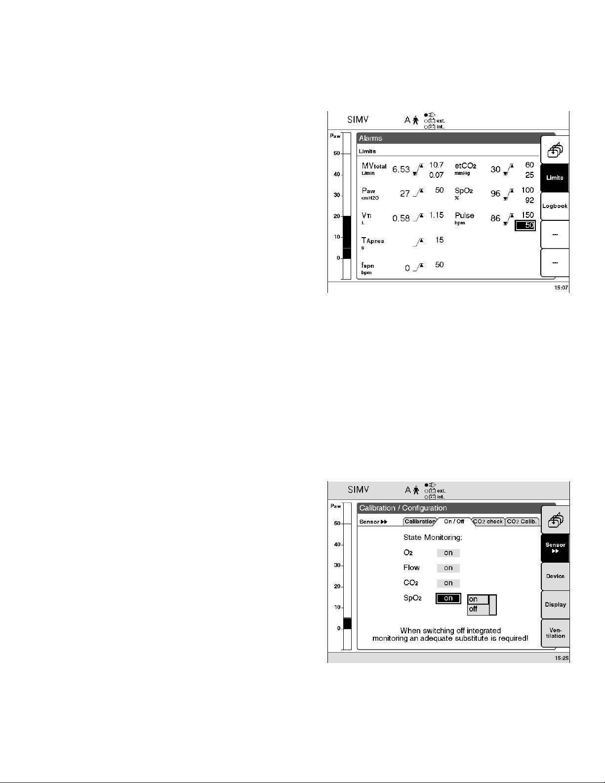
Setting Alarm Limits
● Press »Alarm limits« key.
● Note software version of unit.
Units with software version 3.n or lower:
The »Alarm limits« screen page is displayed
(example) for units with software version 3.n or lower:
All adjustable alarm limits are displayed on this page.
< = lower alarm limit
> = upper alarm limit
0062884100728841
Units with software version 4.n or higher:
● Touch »additional alarms« screen key.
The »additional alarms« screen page is displayed
(example) for units with software version 4.n or
higher:
The alarm limits for SpO2 and pulse rate are displayed
on this page.
Example:
To set lower alarm limit for pulse rate:
● Touch »< « screen key for the pulse rate lower alarm
limit: it will change color from green to yellow.
● Set alarm limit with the dial knob and press to confirm.
The new alarm limit will now be in effect.
Operating Instructions Evita 4/Evita 2 dura Sat
12
Page 13

Switching off SpO2 Monitoring
● Press »Alarm limits« key.
● Touch »Monitoring« screen key.
● Touch »SpO2« screen key.
● Press the dial knob to switch off SpO2 monitoring.
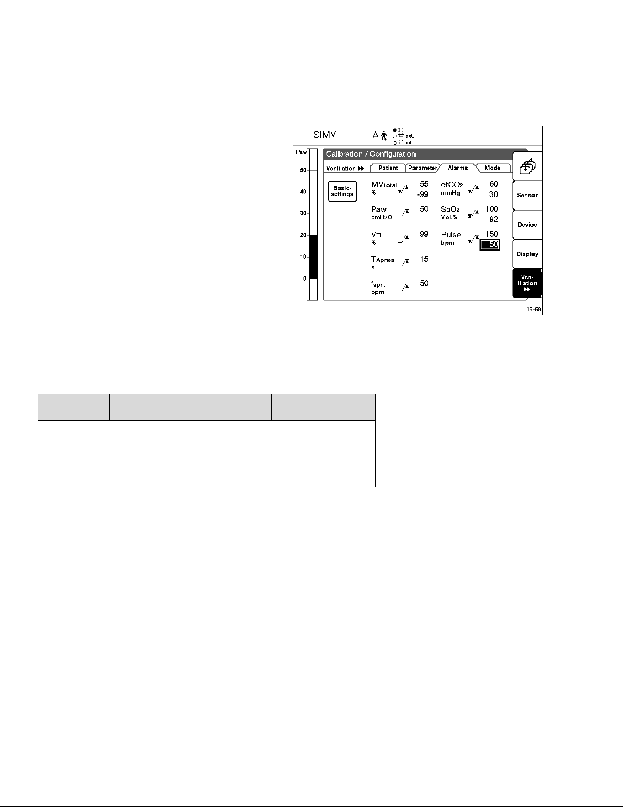
Configuring Start Up Defaults for
Alarm Limits
● Press »Configuration« key.
● Touch »Ventilation« screen key.
Enter access code 3032:
● Touch the respective screen keys.
Operation With Evita 4
Switching off SpO2 Monitoring
Configuring Start Up Defaults for Alarm Limits
● Touch »Start up settings« screen key.
● Touch »Alarm limits« screen key.
Display (example):
Defaults of the SpO2 and pulse alarm limits:
Measurement
parameter
SpO2 51 to 100 %
_
Pulse 21 to 250 bpm
_
Adjustment
range
50 to 99 %
20 to 249 bpm
Factory-set startup defaults
100 %
92 %
150 bpm
50 bpm
00828841
Hospital-specific
defaults
........................
........................
........................
........................
Any hospital-specific defaults selected for start-up may
be entered in the right-hand column of this table.
To modify these default alarm limits:
● Touch screen key of the alarm limit to be changed.
Operating Instructions Evita 4/Evita 2 dura Sat
● Change value = turn dial knob.
● Confirm value = press dial knob.
13
Page 14

Operation With Evita 2 dura
SpO2 Measurement
Plethysmogram display
Operation With Evita 2 dura
Measuring SpO2
● Press »Measured Values« menu key.
● Press »Table jj« menu key.
The measured values for SpO2 and pulse rate are
displayed in Table 2 of the »Measured Values« screen
page.
Displaying the Plethysmogram
● Press »Calib./Config.« menu key.
● Press »Display« menu key.
● By turning and pressing dial knob, select
screen position (top or bottom) and
in which set of waveforms (Set 1 or Set 2)
the plethysmogram is going to be displayed.
Example: Set 2 and display in top position
● Select top screen field in Set 2 = turn dial knob.
Confirm = press dial knob.
A list of available selections is displayed on the right
side of the screen,
● Select »Pleth« = turn dial knob.
● Confirm selection = press dial knob.
01028841
01128841
Operating Instructions Evita 4/Evita 2 dura Sat
14
Page 15
Setting Alarm Limits
● Press »Alarms« menu key.
● Press »Limits« menu key.
The »Alarm limits« screen page is displayed
(example):
All adjustable alarm limits are displayed on this page.
< = lower alarm limit
> = upper alarm limit
Example:
Operation With Evita 2 dura
Setting Alarm Limits
Switching off SpO2 Monitoring
To set lower alarm limit for pulse rate
● Select screen field with lower alarm limit
= turn dial knob.
Confirm = press dial knob.
● Set alarm limit by turning dial knob, press knob to
confirm. The new alarm limit will now be in effect.
Switching off SpO2 Monitoring
● Press »Calib./Config.« key.
● Select the »Sensors on/off« menu with
»Sensors jj« menu key.
● Select »SpO2« screen key = turn dial knob,
● Confirm = press dial knob.
● Switch off SpO2 monitoring = Select »off« by turning
dial knob, press knob to confirm.
01228841
Operating Instructions Evita 4/Evita 2 dura Sat
01328841
15
Page 16
Operation With Evita 2 dura
Configuring Start Up Defaults for Alarm Limits
Configuring Start Up Defaults for
Alarm Limits
● Press »Calib./Config.« menu key.
● Press »Ventilation« menu key.
Enter access code 3032:
● Turn and press dial knob in order to enter respective
digits one at a time.
● Select »Alarms« menu screen by pressing
»Ventilation jj« twice. »Alarms« screen page will
appear.
Display (example):
01428841
Defaults of the SpO2 and pulse alarm limits:
Measurement
parameter
SpO2 51 to 100 %
_
Pulse 21 to 250 bpm
_
Adjustment
range
50 to 99 %
20 to 249 bpm
Factory-set startup defaults
100 %
92 %
150 bpm
50 bpm
Any hospital-specific defaults selected for start-up may
be entered in the right-hand column of this table.
To modify start-up defaults of alarm limits (e.g. lower
alarm limit for pulse rate):
● Select "Pulse" lower alarm limit = turn dial knob.
Confirm selection = press dial knob.
● Change value = turn dial knob.
● Confirm value = press dial knob.
Hospital-specific
setting
........................
........................
........................
........................
Operating Instructions Evita 4/Evita 2 dura Sat
16
Page 17

Applying SpO2 Sensors
Tips to Avoid Artifacts
Nellcor compatible sensors must be used exclusively,
and they must be correctly positioned to avoid the risk of
measuring artifacts and of tissue damage.
WARNING !
Never use sensors with damaged, exposed
electric wires.
Risk of electric shock.
Oxiband-OXI-A/N and OXI-P/I adhesive strips must not
be reused, because they might not adhere properly.
Do not overstretch adhesive strips.
Never double-up strips, as this may lead to venous
pulsation and failure of the pulse signal.
Applying SpO2-Sensors
Tips to Avoid Artifacts
High intrathoracic pressure, pressure on the thorax and
other consequential impairments of venous flow can lead
to venous pulsation with failure of the pulse signal.
The pulse signal may fail in the presence of shock, low
blood pressure, severe vasoconstriction, major anemia,
hypothermia, arterial occlusion proximal to the sensor,
and asystole.
In the presence of bright light (e.g. from surgical lamps
or direct sunlight), the sensor must be covered,
otherwise the pulse signal may fail or become inaccurate.
The sensor should not be positioned on extremities
together with an arterial catheter, sphygmomanometer
cuff or intravascular venous infusion: the pulse signal
may fail, and measurement may become inaccurate.
Measurement accuracy may also be impaired in the
event of significant concentrations of dysfunctional hemoglobins, such as carboxyhemoglobin or methemoglobin.
Intravascular dyes, such as methylene blue, may also impair measurement accuracy.
Electrosurgery can impair measuring accuracy; leads and
sensor should therefore be positioned as far away as
possible from the site of electrosurgery and its neutral
electrode.
Sensor performance may be impaired if the patient
moves excessively, leading to inaccurate results. In such
cases the sensor should be applied to a different location
in order to reduce the likelihood of movement artifacts.
Operating Instructions Evita 4/Evita 2 dura Sat
17
Page 18
Applying SpO2-Sensors
Applying the Durasensor DS-100 A
Applying the Oxisensor D-25 and D-20
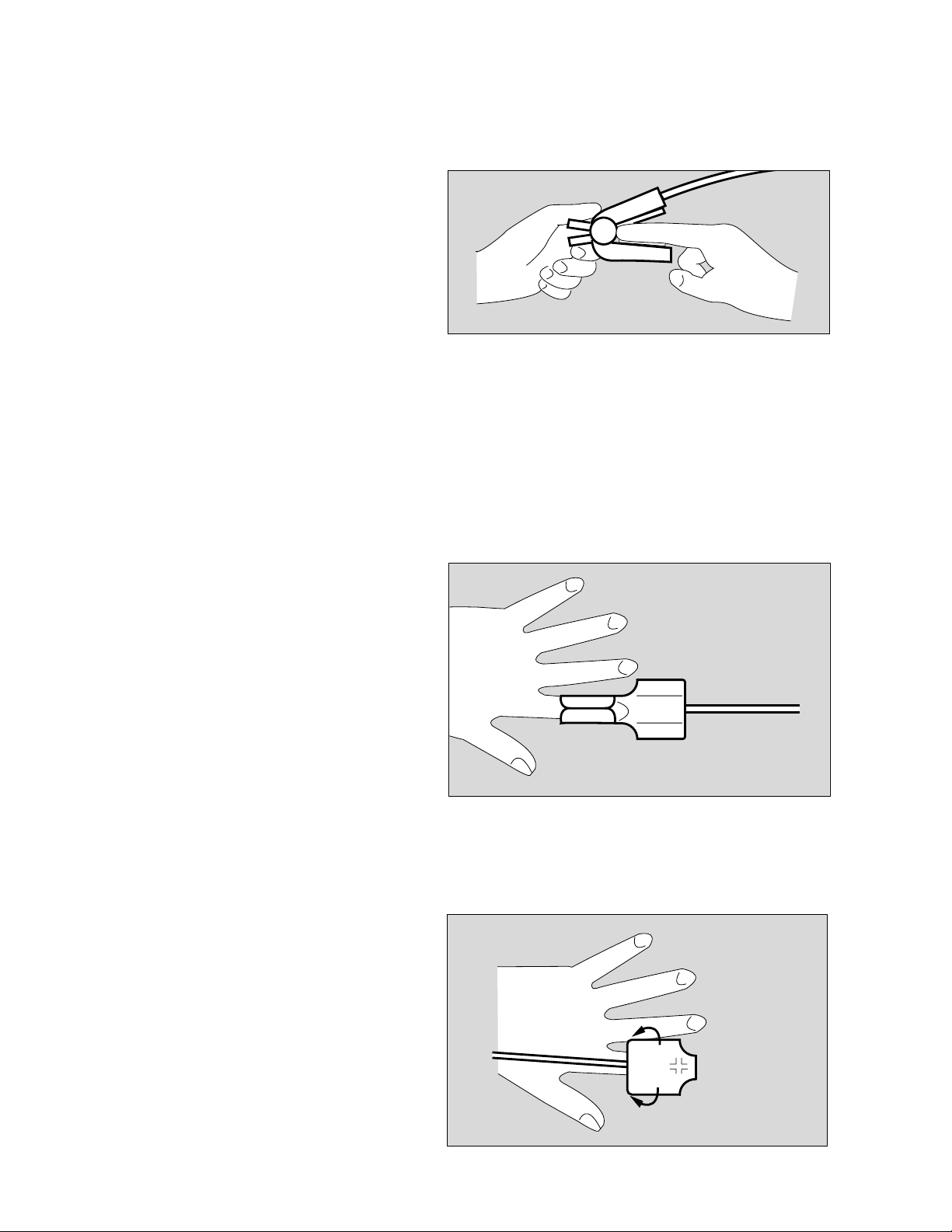
Applying the Durasensor DS-100 A
Reusable sensor for short term monitoring of relatively
quiet patients weighing over 40 kg.
The sensor is preferably positioned on the index finger,
although other fingers may also be used. The little finger
should be used if the patient is particularly large or
obese.
● Open clip slightly and slide sensor onto the finger.
The tip of the finger must touch the end, and the soft
padding must rest on the nail and tip of the finger.
The lead should be on top of the finger.
● Verify that the finger is not compressed or hurt by the
clip.
● Change the application site at least every 4 hours in
order to avoid impairing blood circulation.
01528834
Applying the Oxisensor D-25 and D-20
Adhesive sensors for short and long-term monitoring of
patients with limited mobility weighing from 15 to more
than 50 kg.
Long fingernails make application of the sensor more
difficult, and colored nail varnish impairs accuracy of
measurement.
● Cut fingernail if necessary.
● Remove nail varnish if necessary.
Then:
● Remove protective film from adhesive strip.
● Place sensor on a flat surface with adhesive side
facing upwards.
● Center tip of patient's index finger onto optical
element located opposite the cable end. Wrap
adhesive strips around finger.
● Fold the cable end of the sensor over the tip of the
finger, and position so that the markings on both
sides line up correctly. Press sensor gently into place
and wrap remaining adhesive strips around the finger.
01628834
Operating Instructions Evita 4/Evita 2 dura Sat
A thinner finger should be used instead of the index
finger if the patient is very obese.
18
01728834
Page 19

Applying the Oxisensor I-20
Adhesive sensor for short and long-term monitoring of
patients with limited mobility and weighing between
3 and 15 kg.
● Remove protective film from adhesive strip.
● Place sensor underneath the big toe, so that the
dotted line is on the inner edge of the toe and the
marking is positioned on the middle of the toe.
● Wrap sensor strip around the toe so that the other
marking is exactly on top of the toenail.
● Secure sensor cable to the foot with the additional
adhesive tape provided.
Applying SpO2-Sensors
Applying the Oxisensor I-20
01828834
Reusing the sensor
The sensor can be reused if the tape is still sticky.
Adhesion is improved by small additional adhesive spots.
● Hold adhesive spots by their blue tabs, peel them off
the backing paper and remove protective film.
● Affix one spot concentrically to each optical element.
● Position sensor as described above.
Other measuring point
The sensor is preferably applied to the big toe because
the toe moves less than a patient's hand. If the big toe
cannot be used, however, the sensor may also be
applied to the thumb.
● Peel protective film off adhesive strip.
● Position the sensor under the thumb so that the
dotted line is on the inner edge of the thumb and the
marking is positioned on the middle of the thumb.
0192883402028834
● Wrap the sensor round the thumb so that the other
marking is exactly on top of the thumbnail.
Operating Instructions Evita 4/Evita 2 dura Sat
● Secure sensor cable to the hand with the additional
adhesive tape provided.
02128834
19
Page 20

Applying SpO2-Sensors
Applying the Oxisensor R-15
Applying the Oxisensor R-15
Disposable adhesive sensor for short and long-term
monitoring of immobile patients weighing more than
50 kg. Preferably used for patients likely to be suffering
from severe vasoconstriction or poor circulation.
● Clean bridge of patient's nose with cleaning fluid in
enclosed ampule.
WARNING !
Keep cleaning fluid away from patient's eyes.
It will cause eye irritation. In case of contact
wash out with water immediately.
● Peel off the protective backing
● Align sensor symmetrically on the bridge of the nose:
the two symbols should be placed on the bone/
cartilage boundary.
● Press sensor gently into place and hold for
10 seconds to ensure good adhesion.
NOTE: The R-15 sensor may not be used on patients
with nasal intubation or a mask.
02228834
Operating Instructions Evita 4/Evita 2 dura Sat
20
Page 21

Troubleshooting
Troubleshooting
Alarm messages in the alarm display field are displayed
in hierarchical order.
If, for example, two faults are detected at the same time,
the more urgent of the two is displayed.
The priority for alarm messages is indicated by
exclamation marks:
Warning = Message with top priority !!!
Caution = Message with medium priority !!
Advisory = Message with low priority !
Message Cause Remedy
No Pulse !!!
Pulse high !!!
Pulse low !!!
SpO2 high !!!
SpO2 sensor detached Check SpO2 sensor attachment
Pulse rate exceeds upper alarm limit. Check patient condition.
Pulse rate below lower alarm limit. Check patient condition.
SpO2 exceeds upper alarm limit. Check patient condition.
In the table below, the messages are listed in alphabetical order.
The table should help you to identify the cause of an
alarm and to ensure rapid remedy of the problem.
Check ventilation pattern.
If necessary, adjust alarm limit.
Check ventilation pattern.
If necessary, adjust alarm limit.
Check ventilation pattern.
If necessary, adjust alarm limit.
SpO2 low !!!
SpO2 measurement inop !!!
SpO2 sensor !!!
Operating Instructions Evita 4/Evita 2 dura Sat
SpO2 below lower alarm limit. Check patient condition.
Check ventilation pattern.
If necessary, adjust alarm limit.
SpO2 sensor defective. Replace sensor.
SpO2 measurement defective. Call DraegerService.
The plug of the SpO2 sensor was
disconnected during operation.
Sensor defective. Use new sensor.
Reconnect the sensor plug.
Test.
21
Page 22

Troubleshooting
Maintenance
CAUTION !
Maintenance
In case of malfunction of this component, contact
your local DraegerService or our Factory
Authorized Technical Service Center.
The devices must be inspected and serviced
(preventive maintenance) by competent and
factory authorized technical service representatives at regular 6 month intervals. A record must
be kept on this preventive maintenance. We
recommend obtaining a service contract through
your vendor.
Maintenance or repair of Evita ventilators shall be
performed only by Draeger authorized technical
service representatives.
WARNING !
To avoid any risk of infection, clean and disinfect ventilator and accessories before any
maintenance according to established hospital procedures - this applies also when returning ventilators or parts for repair.
Maintenance Intervals
Preventive maintenance Every 6 months by trained
and factory authorized
service personnel.
The Evita 4 Sat option is serviced as part of the
scheduled preventive maintenance of the Evita 4 and
Evita 2 dura ventilators every six months.
WARNING !
Preventive Maintenance work on the Evita 4
and Evita 2 dura ventilators and their components may be performed by trained and
factory authorized staff only.
WARNING !
Never operate a ventilator if it has suffered
physical damage or does not seem to operate
properly. In this case always refer servicing to
properly trained and factory authorized service
personnel.
Operating Instructions Evita 4/Evita 2 dura Sat
22
Page 23

Technical Data
Ambient conditions
During operation
Temperature 10 to 40 °C (50 to 104 °F)
Atmospheric pressure 700 to 1060 hPa
Rel. humidity 0 to 90 %
During storage and transport
Temperature –20 to 60 °C (-4 to 140 °F)
Atmospheric pressure 500 to 1060 hPa
Rel. humidity 0 to 100 %
SpO2 measurement
Display range 0 to 100 % SpO2
Accuracy (adults)
range 70 to 100 % SpO2 better than ±2 % SpO2
range 50 to 70 % SpO2 better than ±3 % SpO2
range 0 to 50 % SpO2 not specified
Technical Data
Accuracy (neonates)
in the 70 to 95 % SpO2 range better than ±3 % SpO2
in the 0 to 70 % SpO2 range not specified
in the 95 to 100 % SpO2 range not specified
Pulse rate 20 to 250/min
Accuracy ±2/min
Sensors
Type Nellcor compatible sensors
Oxisensor, Oxiband and Durasensor
Wavelengths 660 nm (red),
920 nm (infrared)
C-Lock ECG Synchronization
Prerequisite for ECG
synchronization signal pos. pulse with voltage >4.5 V,
>10 ms for driving 2 mA.
Max. permissible delay of the
signal with reference to the current
QRS complex 40 ms
Ground
Socket for 2-pole 3.5 mm barrel connector
Jack contact assignment
Signal
Signal isolation from other
electronic components
Operating Instructions Evita 4/Evita 2 dura Sat
Dielectric strength 4 kV
23
Page 24

Theory of Operation
SpO2 Measurement – Measuring Principle
Theory of Operation
SpO2 Measurement – Measuring Principle
Oxygenated, arterial blood (oxyhemoglobin, HbO2) has
light absorption properties different from unsaturated,
venous blood (reduced hemoglobin, Hb). "O2 saturation"
is a logarithmic function of light intensity absorbed by the
blood (Lambert-Beer's law).
The effect of dysfunctional hemoglobins, such as carbon
monoxide hemoglobin (HbCO) and methemoglobin
(MetHb), is negligible under normal circumstances.
The sensor consists of two light-emitting diodes which
alternately emit infrared light with typical wavelengths of
920 nm and 660 nm, respectively.
A photodetector placed opposite the LEDs measures the
intensity of radiation. The sensor is attached to a part of
the body where arterial blood vessels can be transluminated, e.g. finger, toe, bridge of the nose.
Light-emitting diodes
Photodetector
Infrared light (920 nm)
Red light (660 nm)
02328835
These two wavelengths (920 nm and 660 nm) have been
chosen because, even in the presence of slight
perfusion, they still provide meaningful absorption values
for both oxygenated and reduced blood, while at the
same time they differ significantly.
Total absorption of light emitted alternately by the diodes
is caused by the pulsating arterial blood, the skin, finger
nails, muscular tissue, bones, venous blood.
Except for the pulsating, arterial blood, absorption by all
the other components during a defined period of time
remains constant as far as volume and optical density are
concerned.
By contrast, the arterial blood pulsating with every heart
beat causes a pulse-synchronized volume change in the
transluminated tissue, and consequently a pulse-synchronized change of absorption of the light transmitted.
Light absorption is first measured while no pulsating
blood is present in the tissue(during diastole). This
measurement renders a value for light absorbed by the
tissue and by non-pulsating blood.
20 000
10 000
5 000
1 000
500
Absorption coefficient
100
50
10
500 650 750 850 950
Reduced haemoglobin Hb
Oxygenated haemoglobin HbO2
Absorption
660 nm
Red
920 nm
Infrared
Wavelength nm
Absorption by
arterial blood
Absorption by
venous blood
Absorption by
other tissues
(incl. skin)
Time (s)
02428835
Operating Instructions Evita 4/Evita 2 dura Sat
02528835
24
Page 25

Normally, this does not change during a pulse phase so it
serves as a reference value for the pulsating part of
absorption.
The absorption is then measured after the next heart
beat, when pulsating blood enters the tissue. During this
measurement, light absorption for both wavelengths
changes due to the pulsating arterial blood.
Theory of Operation
SpO2 Measurement – Measuring Principle
The diagram shows an example of the light absorption
characteristics of the blood at 660 nm (red) and 920 nm
(infrared). With increasing O2 saturation, the absorption
and corresponding pulse amplitude fall at 660 nm but
rise at 920 nm. Since the absorption coefficients of
HbO2 and Hb are known for both wavelengths, the
system can calculate the quantity of each of these two
haemoglobins present in the blood.
The quotient obtained by dividing oxygenated haemoglobin (HbO2) by the combination of reduced and
oxygenated haemoglobin (Hb+HbO2) is termed the
"functional saturation":
% SpO2 = 100 x
HbO
2
HbO2 + Hb
This value refers to the hemoglobin which is available to
transport oxygen.
The dysfunctional hemoglobins, HbCO and MetHb, can
be ignored under normal circumstances, they might,
however, impair the accuracy of measurements.
O2 saturation O2 saturation 100 %
at 660 nm red
Pulse amplitude
Time (s)
at 920 nm infrared
Pulse amplitude
Time (s)
02628835
Operating Instructions Evita 4/Evita 2 dura Sat
25
Page 26

Ordering Information
Ordering Information
Item/Description Part No.
SpO2 kit (Evita 4 Sat) 84 13 035
consisting of:
SpO2 module 86 00 481
Durasensor DS-100 A 82 01 001
Sensor extension cable 82 01 015
Accessories
Finger sensor Dura DS-100 A 82 01 001
Adhesive sensor D 25 (pack of 24) 82 01 002
Adhesive sensor D 25 (pack of 6) 82 01 035
Adhesive sensor D 25 L (pack of 24) 21 70 175
Adhesive sensor D 20 (pack of 24) 82 01 003
Adhesive sensor D 20 (pack of 6) 82 01 036
Adhesive sensor I 20 (pack of 24) 82 01 004
Adhesive sensor I 20 (pack of 6) 82 01 037
Adhesive sensor R 15 (pack of 12) 82 01 006
Adhesive sensor R 15 (pack of 6) 82 01 039
OXIBAND adhesive sensor, compl. 82 01 013
OXIBAND adhesive strip (pack of 50) 82 01 012
Sensor extension cable 82 01 015
Operating Instructions Evita 4/Evita 2 dura Sat
26
Page 27

Index
Advisory.......................................................................6
Alarm......................................................................... 21
Alarm limits...........................................................12, 15
Artifacts......................................................................17
Caution........................................................................6
C-Lock ECG Synchronization.....................................10
Default, alarms at start-up.................................... 12, 15
Durasensor DS-100 A................................................ 19
Intended use................................................................8
Order list....................................................................26
Oxisensor D-20.......................................................... 19
Oxisensor D-25.......................................................... 19
Oxisensor I-20............................................................19
Oxisensor R-15.......................................................... 20
Index
Plethysmogram.................................................... 11, 14
Preparation.................................................................10
Safety, patient..............................................................4
Sensor, selecting......................................................... 9
SpO2 measurement, activating..................................... 9
SpO2, measuring..................................................11, 14
SpO2 sensor, applying............................................... 17
Technical Data........................................................... 23
Theory, of operation....................................................24
Troubleshooting..........................................................21
Use, intended.............................................................. 8
Warning.......................................................................6
Operating Instructions Evita 4/Evita 2 dura Sat
27
Page 28

These Operating Instructions apply only
¿ to Evita 4 with Serial No.:
¿ to Evita 2 dura with Serial No.:
(check applicable)
Without entry of a Serial No. by Draeger
these Operating Instructions are provided
for general information only and are not
intended for use with a specific device.
Draeger Medical, Inc.
H 3135 Quarry Road
Telford, PA 18969
T 215-721-5400
FAX 215-723-5935
90 28 841 - GA 5664.504 enUS
Dräger Medical AG & Co. KGaA
3rd edition - May 2001
Subject to modifications
 Loading...