

Page 1
Technical Service Manual
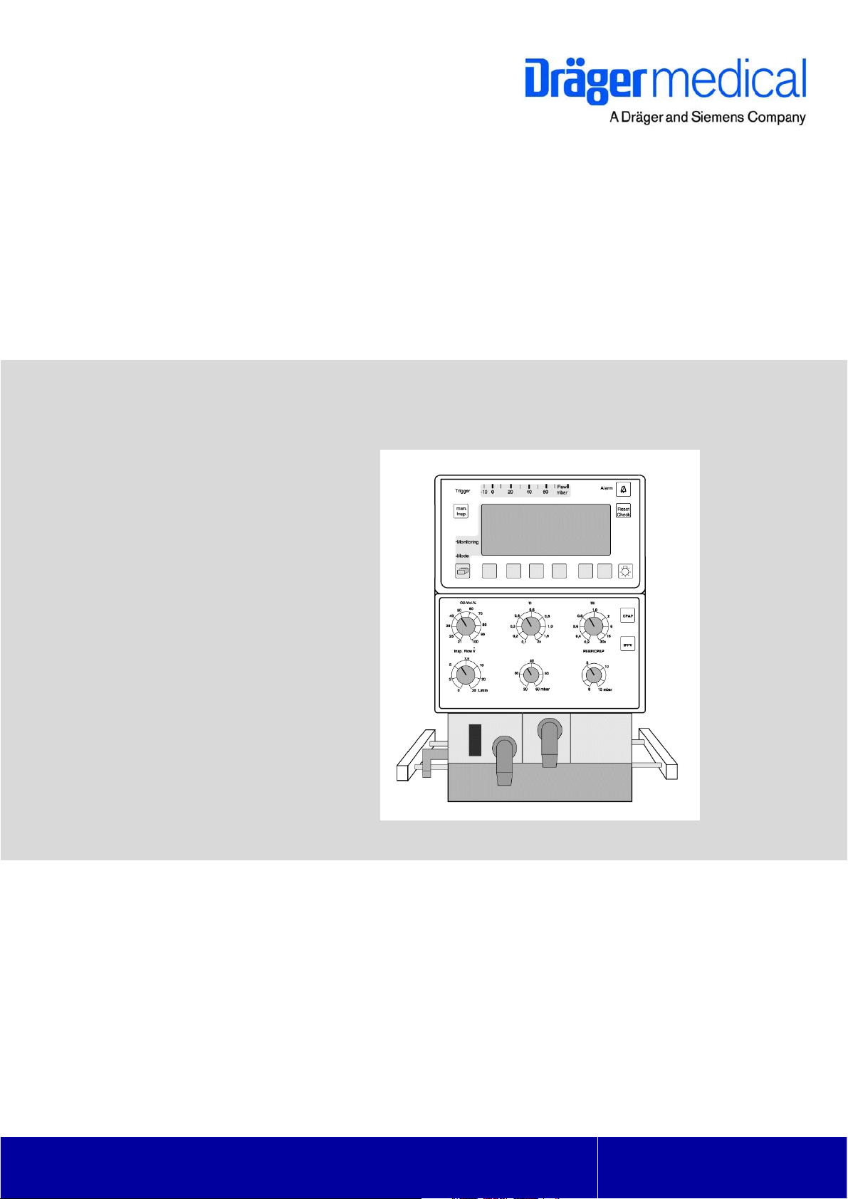
Babylog 8000/8000SC/8000 plus
Intensive Care Ventilator
Emergency Care • Perioperative Care • Critical Care • Perinatal Care • Home Care
Revision 10.0
6173.3
9029623
Because you care
Page 2

Copyright by Dräger Medical AG & Co. KGaA, Lübeck, Germany.
No reproduction allowed for commercial purposes.
Read and understand the Instructions for Use/Operator’s Manual.
This Technical Documentation does not replace the Instructions for Use/Operator’s
Manual.
The warranty and liability conditions of the general terms and conditions for business
transactions of Dräger Medical AG & Co. KGaA are not extended by this Technical
Documentation.
Observe all applicable technical laws and regulations.
Insofar as reference is made to laws, regulations or standards, these are based on the
legal system of the Federal Republic of Germany. Observe the laws and regulations
applicable in your country.
Page 3

Contents
General
1 Notes 9
1.1 Symbols and Definitions ......................................................................................................... 9
Function Description
1 General 13
1.1 Ventilation Modes ................................................................................................................. 13
1.2 Additional Functions ............................................................................................................. 13
1.3 Monitoring ............................................................................................................................. 13
2 Block Diagrams 14
2.1 Block Diagram of the Components in
Babylog 8000/Babylog 8000 SC with LC Display 14
2.2 Block Diagram of the Components in
Babylog 8000/Babylog 8000 plus with EL Display 15
2.3 Block Diagram of the Babylog 8000/ Babylog 8000 plus/Babylog 8000 SC ........................ 16
3 Airway Monitoring 17
3.1 Airway Pressure ................................................................................................................... 17
3.2 Trigger Signal ....................................................................................................................... 17
3.3 Measurement of the Fraction of Inspired O2 ....................................................................... 17
3.4 Patient Flow (Babylog 8000/Babylog 8000 plus) .................................................................. 18
4 Monitoring Functions 19
4.1 Fraction of inspired O
(FiO2) ............................................................................................... 19
2
4.1.1 O
4.1.2 O
Measurement .................................................................................................... 19
2
Calibration ......................................................................................................... 19
2
4.2 Gas Supplies ........................................................................................................................ 20
4.3 Airway Pressure Monitoring ................................................................................................. 20
4.4 Disconnect Monitoring ..........................................................................................................20
4.5 Overpressure and Low Pressure Alarms ............................................................................. 21
All rights reserved. Copyright reserved.
GBK61733XXIECIVZ.fm 18.05.05
Dräger Medical AG & Co. KGaA Contents
I
Page 4

Contents
4.5.1 Babylog 8000 up to Software Version 3.0 ...............................................................21
4.5.2 Dynamic Stenosis Limit ...........................................................................................21
4.6 Minute Volume Monitoring (Babylog 8000/Babylog 8000 plus) ............................................ 23
4.6.1 Babylog 8000 with Software Versions 2 and 3 ....................................................... 23
4.6.2 Babylog 8000 Software with Version 4.0 or Higher ................................................ 23
4.6.3 Babylog 8000 plus ..................................................................................................23
4.7 Audible Alarm Generator Monitoring ....................................................................................23
4.8 Operating Voltage Monitoring ...............................................................................................23
4.9 Rotary Potentiometer Monitoring .......................................................................................... 23
4.10 ROM Test ..............................................................................................................................24
4.11 RAM Test ..............................................................................................................................24
4.12 Temperature Monitoring ........................................................................................................24
4.13 Relay and Valve Monitoring ..................................................................................................24
4.14 Battery Monitoring ................................................................................................................24
4.15 Flow Measurement Monitoring (Babylog 8000/ Babylog 8000 plus) ....................................24
5 Alarms, Cautions and Advisory Messages 25
5.1 Message Display .................................................................................................................. 25
5.2 Display and Menu .................................................................................................................25
5.2.1 Babylog 8000/Babylog 8000 SC with LC Display ...................................................26
5.2.2 Babylog 8000/Babylog 8000 plus with EL Display .................................................. 26
6 Function of the Control Elements 27
6.1 Potentiometers (Rotary Knobs) ............................................................................................ 27
6.1.1 Fraction of inspired O
6.1.2 Inspiratory time (T
(O2 vol.%) .......................................................................... 27
2
) .................................................................................................27
I
All rights reserved. Copyright reserved.
6.1.3 Expiratory time (T
) ................................................................................................27
E
6.1.4 Inspiratory flow (Insp. Flow) .................................................................................... 27
6.1.5 Inspiratory pressure limit (P
) .............................................................................27
insp
6.1.6 PEEP/CPAP ............................................................................................................27
6.2 Keys ......................................................................................................................................28
II
Dräger Medical AG & Co. KGaA Contents
GBK61733XXIECIVZ.fm 18.05.05
Page 5

Contents
6.2.1 CPAP ...................................................................................................................... 28
6.2.2 IPPV/IMV (CMV) (up to software version 4.n) ........................................................ 28
6.2.3 Man. Insp. ............................................................................................................... 28
6.2.4 2-min Silence .......................................................................................................... 28
6.2.5 Reset/Check (OK) .................................................................................................. 28
6.2.6 Backlight On/Off (Babylog 8000/8000 SC with LC Display) ................................... 28
6.2.7 "Cal. Config." (as of software version 5.n) .............................................................. 29
6.2.8 Keys ....................................................................................................................... 29
7 Cold Start/Warm Start Behavior 30
7.1 Cold-Start Behavior .............................................................................................................. 30
7.2 Warm-Start Behavior ............................................................................................................30
8 Description of Pneumatic Functions 31
8.1 Gas Supplies ........................................................................................................................ 31
8.2 Controlled Ventilation ........................................................................................................... 32
8.2.1 Inspiration ............................................................................................................... 32
8.2.2 Expiration ............................................................................................................... 33
8.2.3 PEEP ...................................................................................................................... 33
8.2.4 CPAP ...................................................................................................................... 33
9 Measurement of the Ventilation Parameters 34
9.1 O2 Measurement .................................................................................................................. 34
9.2 Measurement of the Airway Pressure .................................................................................. 34
9.3 Pneumatics Control PCB ...................................................................................................... 35
9.4 Pneumatics Analog PCB ...................................................................................................... 36
9.5 Patient System Heater ......................................................................................................... 37
9.6 Pressure Sensor Base PCB ................................................................................................. 37
9.7 O2 Amplifier PCB ................................................................................................................. 37
10 Components of the Electronic Assembly 38
10.1 Power Supply Unit ................................................................................................................ 38
All rights reserved. Copyright reserved.
GBK61733XXIECIVZ.fm 18.05.05
Dräger Medical AG & Co. KGaA Contents
III
Page 6

Contents
10.2 Motherboard PCB ................................................................................................................. 38
10.3 CPU 68000 PCB ...................................................................................................................39
10.4 I/O PCB ................................................................................................................................40
10.5 Flow PCB (Babylog 8000/Babylog 8000 plus) (optional) ...................................................... 41
10.6 Monitoring PCB ....................................................................................................................42
10.6.1 Measurement of Analog Signals .............................................................................42
10.6.2 Measurement of Digital Inputs ................................................................................42
10.6.3 Measurement of Digital Outputs ............................................................................. 42
10.7 Front Adapter PCB ...............................................................................................................45
10.8 Front Controller PCB
(Babylog 8000/Babylog 8000 SC with LC Display) 46
10.9 Front PCB (Babylog 8000/Babylog 8000 plus with EL Display) ........................................... 47
10.10Display PCB (Babylog 8000/Babylog 8000 SC with LC Display) .........................................48
10.11EL display (Babylog 8000/Babylog 8000 plus with EL Display) ........................................... 49
10.12Potentiometer Field .............................................................................................................. 50
10.13Display Field .........................................................................................................................50
10.14Communication PCB ............................................................................................................ 51
10.15Interface PCB .......................................................................................................................52
11 Sensors 53
11.1 Pressure Sensors .................................................................................................................53
11.2 Y-Piece with Flow Sensor (Babylog 8000/Babylog 8000 plus) .............................................53
11.2.1 Measuring Principle of the Flow Measuring Bridge ................................................ 54
11.3 O2 Sensor ............................................................................................................................55
All rights reserved. Copyright reserved.
IV
GBK61733XXIECIVZ.fm 18.05.05
Dräger Medical AG & Co. KGaA Contents
Page 7

Contents
Replacing Non Repairable Items
1 Important Information 59
2 Cleaning or Replacing the Cooling Air Filter Every 4 Weeks 60
3 Replacing the O
3.1 O
Sensor Calibration ........................................................................................................... 61
2
3.2 Calibrating the O
3.3 Disposing of the O
Sensor Capsule 61
2
Sensor After Replacement ...................................................................... 61
2
Sensor Capsule .................................................................................... 63
2
4 Replacing the Lip Seals Every 2 Years 64
5 Replacing the NiCd Battery (Power Failure Alarm) Every 2 Years 65
6 Replacing the Pressure Reducer Every 6 Years 67
Schematics and diagrams
1 Schematics and Diagrams 77
Error List
1 Error messages 91
2 List of device error messages 92
Annex
Spare parts list 97
Test List 97
Technical Information according to EMC standard IEC/EN 60601-1-2:2001 97
All rights reserved. Copyright reserved.
GBK61733XXIECIVZ.fm 18.05.05
Dräger Medical AG & Co. KGaA Contents
V
Page 8

Contents
VI
All rights reserved. Copyright reserved.
GBK61733XXIECIVZ.fm 18.05.05
Dräger Medical AG & Co. KGaA Contents
Page 9

General
7
Page 10

8
Page 11
Babylog 8000 General
1Notes This Technical Documentation/Service Manual conforms to the International
Standard IEC 60601-1.
Read each step in every procedure thoroughly before beginning any test.
Always use the proper tools and specified test equipment. If you deviate from
the instructions and/or recommendations in this Technical Documentation/Service Manual, the equipment may operate improperly or unsafely, or
the equipment could be damaged.
Use only original Dräger parts and supplies.
The maintenance procedures described in this Technical Documentation/Service Manual may be performed by qualified service personnel only.
These maintenance procedures do not replace inspections and servicing by
Dräger Medical AG & Co. KGaA.
Strictly follow the Instructions for Use/Operating Instructions! This
Technical Documentation does not replace the Instructions for
Use/Operating Instructions. Any use of the product requires full
understanding and strict observation of the product-specific Instructions for Use/Operating Instructions.
1.1 Symbols and Defini-
tions
Unless otherwise stated, reference is made to laws, regulations or standards (as amended) applicable in the Federal Republic of Germany.
This symbol indicates a warning.
This symbol indicates tips and useful information.
This symbol is used to alert against unsafe practices when handling electrostatic sensitive devices (ESD).
Definitions according to German standard DIN 31051:
Inspection = examination of actual condition
Maintenance = measures to maintain specified condition
Repair = measures to restore specified condition
Servicing = inspection, maintenance, and repair
All rights reserved. Copyright reserved.
Version 1.0_ Released_Printed on_18.05.05_GBK61733XXA01.fm
Dräger Medical AG & Co. KGaA 6173.3
9
Page 12

General Babylog 8000
10
Dräger Medical AG & Co. KGaA 6173.3
Version 1.0_ Released_Printed on_18.05.05_GBK61733XXA01.fm
All rights reserved. Copyright reserved.
Page 13

Function Description
11
Page 14

12
Page 15

Function description Babylog 8000
1 General
Babylog 8000/Babylog 8000 plus has a flow measurement function. The Babylog 8000 SC can be
upgraded to a Babylog 8000 using the "flow measurement conversion kit.
1.1 Ventilation Modes
Babylog 8000/Babylog 8000 plus/8000 SC provides the following ventilation modes:
IPPV (Intermittent Positive Pressure Ventilation), controlled and assisted constant-volume ventilation
SIPPV (Synchronized Intermittent Positive Pressure Ventilation), synchronized controlled and
assisted constant-volume ventilation
IMV (Intermittent Mandatory Ventilation)
SIMV (Synchronized Intermittent Mandatory Ventilation) weaning method for spontaneously
breathing patients
CPAP (Continuous Positive Airway Pressure) spontaneous breathing with positive airway pressure
PSV (Pressure Support Ventilation) (optional as of software version 5.n)
1.2 Additional Functions
Babylog 8000/Babylog 8000 plus/8000 SC provides the following (optional) additional functions:
High-frequency ventilation (HV) (as of software version 4.n)
Volume guarantee (VG) (as of software version 5.n)
1.3 Monitoring
Babylog 8000/Babylog 8000 plus/8000 SC has integrated monitoring functions for:
Fraction of inspired O
Airway pressure (Paw)
Flow (
) (Babylog 8000/Babylog 8000 plus)
(FiO2)
2
Minute volume (MV)
Tidal volume (V
All rights reserved. Copyright reserved.
_ _Printed on_18.05.05_F61733XXT01.fm
Dräger Medical AG & Co. KGaA 6173.3
)
T
13
Page 16

Function description Babylog 8000
2 Block Diagrams
2.1 Block Diagram of the Components in
Babylog 8000/Babylog 8000 SC with LC Display
Elektronic unit
Loud speaker
Vol.% O2
O2 sensor
O2 ampilfier
Flow connector
CPU 68000 PCB
Battery
Fan
RS232 PCB
Pexsp
Pinsp
pressure AIR
pressure O2
Pressure sensor PCB
Communication PCB
Watch dog PCB Monitoring PCB
Flow PCB (not 8000SC)
I/O PCB
Power supply PCB
Power cord
Front
LP Mutterboard
Frontadapter PCB
Frontcontroller PCB
Display PCB
Monitoring field
Pneumatic unit
Potentiometer field
Patiententeil-
Pneumatic Analog
PCB
Pneumatic
driver PCB
heating
PEEP/PIP
Valves
LC display
Fig. 1: Block diagram of the Babylog 8000/8000 SC with LC display
14
Dräger Medical AG & Co. KGaA 6173.3
_ _Printed on_18.05.05_F61733XXT01.fm
All rights reserved. Copyright reserved.
Page 17

Function description Babylog 8000
2.2 Block Diagram of the Components in
Babylog 8000/Babylog 8000 plus with EL Display
Elektronic unit
Loud speaker
Vol.% O2
O2 sensor
O2 amplifier
Flow connector
CPU 68000 PCB
Battery
Fan
RS232 PCB
Pexsp
Pinsp
pressure AIR
pressure O2
Pressure sensor PCB
Ccommunication PCB
Watch dog PCB Monitoring PCB
Flow PCB
I/O PCB
Power supply PCB
Power cord
Front
LP Mutterboard
Frontadapter PCB
Front PCB
ELD converter
Monitoring field
Pneumatic unit
Potentiometer field
Patient unit
Pneumatic
Analog PCB
Pneumatic amplifier
PCB
heating
PEEP/PIP
Valves
EL display
Fig. 2: Block diagram of the Babylog 8000/Babylog 8000 plus with EL display
All rights reserved. Copyright reserved.
_ _Printed on_18.05.05_F61733XXT01.fm
Dräger Medical AG & Co. KGaA 6173.3
15
Page 18
Function description Babylog 8000
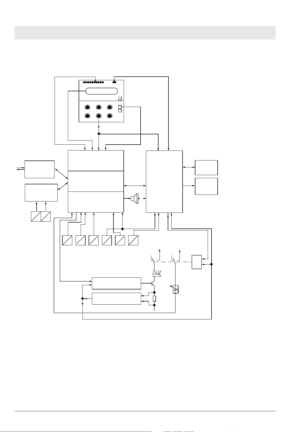
2.3 Block Diagram of the Babylog 8000/ Babylog 8000 plus/Babylog 8000 SC
LEDs 2 red Alarm LEDs
Communication
Flow
Babylog 8000
Babylog 8000 plus
EVE
V
Flow sensor
LC display
E
P
AIR
P
EL display (Babylog 8000/
Babylog 8000 plus)
Front
CPU (Master)
I/O
E
P
PO2
E
P
Potentiometer
keys
E
E
Pinsp
O
P
O2-SensorPexsp
E
O
24 Ventile
Monitoring
+27 V
Battery
Reserve
horn
+5 V
&
Valve amplifier
PEEP/PIP valve
Valve monitoring
Fig. 3: Block Diagram of the Babylog 8000/Babylog 8000 plus/Babylog 8000 SC
16
Dräger Medical AG & Co. KGaA 6173.3
_ _Printed on_18.05.05_F61733XXT01.fm
All rights reserved. Copyright reserved.
Page 19

Function description Babylog 8000
3 Airway Monitoring
In the ventilation modes IPPV/IMV and CPAP, the airway pressure (Paw), the flow at the Y-piece V
(Babylog 8000/Babylog 8000 plus), and the fraction of inspired O
(FiO2) are measured.
2
T
Depending on the selected mode and the menu settings, the parameters are monitored and displayed on
the screen. Pressure and flow curves as well as their storage can be displayed graphically on the LC
display or EL display. In all ventilation modes, the chronological sequence of the airway pressure (Paw) is
displayed in the LED bargraph.
3.1 Airway Pressure
Two internal pressure sensors measure the pressure at the inspiratory outlet (Pinsp) and the pressure at
the expiratory inlet (Pexp). The airway pressure is calculated as follows:
Paw = Pinsp – 0.7 (Pinsp – Pexp)
The following pressures are calculated from the Paw pressure signal:
Peak pressure (Peak)
Mean airway pressure (Pmean)
Positive end-expiratory pressure (PEEP)
The peak pressure is the maximum positive pressure of the most recent respiratory cycle. After 30 s, at
the latest, a new respiratory cycle must be recognized and a new measured value for the peak pressure
must be generated, otherwise the current measured value is no longer valid and is removed from the
display.
The mean airway pressure is the initial value of a software digital filter.
The PEEP is either the pressure value during the expiratory phase at a zero expiratory flow or the last
measured value before the next inspiration. Like the peak pressure, the PEEP is no longer valid after 30 s
and is removed from the display if a new measured value is not generated within the 30-s period.
3.2 Trigger Signal
In order to generate a trigger signal, the inspiratory flow must be integrated during spontaneous breathing
and compared to the adjustable trigger threshold.
3.3 Measurement of the Fraction of Inspired O
A O2 sensor in the inspiration line measures the O2 content of the respiratory gas.
Calibration data of the O
out of operation for more than 24 hours, a calibration will automatically be carried out upon power-on.
sensor is maintained after switching off the Babylog. If the Babylog has been
2
2
The operator may also initiate a calibration manually, e.g. as required after replacing an O
All rights reserved. Copyright reserved.
_ _Printed on_18.05.05_F61733XXT01.fm
Dräger Medical AG & Co. KGaA 6173.3
sensor.
2
17
Page 20

Function description Babylog 8000
A two-step calibration with 21% and 100% O2 is always carried out in order to achieve a higher
measurement accuracy over the whole concentration range and/or to be able to recognize a spent sensor
cell.
The calibration procedure is described under section "4 Monitoring Functions".
If the O
field of the screen by the flashing indication "FiO
measurement fails, the Babylog generates an alarm. This alarm status is shown in the status
2
".
2
3.4 Patient Flow (Babylog 8000/Babylog 8000 plus)
A direction-sensitive hot-wire flowmeter integrated into the Y-piece measures the inspiratory and
expiratory flows through the tube. This measurement function must be reactivated each time after
switching on Babylog 8000/Babylog 8000 plus and after each replacement of the sensor by calibrating the
sensor. The flow signal is used to calculate the following values:
Tidal volume (V
Minute volume (MV)
Percentage of the MV uptake through spontaneous breathing
Tube leakage
The tidal volume is the expiratory flow signal applied between two breathing phase cycles.
Unlike the tidal volume, the minute volume is not related to a respiratory cycle. In the same way the
inspiratory MV is calculated for leak rate detection. The expiratory minute volume is displayed. In addition
to the complete minute volume, Babylog also calculates the expiratory minute volume uptake through
spontaneous breathing.
)
T
Babylog calculates the percentage by comparing the total minute volume and the minute volume uptake
through spontaneous breathing:
spont. = (MVspontaneous/MV)
100%
*
The leakage at the tube can be estimated by comparing the inspiratory and the expiratory minute volume.
The leakage at the tube L is calculated as follows:
L= (MVinsp
_
MVexp)/(MVinsp + MVexp) * 100.
The respiratory rate f is measured through the inspiratory respiratory phase cycles.
All measured values derived from the patient flow become valid only after successful calibration of the
flow sensor.
If the flow sensor or the measuring electronics fails, an alarm is generated. However, Babylog can still be
used without the functions depending on the flow measurement. This alarm status is shown in the status
field of the screen by the flashing indication "flow".
_ _Printed on_18.05.05_F61733XXT01.fm
All rights reserved. Copyright reserved.
18
Dräger Medical AG & Co. KGaA 6173.3
Page 21

Function description Babylog 8000
4 Monitoring Functions
The system checks whether limit values are kept and all functions are ok. If a function fails or if the limit
values are not met, Babylog will generate an alarm.
4.1 Fraction of inspired O2 (FiO2)
4.1.1 O2 Measurement
The measured O
automatically set at ±4 vol.% below the set FiO
when the set value (O
value is checked against upper and lower limit values. The alarm limits are
2
value. A time delay makes sure no alarm is activated
2
) is changed or when the O2 sensor is calibrated.
2
The absolute sensor voltages are checked. The differential voltage between the two sensor cells must be
lower than (U1 + U2)/8 +1 mV. The output voltage of each individual cell must be between 9.5 mV and
123.6 mV.
4.1.2 O
The O
Calibration
2
sensor is either automatically calibrated 24 hours after the last calibration or manually after
2
selection from the mode menu.
If the O
sensor is replaced during operation the new O2 sensor will be calibrated automatically. However,
2
Babylog cannot detect a sensor replacement if the unit is switched off. In this particular case, the operator
has to calibrate the new O
sensor manually.
2
By switching over a valve the sensor is separated from the respiratory gas flow and purged with the
calibration gas (O
). This leads to a change in concentration at the O2 sensor. This change in
2
concentration allows the Babylog to recognize the activation of the calibration valve.
The calibration valve is deactivated as soon as the calibration is completed.
A two-step calibration with 21% O
and 100% O2 is carried out in order to achieve a higher measurement
2
accuracy over the whole concentration range and to be able to recognize a spent sensor cell.
During the calibration procedure the microprocessor system processes (synchronizes) one of the two O
sensor channels. The O
channels are then submitted to a specific sequence of states controlled by one
2
of the microprocessor systems and monitored for correct sequence and maximum period by the other. For
instance, searching of the calibration values for 21% or 100% must not last longer than 3.5 minutes each.
The calibration value for 21% must be between 9.2 mV and 26 mV, and for 100% between 43.6 mV and
123.6 mV; this applies to both channels. The zero voltage resulting from both values must be between
–6 mV and +6 mV.
After calibration is completed, the software checks whether the limit values respond correctly.
Calibration stops if a control gas fails.
All rights reserved. Copyright reserved.
_ _Printed on_18.05.05_F61733XXT01.fm
Dräger Medical AG & Co. KGaA 6173.3
2
19
Page 22
Function description Babylog 8000
4.2 Gas Supplies
The current measured values of the O2 and AIR gas supplies are considered when the valve bank is
adjusted. The inlet pressure for O
If the pressure falls below the limit value, a visible and audible alarm is generated. The operator is
informed about the cause of the alarm by a plain text message on the display. If the adjusted O
concentration is 21% or 100%, only an advisory message (no alarm) is displayed if the non-added gas
type fails.
If the pressure exceeds the limit value, the safety venting mechanism is activated and the continuous flow
is switched off. The Babylog will continue to operate only when the pressure has decreased to a
permissible level.
and AIR is 1.7 bar.
2
2
If the AIR supply fails, the Babylog control switches to O
supply. If the O2 supply fails, Babylog switches
2
to AIR supply.
4.3 Airway Pressure Monitoring
Depending on the selected mode and parameter settings, a certain airway pressure time profile is set. If
the actual profile deviates from the set profile, the Babylog generates an alarm.
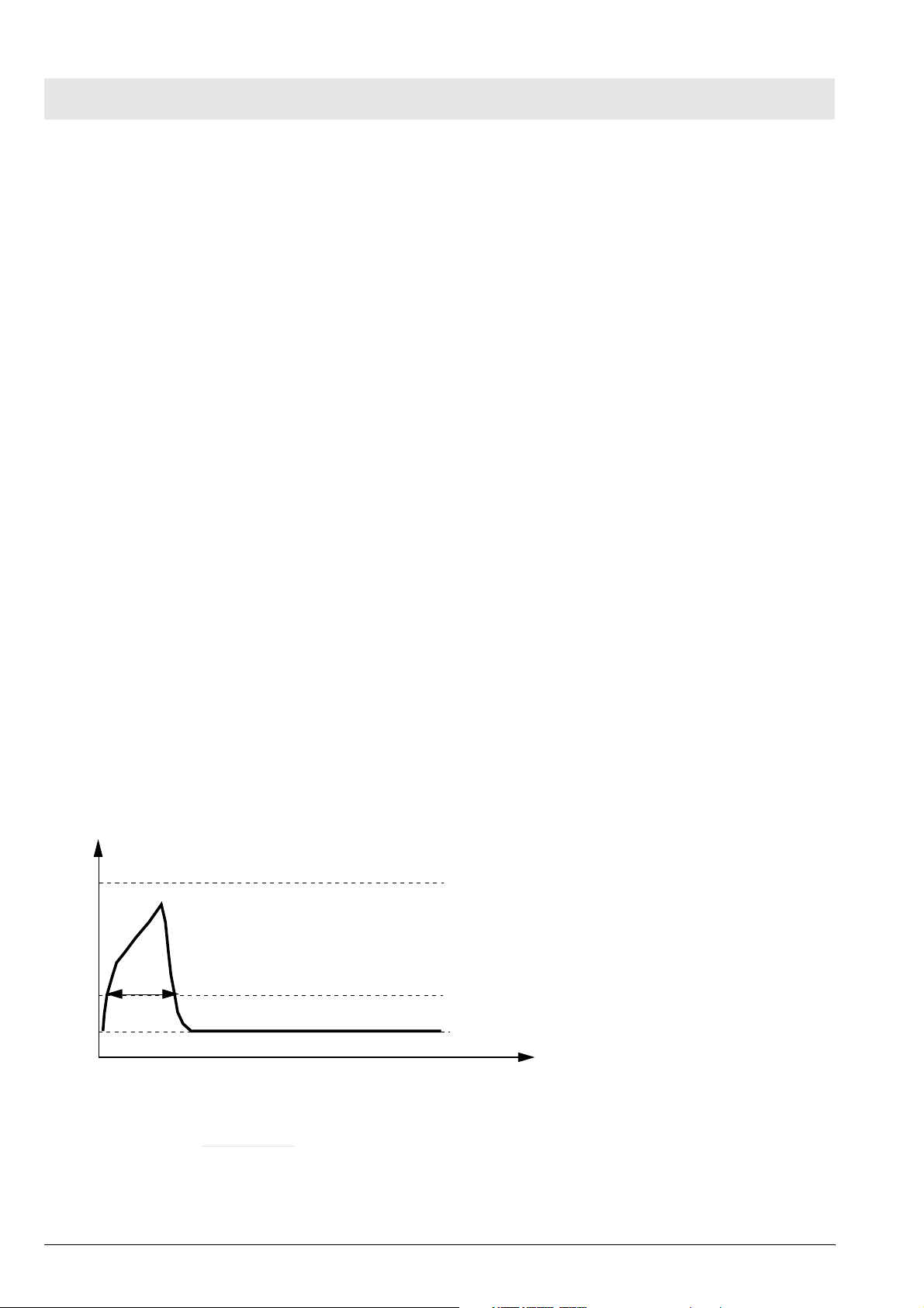
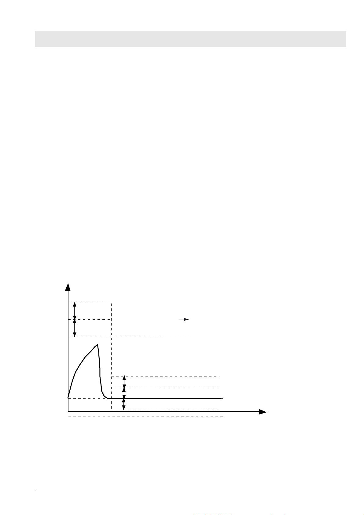
4.4 Disconnect Monitoring
Babylog recognizes whether or not the hose system has been connected correctly. If the hose system has
been connected incorrectly, the continuous flow is (partly) directed to atmosphere. No pressure builds up
in the hose system. Babylog checks during each breathing cycle whether a sufficiently high pressure is
available during inspiration. Since inspiratory breaths occur in the mandatory ventilation modes
IPPV/IMV, SIPPV and SIMV, this monitoring does not function in the CPAP mode.
Paw
Pinsp
Tdis
Pdis
PEEP
Tdis > 25 ms !
Pdis =
Pinsp - PEEP
4
Fig. 4: Disconnect Monitoring
20
Dräger Medical AG & Co. KGaA 6173.3
+ PEEP
time
Zeit
_ _Printed on_18.05.05_F61733XXT01.fm
All rights reserved. Copyright reserved.
Page 23
Function description Babylog 8000
During each mandatory breath, the level of the disconnection pressure (Pdis) must be exceeded without
interruption for at least the disconnection time (Tdis), otherwise an alarm will be generated. Pdis is a
function of the settings Pinsp and PEEP. If Pinsp is set considerably higher than the actually attained
pressure, the Pdis alarm level likewise increases.
Depending on the flow and the inspiration time settings, the level might not be attained any more.
Babylog 8000 generates an alarm even if there is no leakage in the breathing system.
4.5 Overpressure and Low Pressure Alarms
During the inspiratory and expiratory phases, the airway pressure (Paw) must not exceed the set pressure
limit by more than 10 mbar. If the set pressure limit is exceeded by 10 mbar to 20 mbar, Babylog
generates an alarm and, at the same time, reduces the inspiratory breath time. The remaining time is
added to the CPAP phase. If the set pressure limit is exceeded by more than 20 mbar, an alarm is
activated and the breathing system is vented.
In the CPAP phase, the airway pressure must be
r4 mbar of the set PEEP/CPAP. Otherwise an alarm will
be generated. If the limit is exceeded by more than 10 mbar, venting is carried out as during the
inspiratory phase even if the pressure falls below the absolute level of —2 mbar.
These overpressure and low pressure alarms apply to all ventilation modes.
4.5.1 Babylog 8000 up to Software Version 3.0
Paw
Stenose 2 (Notentlüftung)
10 mbar
Stenose 1 (Inspiration Exspiration)
10 mbar
Pinsp
6 mbar
Entlüftung
PEEP
4 mbar
4 mbar
-2 mbar
Zeit
time
Fig. 5: Alarms
4.5.2 Dynamic Stenosis Limit
The dynamic stenosis limit applies to Babylog 8000 units with software version 4.0 and Babylog 8000 SC
All rights reserved. Copyright reserved.
_ _Printed on_18.05.05_F61733XXT01.fm
Dräger Medical AG & Co. KGaA 6173.3
21
Page 24

Function description Babylog 8000
units with software version 1.0.
The limit value is (Pinsp + 5 mbar).
If this limit value is exceeded, the microprocessor system reads in the actual measured value at 8.3-ms
intervals (sampling frequency). The limit value (Pinsp + 5 mbar) is subtracted from each of the actual
measured values and entered in a summer.
As soon as the sum of 40 mbar (stenosis 1) is reached, Babylog switches over from inspiratory phase to
expiratory phase. If a sum of 70 mbar is reached, despite of the safety measure (stenosis 1), the system
will carry out an emergency venting.
Paw
Σ = 40 mbar Stenose 1
Σ = 70 mbar Stenose 2
Pinsp + 5 mbar
Pinsp
PEEP
Fig. 6: Dynamic stenosis limit
8,3
8,3
8,3 ms
time
Zeit
22
Dräger Medical AG & Co. KGaA 6173.3
_ _Printed on_18.05.05_F61733XXT01.fm
All rights reserved. Copyright reserved.
Page 25

Function description Babylog 8000
4.6 Minute Volume Monitoring (Babylog 8000/Babylog 8000 plus)
The abbreviation MV (for minute volume) is used in the following text.
4.6.1 Babylog 8000 with Software Versions 2 and 3
The monitoring menu is used to set the upper and lower alarm limits in the range of 0.03 L/min to
15 L/min. The upper and lower alarm limits are continuously compared with the measured MV value. If the
value exceeds the upper alarm limits or falls below the lower alarm limit, the system will activate an alarm.
Monitoring is deactivated during calibration of the flow sensor (Babylog 8000) to allow the measured MV
value to stabilize. If the flow measurement system fails, the MV monitoring becomes ineffective.
4.6.2 Babylog 8000 Software with Version 4.0 or Higher
The monitoring menu is used to set the upper and lower alarm limits in the range of 0.00 L/min to
15 L/min. The upper and lower alarm limits are continuously compared with the measured MV value. If the
value exceeds the upper alarm limits or falls below the lower alarm limit, the system will activate an alarm.
Monitoring is deactivated during calibration of the flow sensor (Babylog 8000) to allow the measured MV
value to stabilize. If the flow measurement system fails, the MV monitoring becomes ineffective.
4.6.3 Babylog 8000 plus
Babylog 8000 plus has the software 5.n.
4.7 Audible Alarm Generator Monitoring
Babylog has two audible alarm generators (loudspeaker and piezo). During normal operation, the
loudspeaker is the audio interface to the operator in the event of alarms. The piezo is only used in the
event of power or loudspeaker failure.
At the end of the self-test, the loudspeaker is triggered with a test signal. This test signal is monitored with
a microphone. If there is no feedback, Babylog generates error 817.
4.8 Operating Voltage Monitoring
During operation, Babylog uses comparators to continuously monitors whether the operating voltages are
within specified limits.
When Babylog is switched on, these comparators are checked by a defined changing of the comparator
reference voltage.
4.9 Rotary Potentiometer Monitoring
Input via rotary potentiometers are processed by two channels. Two microprocessor systems read the
input via independent channels and compare the results.
All rights reserved. Copyright reserved.
_ _Printed on_18.05.05_F61733XXT01.fm
Dräger Medical AG & Co. KGaA 6173.3
23
Page 26

Function description Babylog 8000
4.10 ROM Test
During operation, the ROM area used is summed up per byte in a long word variable (long word = 32 bits)
which is compared to the check sum stored in the ROM. If the check sums do not match, an error
message will be displayed.
4.11 RAM Test
During operation the RAM area used is tested with a simple algorithm. By writing 55 hex or AAhex in each
cell every bit is checked for settability and resettability.
4.12 Temperature Monitoring
A temperature sensor measures the internal temperature of the Babylog. If the temperature is not within
the range of –20 °C to 75 °C, an alarm will be generated. If the temperature is too high, a message will
inform the operator about a possible failure of the fan.
4.13 Relay and Valve Monitoring
An excess-current monitoring function is integrated into the trigger electronics of the valves. The excesscurrent monitoring function is tested after switching on Babylog. If a valve is switched on and operated
with the operate voltage for an excessive period of time, the excess-current monitoring function responds
within a specific time.
The relay which enables de-energizing of the whole pneumatics assembly is also tested once after poweron. For this purpose, the relay is switched on and off once and the voltages at the relay contact are
measured.
During operation, the system checks whether the voltage at the relay contact corresponds to the switching
condition.
4.14 Battery Monitoring
Babylog has a rechargeable Nicd battery for power failure alarms.
The battery is recharged automatically during operation and its charge checked periodically.
An error message is displayed if the voltage is too high or too low.
4.15 Flow Measurement Monitoring (Babylog 8000/ Babylog 8000 plus)
During operation, the flow sensor is checked for correct functioning, freedom of damage and intact
contacts.
24
Dräger Medical AG & Co. KGaA 6173.3
_ _Printed on_18.05.05_F61733XXT01.fm
All rights reserved. Copyright reserved.
Page 27
Function description Babylog 8000
5 Alarms, Cautions and Advisory Messages
The alarm structure of the Babylog has three priority levels:
Alarm - Immediate action required.
Caution - Checking required.
Advisory - Information for the operator.
The priority level is indicated by the different tone sequences of the individual audible alarm.
5.1 Message Display
When an alarm occurs the corresponding message is displayed as plain text message in a window of the
display. The message can be canceled momentarily by pressing the Reset/Check key (or OK key as of
software version 5.n). After a certain time out, the message appears again if its cause still exists.
If several alarms have occurred simultaneously, the highest-level alarm is shown on the display. Other
alarms will be queued. A message whose cause no longer exist will not be displayed any more.
5.2 Display and Menu
The display shows parameters and text messages. The functions of Babylog are set with keys and
potentiometers.
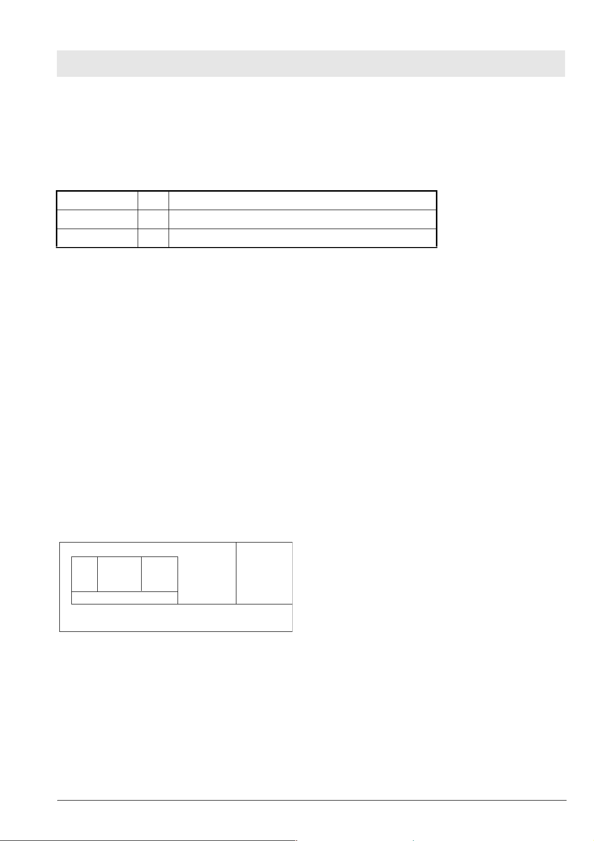
The screen is separated into different areas:
Grafic field
Menü line
Measurement
field
Fig. 7: Screen display structure
Status field
The graphics field displays real-time curves.
The measured-value field displays monitoring parameter in digital representation.
The status field displays the operating mode and other status information.
The menu line displays the current function of the keys below the screen.
In some cases, the graphics and measured-value fields are combined to form one large field.
All rights reserved. Copyright reserved.
_ _Printed on_18.05.05_F61733XXT01.fm
Dräger Medical AG & Co. KGaA 6173.3
25
Page 28

Function description Babylog 8000
5.2.1 Babylog 8000/Babylog 8000 SC with LC Display
The Monitoring/Mode key and the six keys below the LC display are used for the menu. The
Monitoring/Mode key toggles between the two main menus, the monitoring menu and the mode menu.
This works from any menu status always reaching the basic status of the other main menu. The function
of the keys depends on the respective menu status and is indicated in the menu line of the display by an
abbreviation or a symbol.
5.2.2 Babylog 8000/Babylog 8000 plus with EL Display
The key "Vent. Mode" activates the menu for the ventilation modes. The key "Vent. Option" activates the
menu for the additional functions of the ventilation modes.
26
Dräger Medical AG & Co. KGaA 6173.3
_ _Printed on_18.05.05_F61733XXT01.fm
All rights reserved. Copyright reserved.
Page 29

Function description Babylog 8000
6 Function of the Control Elements
The control elements comprise the potentiometers (rotary knobs) and the keys.
6.1 Potentiometers (Rotary Knobs)
6.1.1 Fraction of inspired O2 (O2 vol.%)
This potentiometer is used to set the fraction of inspired O
to a value between 21 vol.% and 100 vol.%.
2
The adjusted value becomes effective immediately.
6.1.2 Inspiratory time (T
)
I
This potentiometer is used to set the inspiratory time to a value between 0.1 s and 2 s. The adjusted value
becomes effective at the end of the current respiratory cycle.
6.1.3 Expiratory time (T
)
E
This potentiometer is used to set the expiratory time to a value between 0.2 s and 30 s. The adjusted
value becomes effective at the end of the current respiratory cycle.
6.1.4 Inspiratory flow (Insp. Flow)
This potentiometer is used to set the inspiratory flow to a value between 1 L/min and 30 L/min. The
adjusted value becomes effective immediately.
6.1.5 Inspiratory pressure limit (P
insp
)
This potentiometer is used to set the inspiratory pressure limit to a value between 10 mbar and 80 mbar.
A value above 40 mbar must be confirmed by pressing the Reset/Check key (or OK key as of software
version 5.n). A message is displayed. This pressure limit is also effective when a manual breath is
applied. The adjusted value becomes effective immediately.
6.1.6 PEEP/CPAP
This potentiometer is used to set the end-expiratory pressure for controlled ventilation or to set the
continuous positive airway pressure for spontaneous breathing to a value between 0 mbar and 15 mbar
(or 25 mbar as of software version 4.n). A value above 8 mbar must be confirmed by pressing the
Reset/Check key (or OK key as of software version 5.n). A message is displayed. The adjusted value
becomes effective immediately.
All rights reserved. Copyright reserved.
_ _Printed on_18.05.05_F61733XXT01.fm
Dräger Medical AG & Co. KGaA 6173.3
27
Page 30

Function description Babylog 8000
6.2 Keys
6.2.1 CPAP
Pressing this key will activate the CPAP mode. The current respiratory cycle is stopped before a new
mode becomes active (for example, IPPV/IMV). This key is protected against unintentional operation by a
software-controlled locking. After power-on, Babylog will automatically enter the most recent mode
selected.
6.2.2 IPPV/IMV (CMV) (up to software version 4.n)
Pressing this key will activate the controlled ventilation mode. This key is protected against unintentional
operation by a software-controlled locking. If CPAP was set before, the first mandatory breath is applied
after the last expiratory phase has been completed (zero expiratory flow) or after a zero flow has been
measured at the Y-piece for one second.
The CPAP and IPPV/IMV keys deactivate each other. The selected ventilation mode is indicated by a
green LED on the respective key.
6.2.3 Man. Insp.
Pressing this key will apply a breath at the set inspiratory flow rate and the set pressure limit (Pinsp). This
breath is stopped when the key is released or when a fixed time limit of 5 s is reached. The next manual or
mandatory breath can only be applied after an expiratory phase (IPPV/IMV) has been completed. If a
manual breath is stopped by the time limit, the next mandatory or manual breath can only be applied after
a fixed time-out (5 s).
6.2.4 2-min Silence
Pressing this key will silence the audible alarm for 2 minutes. This status is indicated by the yellow LED
on the key. Pressing the key again within the silence time will reactivate the audible alarm.
6.2.5 Reset/Check (OK)
Pressing the Reset/Check key (or OK key as of software version 5.n) will confirm or cancel text messages
shown on the display. The message currently shown on the display will be cancelled and the audible
alarm will be silenced.
Pressing the key for a longer period of time (approx. 2 s) will start a display test and an audible alarm
generator test.
6.2.6 Backlight On/Off (Babylog 8000/8000 SC with LC Display)
Pressing this key will switch the LCD backlight on or off.
28
Dräger Medical AG & Co. KGaA 6173.3
_ _Printed on_18.05.05_F61733XXT01.fm
All rights reserved. Copyright reserved.
Page 31

Function description Babylog 8000
6.2.7 "Cal. Config." (as of software version 5.n)
Pressing this key will activate the calibration mode.
6.2.8 Keys
The keys below the display have no fixed function. Their function depends on the operating status of the
menu.
Additional Key on the Operator Panel
This key has not been assigned a function yet. It is reserved for future extensions.
All rights reserved. Copyright reserved.
_ _Printed on_18.05.05_F61733XXT01.fm
Dräger Medical AG & Co. KGaA 6173.3
29
Page 32

Function description Babylog 8000
7 Cold Start/Warm Start Behavior
A distinction is made between an intentional switch-off with the power switch and a power failure. If a
power failure is recognized, the position of the low voltage contacts of the power switch is evaluated.
7.1 Cold-Start Behavior
When Babylog is switched off, all set parameters and data on the power switch state are stored. When
switching on the Babylog, this information is reloaded and a "cold start" is carried out. Babylog initializes,
carries out its function tests, indicates the results of these tests, and starts ventilation.
7.2 Warm-Start Behavior
A "warm start" is carried out after a power failure. Babylog does not carry out a self-test, but starts
ventilation immediately. It continues to work with the previously set parameters. A visible and audible
alarm is active during power failure.
30
Dräger Medical AG & Co. KGaA 6173.3
_ _Printed on_18.05.05_F61733XXT01.fm
All rights reserved. Copyright reserved.
Page 33

Function description Babylog 8000
8 Description of Pneumatic Functions
8.1 Gas Supplies
AIR and O2 flow through the filters F 1.1 and F 1.2 and the check valves D 1.1 and D1.2 to the pressure
regulators DR 1.1 and DR 1.2 which regulate the gases to a constant system pressure.
From the pressure regulators DR 1.1 and DR 1.2 the gases flow to the mixing and flow-control unit. The
gas mixture created there flows through the inspiratory line to the patient.
AIR and O
are taken downstream of the pressure regulators DR 1.1 and DR 1.2 and delivered to the
2
solenoid Y 1.1. If one of the gases fails, this solenoid switches over to the other one.
If the power supply is interrupted or if a stenosis 2 situation has occurred, solenoid Y 1.2 switches over to
emergency venting.
The gas for O
calibration flows through solenoid Y 1.3.
2
The gas required to control the ejector flows through solenoid Y 1.4.
F1.1
AIR
DR1.1
1
To mixing and flow-control unit
D1.1
DR1.2
2
To mixing and flow-control unit
O
D1.2
2
F1.2
Y1.1
Y1.5
Y1.2
6
Y1.3
3
4
Y1.4
5
Fig. 8: Compressed-gas connection
All rights reserved. Copyright reserved.
_ _Printed on_18.05.05_F61733XXT01.fm
Dräger Medical AG & Co. KGaA 6173.3
31
Page 34

Function description Babylog 8000
8.2 Controlled Ventilation
A continuous flow of gas is delivered to the Y-piece through the inspiratory line. The fraction of inspired O
is measured at the O
sensor S 3.1 through the open pneumatic valve Y 3.1. Safety valve Y 3.3 prevents
2
overpressure in the ventilation system, for example, if the expiratory line is blocked.
F3.1
D3.1
Y3.2
S3.1
Y3.3
Insp.
Y3.1
R3.1
3a
10 11a
Fig. 9: Inspiratory Block
8.2.1 Inspiration
2
The PEEP control valve 4 triggers the expiratory valve Y 5.1 causing it to close the expiratory side. The
continuous flow of gas is delivered to the patient’s lung. The airway pressure is measured by the two
relative pressure sensors S 6.3 and S 6.4. The inspiratory pressure limit is controlled by expiratory valve
Y 5.1.
E
P
E
P
S6.3
S6.4
6 Pressure
measurement
R1.1
Y4.1
Y5.1
4 PEEP/PIP valve
5 Expiratory valve
Fig. 10: Expiratory valve, PEEP/PIP valve, and pressures measurement
32
Dräger Medical AG & Co. KGaA 6173.3
_ _Printed on_18.05.05_F61733XXT01.fm
All rights reserved. Copyright reserved.
Page 35

Function description Babylog 8000
8.2.2 Expiration
The PEEP control valve Y 4.1 vents the control pressure at the expiratory valve Y 5.1. The expiratory
valve Y 5.1 opens the ventilation system. Expiration takes place through the open expiratory valve Y 5.1.
The ejector, which is driven through the open solenoid Y 1.4, supports expiration.
6 Pressure measurement
From
Y1.4
R1.1
E
P
E
P
S6.3
S6.4
Y4.1
Y5.1
4 PEEP/PIP valve
5 Expiratory valve
Fig. 11: Venting
8.2.3 PEEP
The PEEP/PIP valve is a pressure regulating valve which generates a control pressure of -19 mbar to
+80 mbar. Control pressures are used to trigger the inspiratory and expiratory valves in order to deliver
the peak inspiratory pressure (PIP) during inspiration and the positive end-expiratory pressure (PEEP)
during expiration to the patient-side valves.
An ejector integrated into the valve allows a negative control pressure of up to -19 mbar.
8.2.4 CPAP
The control pressure generated by the PEEP control valve Y 4.1 acts on the control side of the expiratory
valve Y 5.1 and builds up a continuous positive airway pressure in the ventilation system.
All rights reserved. Copyright reserved.
_ _Printed on_18.05.05_F61733XXT01.fm
Dräger Medical AG & Co. KGaA 6173.3
33
Page 36

Function description Babylog 8000
9 Measurement of the Ventilation Parameters
9.1 O
Measurement
2
The O2sensor continuously measures the fraction of inspired O2through the open pneumatic valve Y 3.1.
F3.1
D3.1
Y3.2
S3.1
Y3.3
Insp.
Y3.1
R3.1
3a
Fig. 12: Measurement of the fraction of inspired O
10 11a
.
2
An automatic two-step calibration is carried out at 24-hour intervals.
AIR is supplied to the pneumatic valve Y 3.1 through solenoids Y 1.1, Y 1.2, and Y 1.3. The pneumatic
valve Y 3.1 closes the connection between the O
valve Y 3.2 is opened while, at the same time, the O
sensor S 3.1 and the inspiratory line. The pneumatic
2
sensor is purged with AIR through the restrictor
2
R 3.2 for approximately 2.5 minutes.
Then, purging with O
is carried out in the same way. After calibration, the solenoid Y 1.1 switches back to
2
AIR, the solenoid Y 1.3 closes, the pneumatics valve Y 3.2 closes, too, and the pneumatics valve Y 3.1
reconnects the O
sensor to the inspiratory line.
2
9.2 Measurement of the Airway Pressure
Due to the continuous flow, the inspiratory measurement results in a value that is higher than the value
measured at the Y-piece. Since an expiratory measurement results in a value which is too low, an
average value is calculated from the measured values of the relative pressure sensors and displayed on
the screen.
A bactericidal metering pipe prevents contamination of the pressure sensor with expiratory gas.
34
Dräger Medical AG & Co. KGaA 6173.3
_ _Printed on_18.05.05_F61733XXT01.fm
All rights reserved. Copyright reserved.
Page 37

Function description Babylog 8000
9.3 Pneumatics Control PCB
The Pneumatics Control PCB is the output unit of the CPU 68000. It receives serial data from the I/O PCB
and triggers the corresponding valves.
Further functions of Pneumatics Control PCB: voltage supply to the patient system heater, power supply
to the PEEP/PIP valve.
Motherboard
Control
signals
Seriel parallel converter
Relay
control
Input logic
Pneumatic analog PCB
Current and amplifier monitoring
Output
Valve
voltage
PEEPvoltage
PEEP
valve
Valve block AIR
Valve block O2
Fig. 13: Block diagram of the Pneumatics Control PCB
All rights reserved. Copyright reserved.
_ _Printed on_18.05.05_F61733XXT01.fm
Dräger Medical AG & Co. KGaA 6173.3
Input block
Pneumatic
35
Page 38

Function description Babylog 8000
9.4 Pneumatics Analog PCB
The Pneumatics Analog PCB controls and monitors the operate voltage and the withstand voltage to the
valves. The Pneumatics Analog PCB is installed on the Pneumatics Control PCB.
Current of
the valve
Current control
Amplifier control
Fig. 14: Block diagram of the Pneumatics Analog PCB
+ Ref.
Valve voltage
+ Ref.
State of valve
Switch
regulator
Fig. 15: Block diagram of the Pneumatics Analog PCB
Stop clock
_ _Printed on_18.05.05_F61733XXT01.fm
All rights reserved. Copyright reserved.
36
Dräger Medical AG & Co. KGaA 6173.3
Page 39

Function description Babylog 8000
9.5 Patient System Heater
The patient system heater consists of a heating resistor located at the expiratory-valve connection.
9.6 Pressure Sensor Base PCB
The Pressure Sensor Base PCB has four pressure sensors for the measurement of
O
supply pressures and for coordination of the pressure and the O2 measurement signals.
2
Pinsp
9.7 O2 Amplifier PCB
The O2 Amplifier PCB amplifies the sensor signals directly at the sensor.
, P
exp
, AIR and
All rights reserved. Copyright reserved.
_ _Printed on_18.05.05_F61733XXT01.fm
Dräger Medical AG & Co. KGaA 6173.3
37
Page 40

Function description Babylog 8000
10 Components of the Electronic Assembly
The electronic assembly consists of the following printed circuit boards and subassemblies:
Power supply unit
Motherboard PCB
CPU 68000 PCB
I/O PCB
Flow PCB (Babylog 8000) (optional)
Monitoring PCB/Watchdog PCB
Front Adapter PCB
Front Controller PCB (Babylog 8000/Babylog 8000 SC with LC display )
Front PCB (Babylog 8000/Babylog 8000 plus with EL Display)
Display PCB (Babylog 8000/Babylog 8000 SC with LC display )
EL display (Babylog 8000/Babylog 8000 plus with EL display)
Potentiometer field
Display field
Communication PCB (optional)
Interface PCB (optional)
10.1 Power Supply Unit
The power supply unit supplies Babylog with the following voltages:
+5 V
+15 V
–15 V
+27 V
The power supply unit comprises the mains connection, the ON/OFF switch, and the fuses.
10.2 Motherboard PCB
All electrical connections between the individual printed circuit boards are led through the Motherboard
PCB. Cable connections go to the front panel, to the pneumatic assembly, and to the rear panel, which
contains the rechargeable battery, the fan, the loudspeaker, and the flow-sensor connection.
38
Dräger Medical AG & Co. KGaA 6173.3
_ _Printed on_18.05.05_F61733XXT01.fm
All rights reserved. Copyright reserved.
Page 41

Function description Babylog 8000
10.3 CPU 68000 PCB
The CPU 68000 PCB comprises the following components: 68000 CPU, EPROM, RAM, time-keeper
RAM, address decoder, multi function peripheral (four 8-bit timers, RS 232 interface, 8-bit I/O port),
DTACK and bus error generator, watchdog, power-on reset, interrupt controller, bus controller, and bus
interface.
The CPU 68000 PCB is clocked with 8 MHz. If the "communication" conversion kit is installed, the clock
frequency is increased to 16 MHz.
Bus-Interface
Control-Bus
Adreß-Bus
Digital-Bus 68000
Daten-Bus
Adreß-Bus
Seriell
Powerfail
I/O
Digital I/O
Status CPU
Reset
Interrupt
Power-onReset
Interrupt
Controller
BusController
Optionsschalter
Adressdecoder
EPROM
RAM
Time
Keeper
RAM
Multi
Function
Peripheral
16 MHz
8 MHz
CPU 68000
Coprozessor
DTACK-,
Bus-ErrorGenerator
Watchdog
12 MHz
Fig. 16: Block diagram of the CPU 68000 PCB
All rights reserved. Copyright reserved.
_ _Printed on_18.05.05_F61733XXT01.fm
Dräger Medical AG & Co. KGaA 6173.3
39
Page 42

Function description Babylog 8000
10.4 I/O PCB
The I/O PCB measures the analog signals O2 concentration, inspiratory pressure, expiratory pressure,
AIR supply pressure, and O
supply pressure, and triggers the loudspeaker and the PEEP/PIP valve.
2
DTACK
Control bus
Adress bus
Digital bus 6800
Data bus
I/O connections
DTACK
generator
Adress
decoder
Current of the PEEP valve
Loud speaker
seriel valve datas
Muxer
Fig. 17: Block diagram of the I/O PCB
Control-Bus
Adreß-Bus
Daten-Bus
S
&
H
PIO
Parallel/seriell
Converter
Sound
generator
D
A
D
U
A
I
40
Dräger Medical AG & Co. KGaA 6173.3
_ _Printed on_18.05.05_F61733XXT01.fm
All rights reserved. Copyright reserved.
Page 43

Function description Babylog 8000
10.5 Flow PCB (Babylog 8000/Babylog 8000 plus) (optional)
The Flow PCB in Babylog 8000/Babylog 8000 plus measures the flow. It provides the following function
blocks: sensor bridges with sensor amplifiers, analog-to-digital converter, microprocessor Z80 minimum
system, Z80-68000 bus interface.
Adress
decoder
6 MHz
DTACK
Control bus
Adress bus
Digital bus 68000
Data bus
Flow sensor
Analog 1
Analog 4
Status flow
Control bus
Adress bus
Data bus
DTACK
generator
Adress
decoder
Control bus
Adress bus
Data bus
System reset
Muxer
S
&
H
EPROM
64 k / 32 k
RAM
8 k / 2 k
Dual-PortRAM
A
Z80
CPU
Timer
Watchdog
PIO
D
Fig. 18: Block diagram of the Flow PCB
All rights reserved. Copyright reserved.
_ _Printed on_18.05.05_F61733XXT01.fm
Dräger Medical AG & Co. KGaA 6173.3
41
Page 44

Function description Babylog 8000
10.6 Monitoring PCB
The Monitoring PCB measures and monitors all measurement and status signals. The Monitoring PCB
compares these signals with the signals from the CPU 68000. If an error occurs, the Monitoring PCB
switches off the valves, activates the audible alarm generator, and resets the CPU PCB.
A Z80 microprocessor (minimum system) controls the Monitoring PCB. The Monitoring PCB
communicates with the CPU 68000 via a bus interface.
10.6.1 Measurement of Analog Signals
concentration
O
2
Potentiometers (O
Pressure P
insp
, Vinsp, TI, TE, P
2
, PEEP/CPAP)
insp
System temperature
Supply voltages (potentiometer reference, rechargeable battery, GNDA, GND reference, 27 V)
Valve voltage
10.6.2 Measurement of Digital Inputs
STATUS CPU 68000 (reset)
STATUS flow (reset)
STATUS I/O (printed circuit board is available)
STATUS valves (current and drive monitoring on the Pneumatics Analog PCB)
Powerfail
Position of power switch
10.6.3 Measurement of Digital Outputs
Alarm LEDs (2 LEDs on the Display PCB)
Flow test 1 and 2 (for Flow PCB)
Switching on of valve relays K1 and K2 (voltage supply to valves and PEEP/PIP valve on the
Pneumatics Control PCB)
CPU PCB reset
7-segment status display for error messages
Standby audible alarm generator
Loudspeaker monitoring via microphone
Battery charging and testing circuit
Test of the supply voltages +5 V, +15 V, –15 V (Display PCB)
42
Dräger Medical AG & Co. KGaA 6173.3
_ _Printed on_18.05.05_F61733XXT01.fm
All rights reserved. Copyright reserved.
Page 45

Function description Babylog 8000
DTACKQ
Control bus
Adress bus
Digital bus 68000
Data bus
Analog Input
Bus interface
S & H
(Filter)
INTQ
DTACKQ
generator
Adress
decoder
Control bus
Adress bus
Adress
decoder
EPROM
64 k
RAM
8 k
DualPor tRAM
PIO
Z80-Bus
4 MHz
Z 80
CPU
Timer
Watchdog
Watch dog
PCB
A
PIO
D
Status
display
Digital Input
I/O connections
Fig. 19: Block diagram of the Monitoring PCB
Block diagram of the Watchdog PCB of the Monitoring PCB (in new boards the Watchdog PCB is
integrated into the Monitoring PCB).
All rights reserved. Copyright reserved.
_ _Printed on_18.05.05_F61733XXT01.fm
Dräger Medical AG & Co. KGaA 6173.3
43
Page 46

Function description Babylog 8000
voltages
+
-
U
Ref
sound
decoder
Signal sound generator monitoring
rechargeable battery
Alarm LED power
Fig. 20: Block diagram of the Watchdog PCB
44
Dräger Medical AG & Co. KGaA 6173.3
_ _Printed on_18.05.05_F61733XXT01.fm
All rights reserved. Copyright reserved.
Page 47

Function description Babylog 8000
10.7 Front Adapter PCB
The Front Adapter PCB connects the CPU 68000 to the front panel. The front panels provides the control
and display elements.
The Front Adapter PCB reduces the 16-bit data bus to 8 bits, generates control signals for the front panel,
and controls the LC display (VIDEO RAM and LCD controller) or the EL display.
The power supply and the analog signals are led from the Motherboard PCB to the front panel through the
Front Adapter PCB.
DTACKQ
Control bus
Adress bus
Digital bus 68000
Data bus
DTACK
generator
Adress
decoder
Daten-Bus (16 bit)
seriell Datas to LC display
LCDController
DualPor tRAM
Adress and Control bus
Frontcontroller
Data bus (8 bit)
Ansteuerung Alarm LED
I/O connections
analog current power
Potentiometer monitoring
Fig. 21: Block diagram of the Front Adapter PCB
All rights reserved. Copyright reserved.
_ _Printed on_18.05.05_F61733XXT01.fm
Dräger Medical AG & Co. KGaA 6173.3
45
Page 48

Function description Babylog 8000
10.8 Front Controller PCB
(Babylog 8000/Babylog 8000 SC with LC Display)
The Front Controller PCB reads in the keys of the potentiometer and display field, controls the LEDs of
the potentiometer and display field, powers the LC display with operating voltage (contrast), controls the
LC display backlight, and generates the control signal for the bargraph.
Control bus
and
Adress bus
Data bus
U
B
D
A
key port
LED driver
Amplifier
Bargraph
U
Ref
Contrast adjustment of LC display
DC
AC
Test A/D converter
voltage for
display illumination
Keys of the front panel and options switches
LEDs of the front panel
LC display
Alarm LEDs
Bargraph of the front panel
A
D
6x
Adress
decoder
Potentiometer of the front panel
Fig. 22: Block diagram of the Front Controller PCB (Babylog 8000/8000 SC with LC display)
_ _Printed on_18.05.05_F61733XXT01.fm
All rights reserved. Copyright reserved.
46
Dräger Medical AG & Co. KGaA 6173.3
Page 49

Function description Babylog 8000
10.9 Front PCB (Babylog 8000/Babylog 8000 plus with EL Display)
The Front PCB reads in the keys of the potentiometer and display field, controls the LEDs of the
potentiometer and display field, powers the EL display with operating voltage (contrast), and generates
the control signal for the bargraph.
Control bus
und
Adress bus
Data bus
UB
DC
key port
LED driver
Amplifier
Bargraph
URef
+5 V, +12 V
EL display, complete
DC
EL display converter
Cable of EL display
EL display
Keys and option switches of the front panel
LEDs of the front panel
Alarm LEDs
Bargraph of the monitoring field
Test A/D-Wandler
A
D
Adress
decoder
Fig. 23: Block diagram of the Front PCB
All rights reserved. Copyright reserved.
_ _Printed on_18.05.05_F61733XXT01.fm
Potentiometer of the potentiometer field
6x
Dräger Medical AG & Co. KGaA 6173.3
47
Page 50

Function description Babylog 8000
10.10 Display PCB (Babylog 8000/Babylog 8000 SC with LC Display)
The Display PCB contains the control electronics for the LED array of the bargraph.
Data bus
Chip Select
Adress bus
RAM
Modul 06
Fig. 24: Block diagram of the Display PCB
48
Dräger Medical AG & Co. KGaA 6173.3
_ _Printed on_18.05.05_F61733XXT01.fm
All rights reserved. Copyright reserved.
Page 51

Function description Babylog 8000
10.11 EL display (Babylog 8000/Babylog 8000 plus with EL Display)
The EL display (Electro Luminescence Display) consists of the EL display, the EL display converter, and the
EL display connecting cable. The EL display displays the signals and other information. The EL display
converter generates the (200-240 V a.c.) voltage for the luminescence voltage of the EL display. The EL
display and the converter are ”matched”.
EL display
EL display connecting cable
EL display converter
Fig. 25: Components of EL display
pn 45363667
All rights reserved. Copyright reserved.
_ _Printed on_18.05.05_F61733XXT01.fm
Dräger Medical AG & Co. KGaA 6173.3
49
Page 52

Function description Babylog 8000
10.12 Potentiometer Field
The Potentiometer Field comprises the following components:
6 potentiometers (O
9 LEDs (O
vol.%, TI, TE, Insp. Flow , P
2
vol.%, TI, TE, Insp. Flow , P
2
, PEEP/CPAP, CPAP, IPPV, reserve)
insp
, PEEP/CPAP)
insp
3 keys (CPAP, IPPV, reserve) (Vent. Mode, Vent. Option, reserve as of software version 5.n
10.13 Display Field
The display field contains the following components:
11 keys (silence, reset, man./insp., menu, keys 1 to 6, light). The "light" key is only available on
Babylog 8000 with LC display. The key signals are read in via the Front Controller PCB or the Front
PCB.
LED array of the bargraph. The LED array is controlled via the Display PCB.
7 LEDs (warning (yellow), mode, monitoring, silence, triggers 1 to 3). The LEDs are controlled via the
Front Controller PCB or the Front PCB.
2 red alarm LEDs. The LEDs are controlled via the Monitoring PCB/Watchdog PCB.
50
Dräger Medical AG & Co. KGaA 6173.3
_ _Printed on_18.05.05_F61733XXT01.fm
All rights reserved. Copyright reserved.
Page 53

Function description Babylog 8000
10.14 Communication PCB
The Communication PCB controls an external printer, a computer, and an analog recorder. The
Communication PCB is equipped with an RS232 interface, two 12-bit D/A outputs, and one digital trigger
output. All outputs are electrically isolated from the electronics. Software version 3.00 or higher, a CPU
PCB with 16 MHz (the CPU PCB with 8 MHz was standard until end of 1992) and the Interface PCB with
outputs on the rear panel are minimum requirements for operation.
System connector
Analog
Output
A
D
Trigger
RS 232
Nurse call
2,5 kV electrical isolation
DTACK
Register
Parallel/seriell
converter
generator
Adress
decoder
DC
DC
MFP*
EEPROM
*MFP=Multi Function Prozessor
DTACK
Control bus
Digital bus 68000
Adress bus
Data bus
I/O connections
Fig. 26: Block diagram of the Communication PCB
All rights reserved. Copyright reserved.
_ _Printed on_18.05.05_F61733XXT01.fm
Dräger Medical AG & Co. KGaA 6173.3
51
Page 54

Function description Babylog 8000
10.15 Interface PCB
The Interface PCB is a passive printed circuit board with the following connections:
Flow-sensor cable
2 analog outputs
Trigger output
RS 232
The Interface PCB is required for the optional communication function.
+15 V
X 1 / 16
X 1 / 8
X 1 / 12
X 1 / 5
X 1 / 4
X 1 / 14
X 1 / 15
X 1 / 16
X 8 / 1
X 8 / 2
X 8 / 3
X 8 / 4
X 8 / 5
X 8 / 6
X 8 / 7
X 8 / 8
X 8 /15
X 8 / 16
V 5
V 6
V 1
V 2
+15 V
V 3
V 4
+15 V
R 1
R 1
R 1
X 4
X 5
X 6
X 3 / 2
X 3 / 3
X 3 / 5
X 3 / 7
X 3 / 8
X 3 / 4
X 3 / 6
X 3 / 1
X 7 / 1
X 7 / 9
X 7 / 2
X 7 / 10
X 7 / 3
X 7 / 11
X 7 / 4
X 7 / 12
X 7 / 8
X 7 / 15
Analog 1
Analog 2
Trigger
RS 232
Flow-Sensor
Fig. 27: Interface PCB
52
Dräger Medical AG & Co. KGaA 6173.3
_ _Printed on_18.05.05_F61733XXT01.fm
All rights reserved. Copyright reserved.
Page 55

Function description Babylog 8000
11 Sensors
11.1 Pressure Sensors
The pressure sensors function according to the piezoresistive principle. An approximately 4 mm into
4 mm silicon chip has 4 ion implanted resistors. The silicon chip is also equipped with a pressure
diaphragm.
11.2 Y-Piece with Flow Sensor (Babylog 8000/Babylog 8000 plus)
The Y-piece with integrated flow sensor is used in pediatric respiratory gas systems. This Y-piece
connects the respiratory gas hoses of Babylog 8000/Babylog 8000 plus to the patient catheter
connection.
Hot wire flowmeter
Hot wire flowmeter for
direction recognition
Inspiration
Exspiration
Fig. 28: Flow sensor
The flow sensor works according to the hot-wire flowmeter principle. It has an additional measuring wire
for direction recognition.
All rights reserved. Copyright reserved.
_ _Printed on_18.05.05_F61733XXT01.fm
Dräger Medical AG & Co. KGaA 6173.3
53
Page 56

Function description Babylog 8000
11.2.1 Measuring Principle of the Flow Measuring Bridge
The flow sensor incorporates two hot-wire flowmeters. A separate wire is used for direction recognition.
Both wires are evaluated on the Flow PCB by two separate measuring channels.
U
B
V 7
Flow test
Comparator
12 Bit
D 24
R 54
RDR
Hot wire
Hot wire
glowing
R 72
R 70
PI regulator
N 7
+
Umeß
-
Fig. 29: Principle diagram of the flow measuring bridge
The measuring bridge comprises the resistors R 54, R 72, R 70, and the measuring wire of the sensor.
The measuring wire is kept at a constant resistance. This means that the amount of heat dissipated by the
gas flow has to be readjusted. As system deviation the voltage passes through the node R 54/R72 and
the measuring wire R 70. If the voltage is adjusted to "0", the current flowing through the measuring wire
and the R70 is a measure for the heat dissipated. The controllable power source is made with V7. N7 is a
controller with PI behavior. To adjust the bridge a current can be injected via the D/A converter D 24 into
the node R54/R72. The current through the bridge is changed such that the wire begins to glow. Burning
out of the wire is prevented by a current limiter. The current limiter compares the voltages and switches
the current source off, if required. Current limitation is effected through the comparator which is connected
to the input of V7. The current through the flow measuring bridge is changed for test purposes. R 70 is a
current measuring resistor (four-wire measurement) which measures the heating current (proportional
voltage).
54
Dräger Medical AG & Co. KGaA 6173.3
_ _Printed on_18.05.05_F61733XXT01.fm
All rights reserved. Copyright reserved.
Page 57

Function description Babylog 8000
11.3 O2 Sensor
The O2 sensor is a double cell which functions according to the fuel-cell principle, that is, it is an
electrochemical cell which generates a voltage by means of an ion current. The cell consists of a capsule
which incorporates electrolytes, lead anodes and two gold cathodes with Teflon diaphragm.
cathode 1
O2
cathode 2
Fig. 30: O
sensor cell
2
-
Plastic housing
Alkali-Elektrolyt
anode
The oxygen to be measured diffuses through the Teflon diaphragm, undergoes a chemical reaction at the
gold cathode and produces lead oxide and water at the lead anode. During this chemical process an
electric voltage is generated which is proportional to the oxygen partial pressure. The gold cathodes are
negative, the lead anode is positive. The internal resistance is determined by the surface of the
electrodes, the oxygen diffusion velocity, and the distances. Under normal condition, the internal
resistance is 700 ohms.
Like most chemical processes, this process is also temperature-dependent. Therefore, compensation
resistors are connected in parallel to the sensor. These resistors correct the measuring voltage in relation
to the internal resistance. Two voltages are generated which are identical within specified tolerances. The
voltages are compared to each other. The two gold cathodes are arranged separately. The two voltages
do not influence each other. If one gold cathode fails, the other carries out the measurement. In this case,
the electronics would report a malfunction.
All rights reserved. Copyright reserved.
_ _Printed on_18.05.05_F61733XXT01.fm
Dräger Medical AG & Co. KGaA 6173.3
55
Page 58

Function description Babylog 8000
56
Dräger Medical AG & Co. KGaA 6173.3
_ _Printed on_18.05.05_F61733XXT01.fm
All rights reserved. Copyright reserved.
Page 59

Replacing Non Repairable Items
57
Page 60

58
Page 61

Replacing Non-Repairable Items Babylog 8000
1 Important Information
Follow the instructions in this manual and carefully read and observe all statements following a warning or
info symbol. If you ignore the warning statements, this may lead to personal injury and/or device damage.
Non-repairable items should only be replaced by qualified service personnel.
Before removing the rear panel, unplug the power plug from the mains supply and disconnect the device
from the central gas supply.
Observe antistatic precautions prior to and during any corrective procedure.
After performing any repair or inspection on medical devices, carry out a final check before returning the
devices to normal use.
All rights reserved. Copyright reserved.
_ _Printed on_18.05.05_GBK61733XXV01.fm
Dräger Medical AG & Co. KGaA 6173.3
59
Page 62

Babylog 8000 Replacing Non-Repairable Items
2 Cleaning or Replacing the Cooling Air Filter Every 4 Weeks
• Pull out the cooling air filter 1 from its mount in the rear panel.
• Insert a new cooling air filter or wash the old one in warm water with a few drops of dish-washing
liquid. Dry well.
• Insert the cooling air filter 1 into the mount (make sure it is free of folds).
1
Fig. 1: Cooling Air Filter
_ _Printed on_18.05.05_GBK61733XXV01.fm
All rights reserved. Copyright reserved.
60
Dräger Medical AG & Co. KGaA 6173.3
Page 63

Replacing Non-Repairable Items Babylog 8000
3 Replacing the O2 Sensor Capsule
• Remove the slotted-head screws 1 in the cover on the right-hand side and carefully pull the cover out.
• Pull the spent O
• Insert the new O
sensor capsule out of its mount.
2
sensor capsule into the mount (the ring-shaped conductors must show towards the
2
cover).
• Push the cover in place and secure it with the screws 1.
• Calibrate the O
sensor manually.
2
1
1
Fig. 2: O
Sensor Capsule
2
3.1 O2Sensor Calibration
Calibration is carried out automatically every 24 hours during operation.
Calibration should be carried out manually after replacement of the sensor capsule.
Calibration can be carried out manually at any time.
3.2 Calibrating the O2Sensor After Replacement
• Press the key 2 in the main menu.
All rights reserved. Copyright reserved.
_ _Printed on_18.05.05_GBK61733XXV01.fm
Dräger Medical AG & Co. KGaA 6173.3
61
Page 64

Babylog 8000 Replacing Non-Repairable Items
2
D
Fig. 3: Front View
The following display appears on the LCD:
S p e c i a l f u n k t i o n s
V I V E C a l
• Press the “Cal” key.
The following display appears on the LCD:
s e n s o r c a l i b r a t i o n
Flow
F i O 2
IPPV
IMV
C o n f i g
IPPV
IMV
62
Dräger Medical AG & Co. KGaA 6173.3
_ _Printed on_18.05.05_GBK61733XXV01.fm
All rights reserved. Copyright reserved.
Page 65

Replacing Non-Repairable Items Babylog 8000
• Press the “FiO2” key.
IPPV
IPPV
25 mbar
O2c a l i b r a t i o n
Meas switched off
27 %
. 0 mbar
IPPV
IMV
IMV
IMV
O2-Cal
Meas Values Trend
After approx. 5 min, the display “O2 Cal” disappears from the status field and calibration is completed.
The message in the screen can be canceled as follows:
• Press the Reset Check key.
!
3.3 Disposing of the O2 Sensor Capsule
The O2 sensor capsule is special waste. Dispose of according
to local waste disposal regulations.
All rights reserved. Copyright reserved.
_ _Printed on_18.05.05_GBK61733XXV01.fm
Dräger Medical AG & Co. KGaA 6173.3
63
Page 66

Babylog 8000 Replacing Non-Repairable Items
4 Replacing the Lip Seals Every 2 Years
• Lift the toggle 1 and take out the expiratory valve.
D
1
Fig. 4: Removing the Expiratory Valve
• Use, for example, a spherical-head 2.5 mm screwdriver to remove the old lip seals 2. Insert the new
lip seals and make sure they fit properly.
D
2 2
2
Fig. 5: Location of the Lip Seals
• Re-mount the expiratory valve. To do so, lift up the toggle and place the expiratory valve to the front
using the guide rods.
• Lock the expiratory valve with the toggle 1.
64
Dräger Medical AG & Co. KGaA 6173.3
_ _Printed on_18.05.05_GBK61733XXV01.fm
All rights reserved. Copyright reserved.
Page 67

Replacing Non-Repairable Items Babylog 8000
5 Replacing the NiCd Battery (Power Failure Alarm) Every 2 Years
• Remove the screw 1 on the fan/loudspeaker cover.
1
Fig. 6: Opening the Loudspeaker Cover
• Gently lower the cover 3.
• Disconnect the cable connection 2 and place the cover 3 aside.
• Remove the screws 4 on the battery mount.
4
4
2
3
Fig. 7: Removing the Loudspeaker Cover
All rights reserved. Copyright reserved.
_ _Printed on_18.05.05_GBK61733XXV01.fm
Dräger Medical AG & Co. KGaA 6173.3
65
Page 68

Babylog 8000 Replacing Non-Repairable Items
• Remove the battery 5 and install a new one.
5
Fig. 8: Replacing the Battery
• Re-assemble the Babylog 8000/Babylog 8000 plus/Babylog 8000 SC. The battery for power failure
alarm is recharged automatically during operation.
After replacing the battery, allow the device to operate for at least half an hour in order to sufficiently
charge the battery.
No acoustic alarm will sound in the event of power failure if
the battery is not sufficiently charged. Risk of severe injury or
death. Allow the device to operate for at least half an before
clinical application.
66
Dräger Medical AG & Co. KGaA 6173.3
_ _Printed on_18.05.05_GBK61733XXV01.fm
All rights reserved. Copyright reserved.
Page 69

Replacing Non-Repairable Items Babylog 8000
6 Replacing the Pressure Reducer Every 6 Years
• Disconnect the Babylog 8000/Babylog 8000 plus/Babylog 8000 SC from the mains supply.
• Disconnect the gas supply hoses from the central gas supply/gas cylinder.
• Disengage the Babylog 8000/Babylog 8000 plus/Babylog 8000 SC from the trolley. To do so, loosen
the knurled nuts 1 on the rear panel.
1 1
Fig. 9: Location of the Knurled Nuts
Fig. 10: Disengaging the Babylog 8000/Babylog 8000 plus/Babylog 8000 SC
All rights reserved. Copyright reserved.
_ _Printed on_18.05.05_GBK61733XXV01.fm
Dräger Medical AG & Co. KGaA 6173.3
67
Page 70

Babylog 8000 Replacing Non-Repairable Items
• Remove the screws 2 from the two side panels.
2 2 2 2
Fig. 11: Left and Right Panel
• Remove the bottom screws 3 from the fixing straps on the left and right panel.
3 3
Fig. 12: Removing the Fixing Straps
68
Dräger Medical AG & Co. KGaA 6173.3
_ _Printed on_18.05.05_GBK61733XXV01.fm
All rights reserved. Copyright reserved.
Page 71

Replacing Non-Repairable Items Babylog 8000
• Remove the bottom screws 4 from the fixing straps on the rear panel.
4
Fig. 13: Rear Panel of the Babylog 8000/Babylog 8000 plus/Babylog 8000 SC
• Gently lift the top part and place it next to the bottom part.
• Remove the screws 5.
• Remove the gas supply connection plate 6.
• Remove the two filters and the gasket. Loosen the screws 7 on the supply block.
77
55
7 7
Fig. 14: Supply Block
All rights reserved. Copyright reserved.
_ _Printed on_18.05.05_GBK61733XXV01.fm
Dräger Medical AG & Co. KGaA 6173.3
6
69
Page 72

Babylog 8000 Replacing Non-Repairable Items
• Slightly tilt the supply block 8. Make sure not to damage the hoses or the printed circuit boards.
8
Fig. 15: Pneumatic Assembly of the Babylog 8000/Babylog 8000 plus/Babylog 8000 SC
Tilting the supply block excessively will cause damage to the
hoses and/or printed circuit boards. Do not tilt the supply
block more than necessary.
70
Dräger Medical AG & Co. KGaA 6173.3
_ _Printed on_18.05.05_GBK61733XXV01.fm
All rights reserved. Copyright reserved.
Page 73

Replacing Non-Repairable Items Babylog 8000
• Remove the fastening screws 9 from the pressure reducers.
• Pull out the pressure reducers.
9 9 9 9
Fig. 16: Supply Block
• Replace the pressure reducers 10 for AIR and O
12 (part number M23154).
10
11
Fig. 17: Pressure Reducers
including the O-rings 11 (part number D19080) and
2
12
• Mount the pressure reducers onto the supply block.
• Mount the supply block.
• Re-insert the gasket and the filters (wire fabric side shows towards inside).
• Mount the gas supply connection plate.
All rights reserved. Copyright reserved.
_ _Printed on_18.05.05_GBK61733XXV01.fm
Dräger Medical AG & Co. KGaA 6173.3
71
Page 74

Babylog 8000 Replacing Non-Repairable Items
• Unlock the pressure reducers by pulling the adjusting rings 1 in direction of A.
• Turn the adjusting rings 1 counterclockwise in direction of B as far as they will go (pressure reducers
will be closed).
A
Air
B
1
O2
Fig. 18: Pneumatic Assembly
• Connect to the air supply only and switch on the Babylog 8000/ Babylog 8000 plus/Babylog 8000 SC.
• Adjust the following parameters:
Mode = CPAP; PEEP/CPAP adjuster = 0 mbar; insp. flow = 1 L/min
72
Dräger Medical AG & Co. KGaA 6173.3
_ _Printed on_18.05.05_GBK61733XXV01.fm
All rights reserved. Copyright reserved.
Page 75

Replacing Non-Repairable Items Babylog 8000
D
Fig. 19: Air-Supply Test Set-Up
• Carry out the measurement with a manometer and a secretion sightglass at the pneumatics outlet.
• Slowly turn the adjusting ring of the air pressure reducer clockwise. The message “no compressed
air” on the LCD disappears.
-0.1
• Set the pressure reducer to 1.7
bar.
• Set the insp. flow adjuster to 30 L/min. The manometer should indicate at least 1.3 bar.
• Disconnect the Babylog 8000/Babylog 8000 plus/Babylog 8000 SC from the air supply and connect it
to the oxygen supply.
• Adjust the following parameters:
Mode = CPAP; PEEP/CPAP adjuster = 0 mbar; insp. flow = 1 L/min.
D
Fig. 20: O
-Supply Test Set-Up
2
• Carry out the measurement with a manometer and a secretion sightglass at the pneumatics outlet.
• Slowly turn the adjusting ring of the O
pressure reducer clockwise. The message “no oxygen” on the
2
LCD disappears.
All rights reserved. Copyright reserved.
_ _Printed on_18.05.05_GBK61733XXV01.fm
Dräger Medical AG & Co. KGaA 6173.3
73
Page 76

Babylog 8000 Replacing Non-Repairable Items
• Set the pressure reducer to 1.7
-0.1
bar.
• Set the insp. flow adjuster to 30 L/min. The manometer should indicate at least 1.3 bar.
• Lock both adjusting rings by pressing them in direction of the arrows C.
• Make sure that the hose system is free of leaks.
CC
Fig. 21: Locking the Pressure Reducer
• Re-assemble the Babylog 8000/Babylog 8000 plus/Babylog 8000 SC and it return it to service readyfor-use.
74
Dräger Medical AG & Co. KGaA 6173.3
_ _Printed on_18.05.05_GBK61733XXV01.fm
All rights reserved. Copyright reserved.
Page 77

Schematics and diagrams
75
Page 78

76
Page 79

Schematics and diagrams Babylog 8000
1 Schematics and Diagrams
3 Inspiratory block
F3.1
Y3.2
S3.1
Y2.10
Y2.2
Y2.1
E
2
O
R2.10
R2.2
R2.1
R3.2
Y3.3
D3.1
Y3.1
9a
12
R1.1
4a
10b
D4.1
Exp.
10a
Y5.1
Y4.1
5 Expiratory valve
5a
4 PEEP/PIP valve
Insp.
6 Pressure
measurement
11
11a
E
10
R3.1
3a
9
Y2.20
R2.20
Y2.12
R2.12
Y2.11
R2.11
S6.4
S6.3
P
6 Valve block
12a
P
E
R3.3
7
8
1a
7a
E
P
S6.1
8a
E
P
6 Pressure measurement
S6.2
1
DR1.1
F1.1
Air
D1.1
2a
2
Y1.1
nc
c
no
DR1.2
D1.2
F1.2
2
O
Y1.5
3
4
Y1.2
n
no
Y1.3
c
6
Fig. 1: Function Diagram of Babylog 8000 „Version 0“
Y1.4
5
1 Gas supply block
Version 0 valid up to serial no. ARDK
(Sep. 91)
incl. spring (25 mbar in Y 3.3)
incl. pressure limiting valve (85 mbar) in
PEEP/PIP valve,
All rights reserved. Copyright reserved.
_ _Printed on_18.05.05_GBK61733XXD01.fm
Dräger Medical AG & Co. KGaA 6173.3
77
Page 80

Babylog 8000 Schematics and diagrams
Hose 2x1.5 Si
Detail Z
bl. 3 lg
glued with silicone
(glue Elastosil
E41/Wacker)
Hose 4x1.5 Si
tr. 20 lg
View V
±1
10
Hose 2x1.5 Si ye.
3 lg
View Y
Hose 2x1 Si
Hose 2x1 Si
or. 3 lg
rd. 3 lg
Hose 2.7 x 0.65
- PA 11 w M25778
PA tube 6 x 1 bl ye
2 x 1.5 Si tr. ye. bl
2 x 1 Si rd. gn. or
5 x 2 Si tr.
4 x 1.5 Si tr.
235 bl
Detail X
170 ye
-2
1
2
DR1.1
DR1.2
View U
Hose 2x1 Si gn.
10 lg
Air
2
Valve block
O
M 22 286
5
3
Y1.5
Y1.1
30
4
100
40
Y1.4Y1.3
Gas supply block
Y1.2
2
230 ye
20
View X
S6.1
85
68 00 187
60
120
7
Y2.2
Y2.1Y2.11
1a
8a
84 06 810
230
4a
Y2.12
V
X
11a
100 or
S6.4
Z
Pressure
sensors
20
S6.3
Z
2a
U
S6.2
7a
100 rd
20
68 00 187
170
12a
Y2.10
9
8
Y2.20
170 bl.
Y
100
3a
10
9a
11
5a
10b
80 gn
12
50 gn
D4.1
valve
PEEP/PIP
Y1.4
10a
Fig. 2: Tubing Diagram of Babylog 8000 „Version 0“
78
Dräger Medical AG & Co. KGaA 6173.3
70
X
84 01 083
_ _Printed on_18.05.05_GBK61733XXD01.fm
All rights reserved. Copyright reserved.
Page 81

Schematics and diagrams Babylog 8000
Insp.
6 Pressure
measurement
Y3.3
3 Inspiratory block
Y3.2
E
R3.2
F3.1
Y2.10
Y2.2
2
O
R2.10
R2.2
Y3.1
D3.1
9a
9
R3.1
R2.20
R2.12
11
S6.4
S6.3
11a
E
10
Y2.20
Y2.12
6 Valve block
P
P
E
R3.3
4a
Exp.
12a
12
5 Expiratory valve
5a
4 PEEP/PIP valve
R1.1
Y5.1
10b
10a
Y4.1
Y2.1
R2.1
7
1a
S6.1
S6.2
7a
8a
DR1.1
D1.1
F1.1
Air
E
P
E
P
6 Pressure measurement
8
DR1.2
F1.2
R2.11
Y2.11
2a
2
Y1.1
nc
D1.2
2
O
Y1.2
c
no
Y1.5
3
Y1.3
c
nc
no
6
Fig. 3: Function Diagram of Babylog 8000 „Version 1“
4
Y1.4
nc
5
1 Gas supply block
Version 1 up to ARDL (Oct. 91)
without spring (25 mbar in valve Y 3.3
without Pressure limiting valve (85 mbar) at
All rights reserved. Copyright reserved.
_ _Printed on_18.05.05_GBK61733XXD01.fm
Dräger Medical AG & Co. KGaA 6173.3
79
Page 82

Babylog 8000 Schematics and diagrams
glued with silicone (glue
Elastosil E41/Wacker)
Detail Z
Detail X
170 ye
S6.1
Hose 2x1 Srd. 3 lg
View Y
Hose 2.7 x 0.65
- PA 11 w M 25778
PA tube 6 x 1 bl. ye
2 x 1 Si rd. gn. or
2 x 1.5 Si tr. ye. bl.
4 x 1.5 Si tr.
5 x 2 Si tr.
Hose 2x1 Si
rd. 3 lg
View X
7
Y2.1
1a
Y2.12 Y2.2
Y2.11
2a
X
V
U
S6.4
S6.3
S6.2
7a
8a
11a
Z
Z
100 rd
sensors
Pressure
Y2.10Y2.20
Y
12a
100 or
9
8
170 bl.
100
Hose
2x1.5 Si
bl. 3 lg
Hose 4x1.5 Si tr.
20 lg
View V
±1
10
Hose
2x1.5 Si
ye. 3 lg
View U
Hose 2x1 Si gn.
10 lg
-2
2
Gas supply block
Air
Valve block
2
O
230 ye
M 22 286
20
68 00 187
85
68 00 187
150
60
20
D4.1
84 06 810
84 01083
X
230
84 05363
4a
Y4.1
10a
valve
PEEP/PIP
235 bl.
1
DR1.1
DR1.2
Y1.5
4
100
Y1.1
Y1.2
5
3
2
40
Y1.4Y1.3
Fig. 4: Tubing Diagram of Babylog 8000 „Version 1“
3a
20
5a
70
10
9a
11
10b
12
50 gn
80
Dräger Medical AG & Co. KGaA 6173.3
_ _Printed on_18.05.05_GBK61733XXD01.fm
All rights reserved. Copyright reserved.
Page 83

Schematics and diagrams Babylog 8000
Insp.
6 Pressure
measurement
R3.1
R2.20
R2.12
R2.11
11
10
Y2.12
Y2.11
11a
4,8mL
Y2.20
S6.4
S6.3
P
P
E
E
D 4.1
R3.3
6 Valve block
Y3.3
3 Inspiratory block
Y3.2
E
2
O
S3.1
F3.1
Y2.10
Y2.2
Y2.1
R3.2
D3.1
R2.10
R2.2
R2.1
Y3.1
9a
9
Exp.
12
12a
Y5.1
10b
10a
Y4.1
R1.1
4a
5 Expiratory valve
5a
4 PEEP/PIP valve
8
7
1a
E
P
7a
S6.1
E
P
6 Pressure measurement
S6.2
DR1.1
D1.1
F1.1
Air
DR1.2
F1.2
2a
4
3
Y1.1
nc
D1.2
2
O
Y1.2
c
no
nc
Y1.5
Y1.3
c
nc
no
6
Fig. 5: Function Diagram of Babylog 8000 „Version 2“
Y1.4
nc
5
1 Gas supply block
Version 2 (as of 1992)
without spring (25 mbar in valve Y 3.3)
without Pressure limiting valve (85 mbar) in
PEEP valve
All rights reserved. Copyright reserved.
_ _Printed on_18.05.05_GBK61733XXD01.fm
Dräger Medical AG & Co. KGaA 6173.3
81
Page 84

Babylog 8000 Schematics and diagrams
Hose 2x1 Si
View Y
or. 3 lg
Hose 2x1 Si
rd. 3 lg
Hose 2.7 x 0.65
- PA 11 w M 25778
PA tube 6 x 1 bl. ye
2 x 1 Si rd. gn. or
2 x 1.5 Si tr. ye. bl.
4 x 1.5 Si tr
5 x 2 Si tr.
Detail Z
glued with silicone
(glue Elastosil
E41/Wacker)
±1
Hose 2x1.5 Si
bl. 3 lg
Hose 4x1.5 Si tr.
20 lg
View V
10
Hose
2x1.5 Si
ye. 3 lg
235 bl
Detail X
170 ye
1
85
S6.1
View X
78
Y2.2
Y2.1Y2.11
1a
2a
U
S6.2
8a
7a
84 06 810
68 00 187
130
Y2.12
S6.3
Z
X
S6.4
11a
12a
Z
100 or
sensors
Pressure
V
100 rd
230
Y2.10Y2.20
9
Y
20
100
170 bl
5a
10
3a
9a
11
10b
X
12
View U
gn. 10 lg
Hose 2x1 Si
-2
2
Gas supply block
DR1.1
DR1.2
Y1.2
5
3
2
Y1.5
Y1.1
M 22 286
Valve block
4
Y1.4Y1.3
Air
2
O
230 ye
2030
100
68 00 187
40
120
40
8409111
60gn
110
60
4a
D4.1
Y1.4
PEEP/PI
Pvalvel
10a
Fig. 6: Tubing Diagram of Babylog 8000 „Version 2“
82
Dräger Medical AG & Co. KGaA 6173.3
210 gn
70
_ _Printed on_18.05.05_GBK61733XXD01.fm
All rights reserved. Copyright reserved.
Page 85

Schematics and diagrams Babylog 8000
3 Inspiratory block
F3.1
Y3.2
S3.1
Y2.10
Y2.2
Y2.1
Y3.3
E
2
O
D3.1
R2.10
R2.2
R2.1
R3.2
Insp.
6 Pressure
measurement
11a
S6.4
4,8m
S6.3
P
P
E
E
D 4.1
R3.3
6 Valve block
11
10
Y3.1
R3.1
9a
9
Y2.20
R2.20
Y2.12
R2.12
Y2.11
R2.11
Exp.
12
12a
Y5.1
10b
10a
R1.1
Y4.1
4a
5 Expiratory valve
5a
4 PEEP/PIP valve
7
8
1a
E
P
7a
S6.1
E
P
6 Pressure measurement
R1.1
Y 1.6
S6.2
DR1.1
D1.1
F1.1
Air
DR1.2
F1.2
2a
3
4
nc
Y1.1
nc
D1.2
2
O
c
no
Y1.5
Y1.2
nc
Y1.3
c
no
6
nc
Y1.4
5
1 Gas supply block
Fig. 7: Function Diagram of Babylog 8000/Babylog 8000 SC „Version 3“
Version 3 (same as Version 2 + a nebulizer)
A nebulizer can be retrofitted in Versions 0, 1 and 2.
All rights reserved. Copyright reserved.
_ _Printed on_18.05.05_GBK61733XXD01.fm
Dräger Medical AG & Co. KGaA 6173.3
83
Page 86

Babylog 8000 Schematics and diagrams
Hose 2x1.5
Detail Z
glued with silicone
(glue Elastosil
E41/Wacker)
±1
Si bl. 3 lg
Hose 4x1.5 Si tr.
20 lg
View V
10
Hose
2x1.5 Si
ge. 3 lg
Hose 2x1 Si
or. 3 lg
View Y
PA tube 6 x 1 bl. ye
2 x 1 Si rd. gn. or
2 x 1.5 Si tr. ye. bl.
Hose 2.7 x 0.65
- PA 11 w M 25778
Hose 2x1 Si
rd. 3 lg
5 x 2 Si tr.
4 x 1.5 Si tr.
235 bl.
Gas supply block
Detail X
170 ye
1
-2
DR1.1
DR1.2
View U
Hose 2x1 Si
gn. 10 lg
2
Y1.2
5
3
2
Y1.5
Y1.1
Air
2
Valve block
O
230 ye
M 22 286
2030
4
100
40
Y1.4Y1.3
120
View X
7
Y2.2
Y2.1Y2.11
1a
100 rd
230
Y2.12
Z
S6.3
X
S6.4
11a
12a
Z
100 or
sensors
Pressure
V
2a
U
7a
68 00 187
130
S6.2
8a
84 06 810
S6.1
85
68 00 187
Y2.10
9
8
Y2.20
Y
100
170 bl.
10
20
3a
9a
11
5a
X
10b
12
8409111
40
60
110
60gn
D4.1
4a
Y1.4
PEEP/PIP
valve
10a
70
Fig. 8: Tubing Diagram of Babylog 8000/Babylog 8000 SC „Version 3“
84
Dräger Medical AG & Co. KGaA 6173.3
210 gn
_ _Printed on_18.05.05_GBK61733XXD01.fm
All rights reserved. Copyright reserved.
Page 87

Schematics and diagrams Babylog 8000
3 Inspiratory block
F3.1
Y3.2
S3.1
Y2.10
Y2.2
Y2.1
Insp.
6 Pressure measurement
Y3.3
E
2
O
D3.1
R2.10
R2.2
R2.1
R3.2
Y3.1
9a
9
R3.1
R2.20
R2.12
R2.11
11
10
11a
4,8
Y2.20
Y2.12
Y2.11
12
S6.4
S6.3
P
P
E
E
R3.3
6 Valve block
D 4.1
4a
12a
R1.1
Exp.
Y5.1
10b
10a
Y4.1
5 Expiratory valve
5a
4 PEEP/PIP valve
7
8
1a
E
P
7a
S6.1
E
P
6 Pressure measurement
S6.2
DR1.1
R1.1
F1.1
Y 1.6
Air
D1.1
DR1.2
F1.2
O
2a
3
4
Y1.2
nc
nc
Y1.3
c
no
6
Y1.4
nc
5
1 Gas supply block
Version 3 (same as Version 2 + a nebulizer) with
conversion kit “purge flow”
Y1.1
c
nc
no
Y1.5
D1.2
2
Fig. 9: Function Diagram of Babylog 8000/Babylog 8000 SC „Version 3“ with
conversion kit „purge flow“
Important: This conversion kit is only necessary when pressure measuring problems
occur in the HFV mode while the Aquamod is connected.
All rights reserved. Copyright reserved.
_ _Printed on_18.05.05_GBK61733XXD01.fm
Dräger Medical AG & Co. KGaA 6173.3
85
Page 88

Babylog 8000 Schematics and diagrams
Hose 2x1 Si
or. 3 lg
View Y
PA tube 6 x 1 bl. ye
2 x 1 Si rd. gn. or
2 x 1.5 Si tr. ye. bl.
Hose 2.7 x 0.65
Hose 2x1 Si
rd. 3 lg
- PA 11 w M 25778
5 x 2 Si tr.
4 x 1.5 Si tr.
glued with silicone
Detail Z
Hose 2x1.5 Si
20 lg
View V
Hose
2x1.5 Si
bl. 3 lg
ge. 3 lg
(glue Elastosil
±1
Hose 4x1.5 Si tr.
E41/Wacker)
10
68 00 187
S6.1
85
View X
1a
2a
U
7a
68 00 187
130
S6.2
84 06 810
8a
230
Y2.1Y2.11
V
100 rd
Z
Y2.2
S6.3
Y2.12
X
11a
100 or
84 11 459
7
Y2.10
9
8
Y2.20
Y
S6.4
12a
Z
sensors
Pressure
20
170 bl.
100
10
3a
9a
11
X
5a
10b
12
View U
Hose 2x1 Si
gn. 10 lg
-2
2
Detail X
170 ye
1
Gas supply block
DR1.
DR1.2
Y1.2
5
3
2
Y1.5
Y1.1
Valve block
O
M 22 286
4
100
Y1.4Y1.3
Air
2
230 ye
2030
40
120
86
40
8409111
60gn
110
60
D4.1
4a
Y1.4
PEEP/PI
Pvalve
10a
70
Fig. 10: Tubing Diagram of Babylog 8000/ Babylog 8000 SC (Version 3 with
conversion kit „purge flow“)
The restrictor for the purge flow is integrated in the silicone hose (84 11 459)
Dräger Medical AG & Co. KGaA 6173.3
210 gn
_ _Printed on_18.05.05_GBK61733XXD01.fm
All rights reserved. Copyright reserved.
Page 89

Schematics and diagrams Babylog 8000
Insp.
6 Pressure
measurement
Y3.3
3 Inspiratory block
Y3.
Y3.1
9a
9
F3.1
S3.1
Y2.10
Y2.2
Y2.1
E
2
O
D3.1
R2.10
R2.2
R2.1
R3.2
R3.1
R2.20
R2.12
R2.11
11
1
Y2.20
Y2.12
Y2.11
11a
S6.4
S6.3
P
P
E
E
4,8mL
R3.3
6 Valve block
D 4.1
Exp.
12
12a
Y5.1
10b
10a
R1.1
Y4.1
4 PEEP/PIP valve
4a
5 Expiratory valve
5a
7
8
1a
E
P
7a
S6.1
E
P
6 Pressure measurement
S6.2
DR1.1
R1.1
F1.1
Y 1.6
Air
D1.1
DR1.2
F1.2
2a
2
O
R6.2
R6.1
Y1.1
c
nc
no
D1.2
Y1.5
Y1.2
nc
3
4
nc
nc
Y1.4
5
1 Gas supply block
Version 3.10
Version 3.10 with leakage compensation (avoids a subsequetn
Y1.3
c
no
6
Fig. 11: Function Diagram of Babylog 8000/Babylog 8000 plus/Babylog 8000 SC „Version 3.10“
All rights reserved. Copyright reserved.
_ _Printed on_18.05.05_GBK61733XXD01.fm
Dräger Medical AG & Co. KGaA 6173.3
87
Page 90

Babylog 8000 Schematics and diagrams
Hose 2x1 Si
or. 3 lg
View Y
PA tube 6 x 1 bl. ye
2 x 1 Si rd. gn. or
2 x 1.5 Si tr. ye. bl.
Hose 2.7 x 0.65
- PA 11 w M 25778
Hose 2x1
Si rd. 3 lg
5 x 2 Si tr.
4 x 1.5 Si tr
glued with silicone
Detail Z
(glue Elastosil
E41/Wacker)
±1
Hose 2x1.5
Si bl. 3 lg
Hose 4x1.5 Si
tr. 20 lg
View V
Hose
2x1.5 Si
10
ge. 3 lg
Valve block
M 22 286
Y1.
Y1.1
Y1.4Y1.3
View U
Air
2
O
84 11 411
160 ye
20
30
4
100
68 00 187
40
120
Hose 2x1
Si gn. 10 lg
-2
2
Detail X
170 ye
235 bl.
1
Gas supply
Y1.2
DR1.
5
3
2
DR1.
S6.1
85
1a
2a
40 bl.
7a
68 00 187
130
View X
7
Y2.2
Y2.1Y2.11
Y2.12
84 11 411
20
X
V
U
S6.2
S6.3
8a
Z
20
100 rd
84 06 810
20
230
11a
100 or
S6.4
Z
Pressure
12a
sensors
20
Y2.10
9
8
Y2.20
110 bl.
Y
100
170 bl.
3a
10
9a
11
X
5a
10b
12
40
8409111
60gn
110
60
D4.1
4a
Y1.4
PEEP/PI
Pvalve
10a
70
210 gn
Fig. 12: Tubing Diagram of Babylog 8000/Babylog 8000 plus/Babylog 8000 SC „Version 3.10“
88
Dräger Medical AG & Co. KGaA 6173.3
_ _Printed on_18.05.05_GBK61733XXD01.fm
All rights reserved. Copyright reserved.
Page 91

Error List
89
Page 92

90
Page 93

Error List Babylog 8000
1 Error messages
If the system detects a hardware or software error, it displays an error number on the LC display.
The error numbers are subdivided into the following ranges:
Number Range
000 to 999 CPU PCB 68000
100 to 199 Flow PCB
200 to 299 Monitoring PCB
300 to 399 I/O PCB
400 to 499 Communication PCB
500 to 599 CPU PCB 68000
600 to 699 Flow PCB
700 to 799 Monitoring PCB
800 to 899 Errors detected by the Monitoring PCB. If this error
occurs, partly more detailed error numbers are
displayed on the 7-segment display of the Monitoring
PCB.
All rights reserved. Copyright reserved.
_ _Printed on_18.05.05_GB_K61733XXFL1.fm
Dräger Medical AG & Co. KGaA
91
Page 94

Babylog 8000 Error List
2 List of device error messages
If an error occurs, read the Babylog 8000/8000 SC error messages
on the 7-segment display of the Monitoring PCB!
Table 1: Device error messages
Display error
number
Monitoring PCB
error number
Meaning
000 CPU PCB ROM error
001 CPU PCB RAM error
002 One or more keys jammed
(continuously pressed).
003 Data transmission between
CPU PCB and the dual-port RAM
of the Monitoring PCB is
interfered.
004 Watchdog error or CPU PCB reset
005 CPU PCB error: The CPU PCB is
in the boot phase although the
Monitoring PCB is running in the
background (e.g. by a CPU PCB
reset).
006 Vector error or CPU PCB reset
500 Software error: Incorrect operating
mode, for example, error in
storage of operational data in the
time-keeper RAM on the CPU
PCB.
501 Monitoring PCB does not function
correctly
502 Flow PCB does not function
correctly
503 CPU PCB software error:
Impermissible breathing phase
504 CPU PCB software error
92
Dräger Medical AG & Co. KGaA
_ _Printed on_18.05.05_GB_K61733XXFL1.fm
All rights reserved. Copyright reserved.
Page 95

Error List Babylog 8000
Table 1: Device error messages
Display error
number
Monitoring PCB
error number
Meaning
505 CPU PCB software error
506 to 513 CPU PCB software error.
800 FiO
too high by more than 10
2
vol.%.
801 FiO
too low by more than 10
2
vol.%.
802 FiO
measurement deviation
2
between master (CPU PCB and
I/O PCB) and Monitoring PCB is
too high.
803 Measured Pinsp to potentiometer
setting Pinsp too high by more
than 25 mbar (cmH
2
O).
804 Pinsp greater than 110 mbar
(cmH2O).
805 Pinsp less than -5 mbar (cmH2O)
806 Flow measurement on the Flow
PCB is faulty
807 Potentiometer evaluation is faulty:
Master (CPU PCB and
Frontcontroller PCB) and
Monitoring PCB read different
values.
809 Battery or battery charge faulty
(battery voltage < 7 V)
All rights reserved. Copyright reserved.
_ _Printed on_18.05.05_GB_K61733XXFL1.fm
Dräger Medical AG & Co. KGaA
93
Page 96

Babylog 8000 Error List
Table 1: Device error messages
Display error
number
Monitoring PCB
error number
Meaning
810 Mains switch auxiliary contact is
faulty, (battery voltage > 12 V)
811 Safety relay on the Pneumatic
Control PCB is faulty.
During the boot sequence, master
CPU PCB and Monitoring PCB do
not run synchronously.
813 Valves driver monitoring on the
Pneumatic Analog PCB faulty.
Applies to software versions 3.n
and 4.n only: Air and O
pressure
2
supplies are not connected upon
power-on.
815 +27 V voltage supply is faulty.
816 Valve drive is faulty.
817 Loudspeaker or feedback is faulty.
818 Babylog 8000/8000 SC device
temperature is too high.
819 Temperature measurement is
faulty.
820 +15 V comparator is faulty.
94
Dräger Medical AG & Co. KGaA
_ _Printed on_18.05.05_GB_K61733XXFL1.fm
All rights reserved. Copyright reserved.
Page 97

Error List Babylog 8000
Table 1: Device error messages
Display error
number
Monitoring PCB
error number
Meaning
-15 V comparator is faulty.
+5 V comparator is faulty.
+27 V comparator is faulty.
822 O
calibration sequence is faulty.
2
823 The CPU PCB is not functioning
properly, according to the
Monitoring PCB.
824 Timer in time-keeper RAM on the
CPU PCB is faulty.
825 Power pack is faulty, +15 V error.
Power pack is faulty, -15 V error.
Power pack is faulty, +5 V error.
Power pack is faulty, +27 V error.
The Monitoring PCB is faulty.
All rights reserved. Copyright reserved.
_ _Printed on_18.05.05_GB_K61733XXFL1.fm
Dräger Medical AG & Co. KGaA
95
Page 98

Babylog 8000 Error List
Table 1: Device error messages
Display error
number
Monitoring PCB
Meaning
error number
RAM on Monitoring PCB is faulty.
ROM on Monitoring PCB is faulty.
Powerfail from the power pack.
Watchdog test on Monitoring PCB
after power-on.
Watchdog test on Monitoring PCB
completed.
Master (CPU PCB) did not start
after the Babylog 8000/8000 SC
start.
96
Dräger Medical AG & Co. KGaA
_ _Printed on_18.05.05_GB_K61733XXFL1.fm
All rights reserved. Copyright reserved.
Page 99

Annex
Spare parts list
Test List
Technical Information according to EMC standard IEC/EN 60601-1-2:2001
97
Page 100

98
 Loading...