

Page 1
GE
Digital Solutions
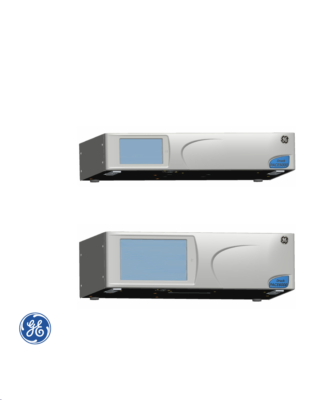
Pressure Automated Calibration Equipment
User manual - K0443 Revision A
PACE5000
PACE6000
© 2008 General Electric Company. All Rights Reserved. Specifications are subject to change
without notice. GE is a registered trademark of General Electric Company. Other company or
product names mentioned in this document may be trademarks or registered trademarks of their
respective companies, which are not affiliated with GE.
Page 2
PACE Pressure Controller User Manual
Introduction
This manual contains Installation and operating instructions for PACE Pneumatic Pressure
Controllers.
Safety
The manufacturer has designed this equipment to be safe when operated using the procedures
detailed in this manual. Do not use this equipment for any other purpose than that stated, the
protection provided by the equipment may be impaired.
This publication contains operating and safety instructions that must be followed to make sure of
safe operation and to maintain the equipment in a safe condition. The safety instructions are either
warnings or cautions issued to protect the user and the equipment from injury or damage.
Use qualified * technicians and good engineering practice for all procedures in this publication.
Pressure
Do not apply pressures greater than the maximum working pressure to the equipment.
Toxic Materials
There are no known toxic materials used in construction of this equipment.
Maintenance
The equipment must be maintained using the procedures in this publication. Further
manufacturer’s procedures should be carried out by authorized service agents or the
manufacturer’s service departments.
Technical Advice
For technical advice contact the manufacturer.
* A qualified technician must have the necessary technical knowledge, documentation,
special test equipment and tools to carry out the required work on this equipment.
General Specification
Display LCD: Colour display with touch screen
EMC EN61326
Electrical safety EN 61010-1, UL61010-1, CSA 22.2, No. 61010-1 and IEC 61010-1
PACE 5000: Input range: 100-240V (50/60Hz) 2A, Installation Catergory II, Fuse
Power Supply
Pressure safety Pressure equipment Directive - class: sound engineering practice (SEP)
T2AH250V
PACE 6000: Input range: 100-120/200-240V (50/60Hz) 5A, Installation Catergory II, Fuse T5AH250V
[EN] English i K0443 Revision A
Page 3
Environmental Conditions
Operating Environment Indoor use only
Operating temperature 10°C to 50°C (50° to 122°F)
Storage temperature -20°C to 70°C (-4° to 158°F)
Ingress protection IP20 (EN60529)
Operating humidity 5% to 95% RH (non-condensing)
Vibration MIL-PRF-28800 Type 2 class 5 Style E/F
Operating altitude Maximum 2000 metres (6560ft)
Pollution degree 2
Abbreviations
The following abbreviations are used in this manual; the abbreviations are the same in the singular and plural.
a Absolute min Minute or minimum
a.c Alternating current mm millimetre
ALT Altitude mV millivolts
ASCII American Standard Code for Information Interchange MWP Maximum working pressure
BSP British pipe thread No Number
CAS Calibrated airspeed NPT National Pipe Thread
CSK Countersunk PACE
d.c. Direct current Para. Paragraph
DPI Digital Pressure Instrument PDCR Pressure transducer
etc. And so on PED Pressure equipment directive
e.g. For example psi Pounds per square inch
Fig. Figure PTX Pressure transmitter
ft Foot ROC Rate of climb (vertical speed)
g Gauge RS232 Serial communications standard
GPIB General purpose interface bus Rt CAS Rate of Calibrated airspeed
Hg Mercury Rt MACH Rate of MACH
Hz Hertz Rx Receive data
IAS Indicated airspeed SCPI
IDOS Intelligent digital output sensor (GE product) SDS Sales data sheet
i.e. That is SELV
IEEE 488
in Inch UUT Unit under test
kg kilogram V Volts
kts knots +ve Positive
m Metre -ve Negative
mA milliampere °C Degrees Celsius
max Maximum °F Degrees Fahrenheit
mbar Millibar
Institute of Electrical and Electronic Engineers standard
488 (for programmable devices with a digital interface)
Tx Transmit data
Pressure automated calibration
equipment
Standard commands for
programmable instruments
Separated (or Safety) extra low
voltage
K0443 Revision A ii [EN] English
Page 4
PACE Pressure Controller User Manual
Related publications
K0447 PACE 5000/6000 User Guide and Safety Instructions
K0450 PACE Series Calibration Manual
K0476 Pressure Control Module User Guide and Safety Instructions
K0472 Remote Communications Manual
K0469 Heritage Communications Manual - Instrument Emulation
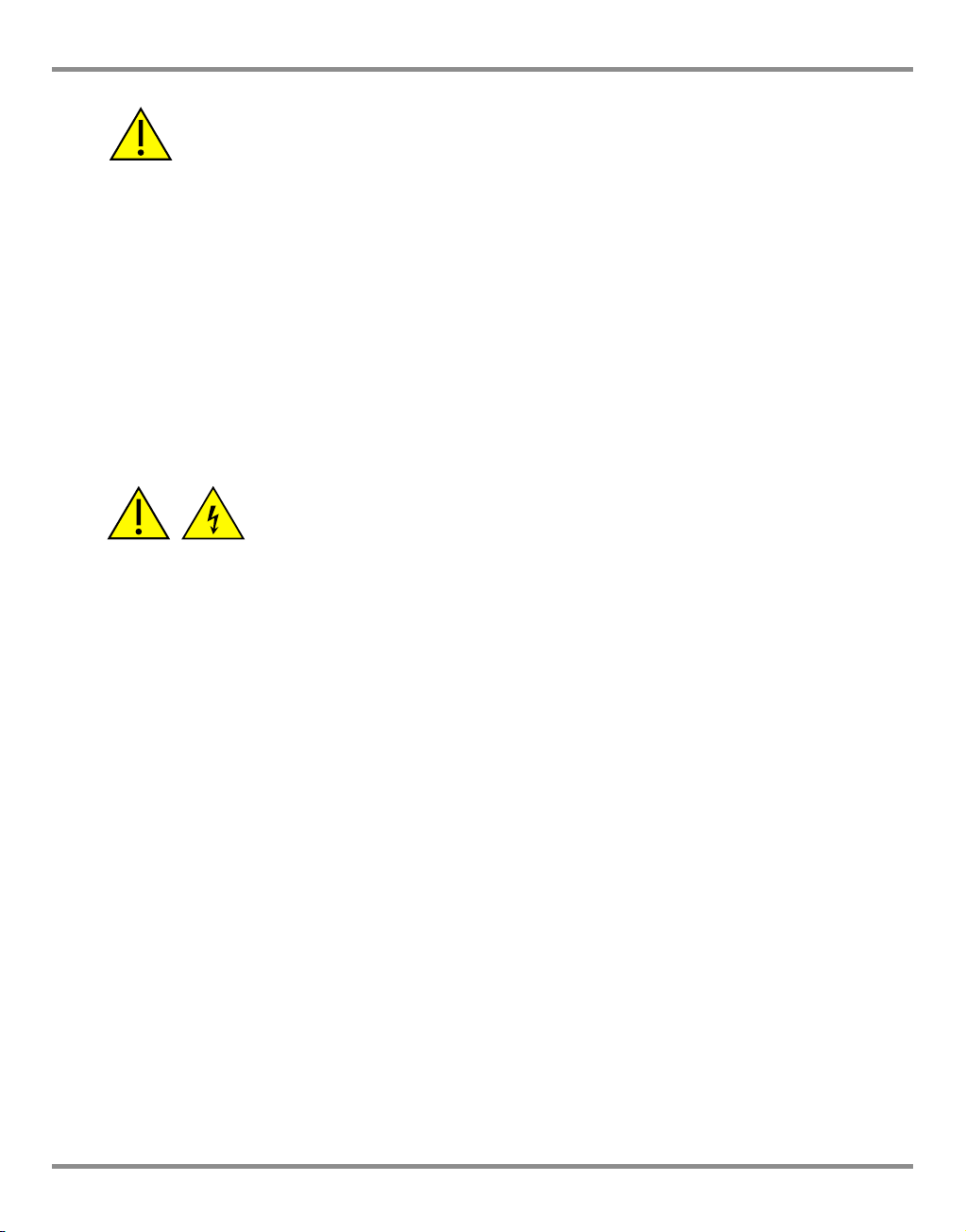
Symbols
This equipment meets the requirements of all relevant European safety directives.
The equipment carries the CE mark.
This symbol, on the equipment, indicates that the user should read the user manual.
This symbol, on the equipment, indicates a warning and that the user should refer to
the user manual.
Ce symbole, sur l’instrument, indique que l’utilisateur doit consulter le manuel d’utilisation. Ce symbole, dans le manuel, indique une situation dangereuse.
This symbol warns the user of the danger of electric shock.
Ce symbole alerte l’utilisateur sur le danger de choc électrique.
Do not dispose of this product as household waste. Use an approved organisation
that collects and/or recycles waste electrical and electronic equipment. For more
information, contact one of these:
- Our customer service department: www.gemeasurement.com
- Your local government office.
[EN] English iii K0443 Revision A
Page 5
WARNINGS
TURN OFF THE SOURCE PRESSURE(S) AND CAREFULLY VENT THE PRESSURE LINES BEFORE
DISCONNECTING OR CONNECTING THE PRESSURE LINES. PROCEED WITH CARE.
ONLY USE EQUIPMENT WITH THE CORRECT PRESSURE RATING.
BEFORE APPLYING PRESSURE, EXAMINE ALL FITTINGS AND EQUIPMENT FOR DAMAGE.
REPLACE ALL DAMAGED FITTINGS AND EQUIPMENT. DO NOT USE ANY DAMAGED
FITTINGS AND EQUIPMENT.
DO NOT EXCEED THE MAXIMUM WORKING PRESSURE OF THE INSTRUMENT.
THIS EQUIPMENT IS NOT RATED FOR OXYGEN USE.
THE GROUND LEAD OF THE INSTRUMENT MUST BE CONNECTED TO THE AC SUPPLY
PROTECTIVE SAFETY GROUND.
ISOLATE THE POWER SUPPLY BEFORE MAKING ANY ELECTRICAL CONNECTIONS TO THE
REAR PANEL.
K0443 Revision A iv [EN] English
Page 6
PACE Pressure Controller User Manual
Pressure units and conversion factors
Pressure units Factor (hPa) Pressure units Factor (hPa)
mbar 1.0
bar 1000.0
cmH
mH
O @ 20°C
2
O @ 20°C
2
0.978903642
97.8903642
2
Pa (N/m
)
hPa 1.0
0.01
kg/m
kg/cm
2
2
0.0980665
980.665
kPa 10.0 torr 1.333223684
MPa 10000.0 atm 1013.25
mmHg @ 0°C 1.333223874 psi 68.94757293
cmHg @ 0°C 13.33223874
mHg @ 0°C 1333.223874
inHg @ 0°C 33.86388640341
mmH
cmH
mH
mmH
O @ 4°C
2
O @ 4°C
2
O @ 4°C
2
O @ 20°C
2
0.0980665
0.980665
98.0665
0.097890364
inH
inH
inH20 @ 60°F
ftH2O @ 4°C
ftH2O @ 20°C
ftH20 @ 60°F
2
lb/ft
O @ 4°C
2
O @ 20°C
2
0.4788025898
2.4908891
2.486413
2.487641558
29.8906692
29.836983
29.8516987
Unit Conversion
Convert FROM pressure VALUE 1 in pressure UNITS 1 TO pressure VALUE 2 in pressure UNITS 2,
calculate as follows:
VALUE 2 = VALUE 1 x FACTOR 1
FACTOR 2
[EN] English v K0443 Revision A
Page 7

CONTENTS
Section Title Page
1 Description 1-1
1.1 Introduction 1-1
2 Installation 2-1
2.1 Packaging 2-1
2.2 Packaging for Storage and Transportation 2-1
2.3 Preparation for Use 2-1
2.4 Pneumatic connections 2-2
2.5 Rack-mount option 2-8
2.6 Electrical connections 2-9
3 OPERATION 3-1
3.1 Preparation 3-1
3.2 Power-up Sequence 3-2
3.3 Measure Mode 3-3
3.4 Control Mode 3-6
3.5 Operation and Example Procedures 3-10
3.6 Global Set-up Selections 3-14
3.7 Barometric Reference Option 3-15
3.8 Supervisor Set-up 3-16
3.9 Instrument Status 3-17
4 MAINTENANCE 4-1
4.1 Introduction 4-1
4.2 Visual inspection 4-1
K0443 Revision A vi [EN] English
Page 8

PACE Pressure Controller User Manual
4.3 Cleaning 4-1
4.4 Test 4-1
4.5 Calibration 4-2
4.6 Replacement parts 4-2
4.7 Fuse replacement 4-2
4.8 Filter replacement 4-4
4.9 Pressure module replacement 4-5
5 TESTING AND FAULT FINDING 5-1
5.1 Introduction 5-1
5.2 Standard Serviceability Test 5-1
5.3 Fault Finding 5-3
5.4 Approved Service Agents 5-3
6 REFERENCE AND SPECIFICATION 6-1
6.1 Installation notes 6-1
6.2 Operational Requirements 6-4
6.3 Icons 6-6
6.4 Measure Set-up 6-9
6.5 Control Set-up 6-10
6.6 Global Set-up 6-11
6.7 Supervisor Set-up 6-12
6.8 Options 6-24
6.9 Calibration 6-41
6.10 Communications - Instrument Emulation 6-41
6.11 Specification 6-41
6.12 Return Goods/Material Procedure 6-41
6.13 Packaging Procedure 6-42
[EN] English vii K0443 Revision A
Page 9

6.14 Vacuum System Parts 6-43
K0443 Revision A viii [EN] English
Page 10
PACE Pressure Controller User Manual
1Description
1.1 Introduction
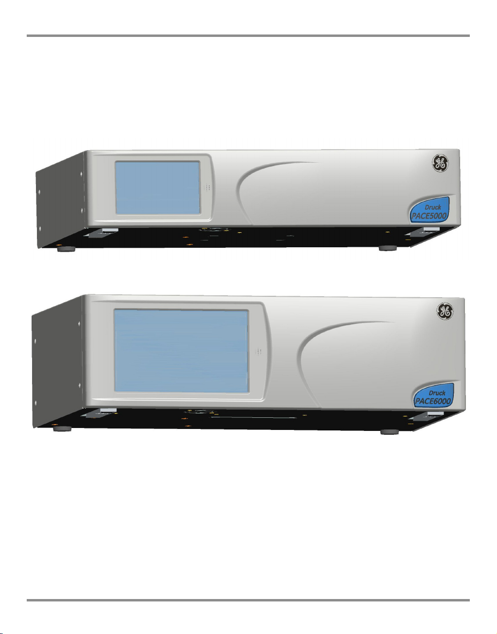
The PACE5000 single-channel and PACE6000 single/dual-channel, Pressure Automated
Calibration Equipment measures and controls pneumatic pressures and displays, on a
touch-screen, the pressure measurement and controller status. The touch-screen enables
selections and settings in both measure and control modes. The instrument can be operated
remotely through communication interfaces.
Figure 1-1 PACE5000 General view
Figure 1-2 PACE6000 General view
The rear of the instrument houses all the electrical and pneumatic output and input
connections. The electrical connections provide an a.c. power supply, serial and parallel
communication interfaces, d.c. output and logic input and output. The system pneumatic
controller module contains a positive and negative pressure supply port, an output port,
vent port and reference port.
The instrument can be mounted in a standard 19 inch rack system (rack-mount option).
[EN] English 1 - 1 K0443 Revision A
Page 11
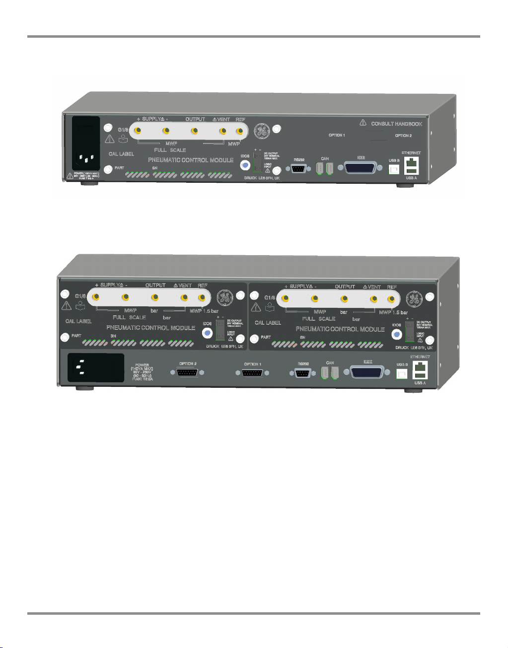
1 Description
Figure 1-3 PACE5000 Rear view
Figure 1-4 PACE6000 Rear view
Options available are detailed in the product datasheet.
Information and notes on applications (Ref: Reference and Specification, Section 6) or
www.gemeasurement.com
K0443 Revision A 1 - 2 [EN] English
Page 12
PACE Pressure Controller User Manual
2 Installation
2.1 Packaging
Check the contents of the PACE5000/6000 packaging with the list that follows:
Packaging List
i) PACE5000 or PACE6000 Pressure Controller.
ii) Cable, power supply.
iii) User guide and CD (UD-0001) containing the full documentation suite.
iv) Pneumatic Control Module blanking plate (keep this plate for future use).
CAUTIONS
After removing a control module, use a blanking plate to keep the flow of cooling air.
After unpacking an instrument that has been in cold conditions allow time to stabilise
and any condensation to evaporate.
2.2 Packaging for Storage or Transportation
To store or return the instrument for calibration/repair do the procedures that follow:
1. Pack the instrument (Ref: Reference and Specification, Section 6.8).
2. Return the instrument for calibration/repair complete the return goods procedure (Ref:
Reference and Specification, Section 6.8).
Note: The procedure above applies to the pressure control module as a separate item.
2.3 Preparation for Use
The instrument can be used as a:
• Free-standing instrument positioned on a horizontal surface.
• Rack-mounted in a standard 19 inch rack using the rack-mount option kit (Ref: Section
2.5, Rack-mount option).
For free-standing instruments, the feet on the front of the base can be used elevate the
instrument to a better viewing angle.
Note: Do not obstruct the air cooling outlet on the underside of the instrument and allow a free
flow of air around the instrument, especially at high ambient temperatures.
[EN] English 2 - 1 K0443 Revision A
Page 13
2 Installation
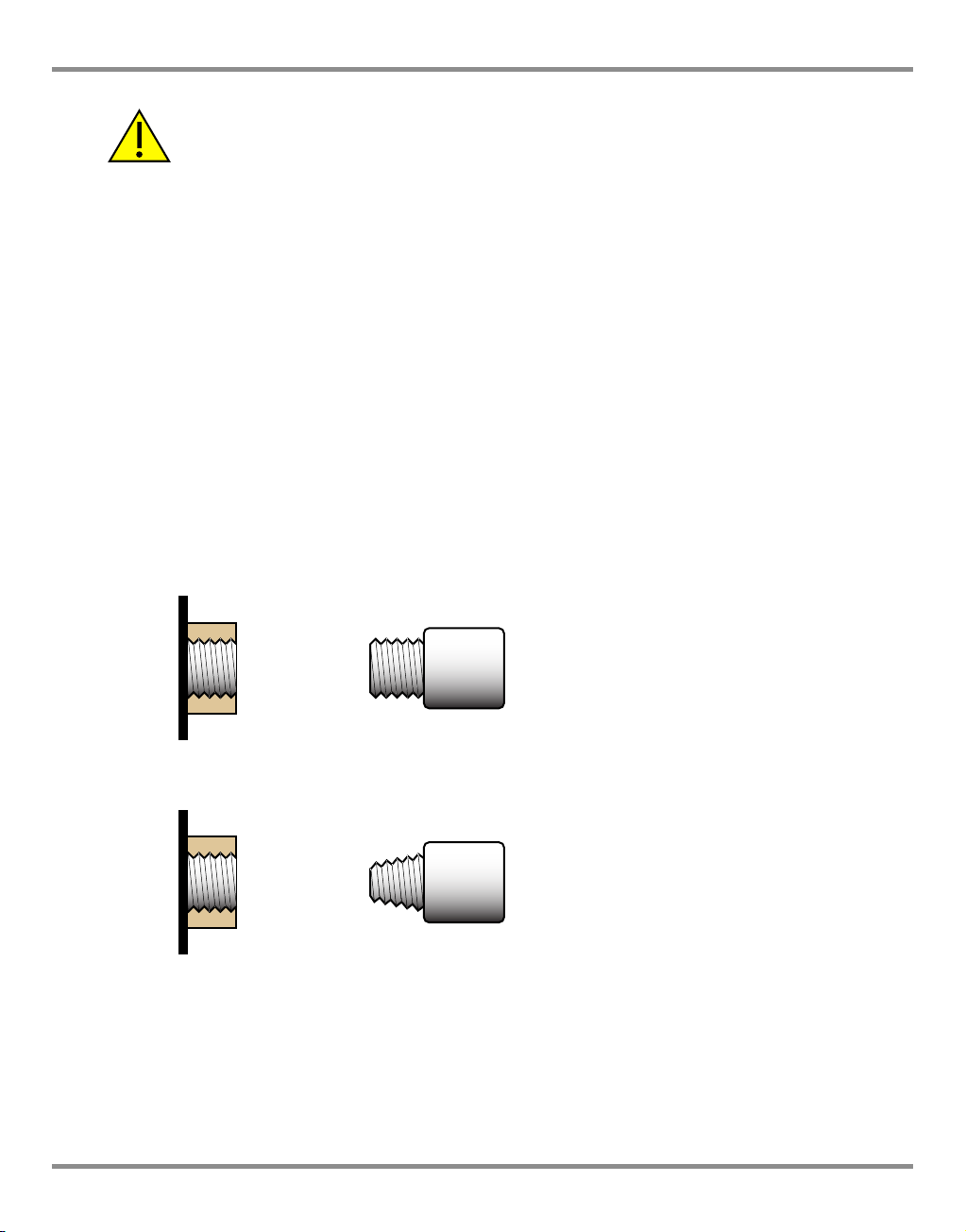
Parallel threads must be used.
Female thread type is parallel thread to
ISO228/1 (DIN ISO228/1, JIS B0202)
G1/8
Tapered threads NOT allowed.
PACE pressure port
PACE rear
panel
9
8
PACE rear
panel
PACE pressure port
2.4 Pneumatic connections
WARNINGS
TURN OFF THE SOURCE PRESSURE(S) AND CAREFULLY VENT THE PRESSURE LINES BEFORE
DISCONNECTING OR CONNECTING THE PRESSURE LINES. PROCEED WITH CARE.
ONLY USE EQUIPMENT WITH THE CORRECT PRESSURE RATING.
BEFORE APPLYING PRESSURE, EXAMINE ALL FITTINGS AND EQUIPMENT FOR DAMAGE.
REPLACE ALL DAMAGED FITTINGS AND EQUIPMENT. DO NOT USE ANY DAMAGED
FITTINGS AND EQUIPMENT.
DO NOT EXCEED THE MAXIMUM WORKING PRESSURE OF THE INSTRUMENT.
THIS EQUIPMENT IS NOT RATED FOR OXYGEN USE.
PARALLEL THREADS MUST BE USED. FEMALE THREAD TYPE IS PARALLEL THREAD TO
ISO228/1 (DIN ISO228/1, JIS B0202) G1/8.
TAPERED THREADS NOT ALLOWED.
K0443 Revision A 2 - 2 [EN] English
Page 14
PACE Pressure Controller User Manual
2
1
1 Connector
2 Bonded seal
Connection Port
Input
Output
Refer to the data sheet for a complete range of adaptors.
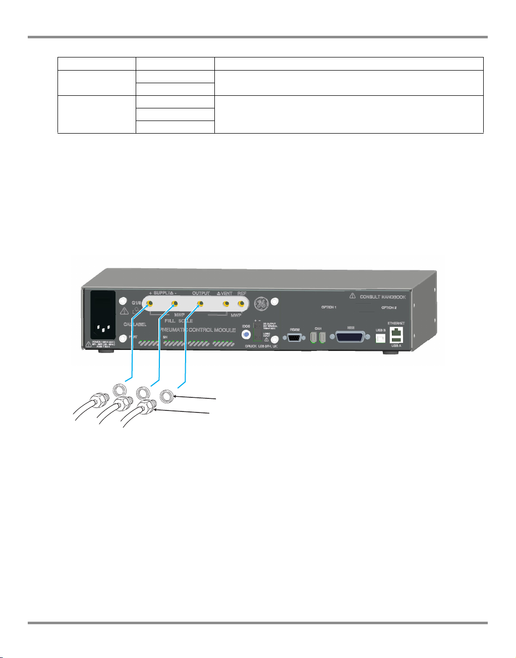
Pressure supply (Ref: Figure 2-1, Pneumatic connections)
1. The pressure supply must be clean, dry gas, nitrogen or air and at the correct pressure,
(Ref: Section 6, Reference and Specification).
2. Make sure the user systems can be isolated and vented.
3. Connect pressure and vacuum supplies to the SUPPLY + and SUPPLY - connection
ports.
4. Connect the Unit Under Test (UUT) to the required output connection port.
supply +
supply Output
Reference
ISO228/1 G 1/8 parallel threads (DIN ISO228/1, JIS B0202)
ISO228/1 G 1/8 parallel threads (DIN ISO228/1, JIS B0202)Vent
Figure 2-1, Pneumatic Connections
Note: For systems requiring NPT connections, please order optional NPT adaptors.
[EN] English 2 - 3 K0443 Revision A
Page 15
2 Installation
Installation
The safety of any system incorporating the equipment is the responsibility of the assembler
of the system.
The instrument requires a positive pressure supply, instruments operating in an absolute
range or negative pressure range require a vacuum supply.
A vacuum supply should be used for a fast response for instruments operating near
atmospheric pressure.
For dual channel operation two independent pressure and vacuum supplies can be used.
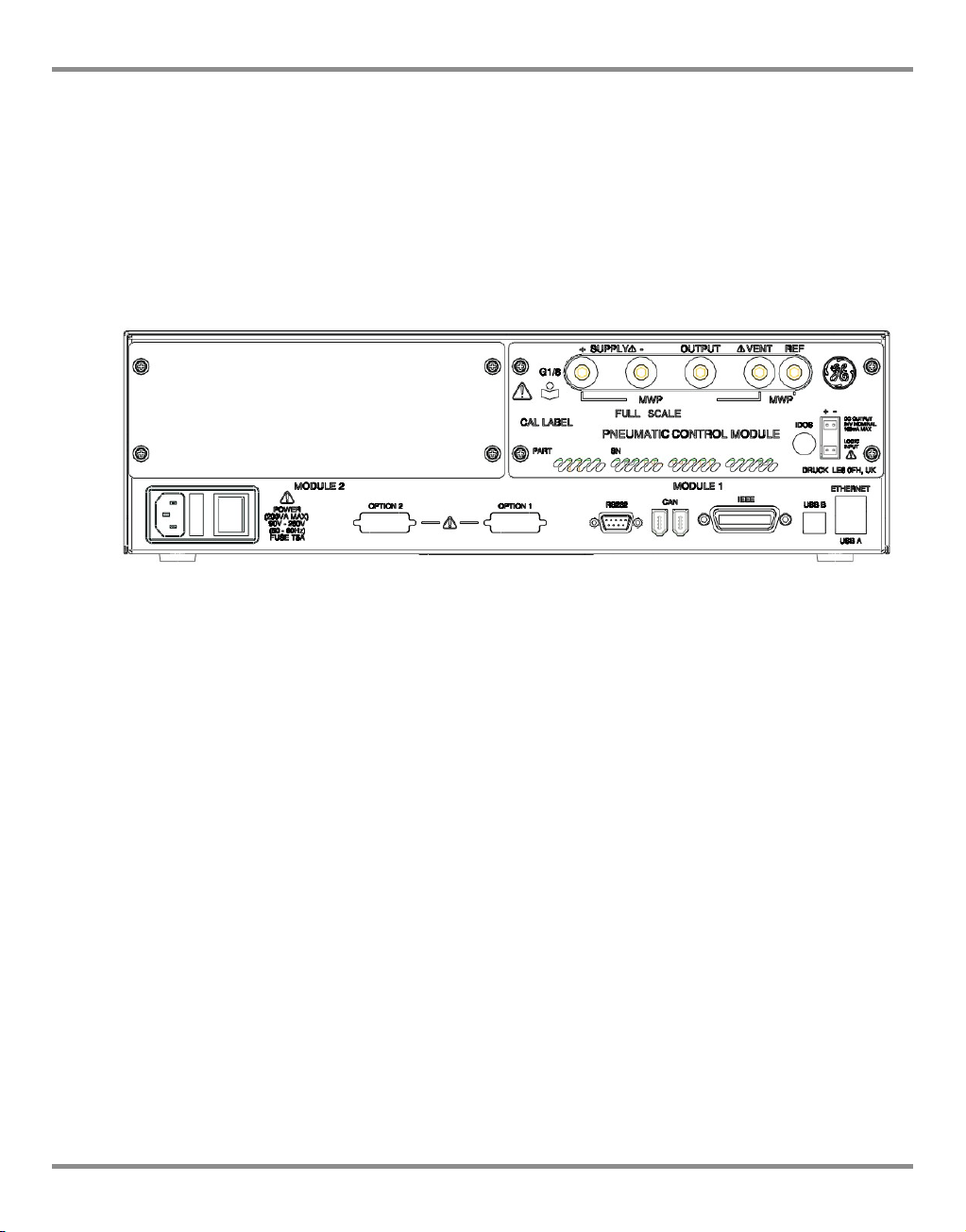
Figure 2-2, Pressure module rear view
Note: When using two pressure modules (Ref: Section 4.9, Pressure module replacement)
make sure that:
• The module with the highest pressure rating is fitted to the right hand side
Module 1 position as viewed from the rear of the product refer to (Ref: Fig 2-2)
• If two modules have the same pressure rating, make sure that the module with
the higher serial number is fitted to the right hand side Module 1 position as
viewed from the rear of the product.
Note: All pneumatic connections must comply with the Pressure Equipment Directive (PED)
or other regional pressure standards.
Note: When connecting the output ports of two pressure modules together make sure both
are either:
• below 70 bar
OR
• between 100 to 210 bar.
To prevent over-pressurisation of pneumatic parts and maintain compliance with the PED do
not mix categories.
K0443 Revision A 2 - 4 [EN] English
Page 16
PACE Pressure Controller User Manual
OUTPUT
1
2
3
4
5
6
7
+
5
9
a
-
SUPPLY
VENT REF
8
14
14
Supply equipment
Pneumatic supplies should have isolation valves and, where necessary, conditioning
equipment.
The positive pressure supply should be regulated to between 110% of the full-scale pressure
range and MWP stated on the control module.
To protect the instrument from over-pressure a suitable protection device (such as a relief
valve or bursting disc) must be fitted to prevent over pressurization.
On instruments without a negative supply, the positive pressure discharges from the system
to atmosphere through the negative supply port. Pipe the negative port to a safe discharge
area or fit a diffuser to the negative port.
During system pressure vent operations, the pressure discharges from the system to
atmosphere through the negative and vent ports. Pipe both ports to a safe discharge area or
fit a diffuser to the negative port.
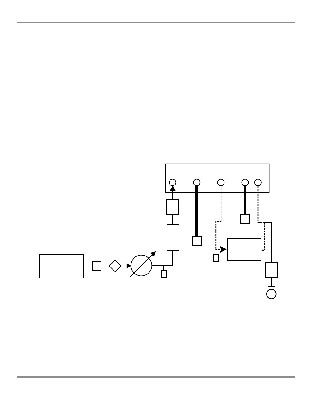
Pneumatic Connection Examples (Ref: Figures 2-3, 2-4 and 2-5)
The examples that follow show a single channel connection detail, using supply equipment
described above.
Figure 2-3, Pneumatic Connections without vacuum supply
1) Pressure source 2) Conditioner 3) Filter
4) Regulate to between 110% full-scale and MWP 5) Diffuser*
6) Unit under test 7) Optional reservoir † 8) Protection device
9) Optional differential connection 14) Manual external vent valves
a) Atmosphere
[EN] English 2 - 5 K0443 Revision A
Page 17
2 Installation
1
2
3
4
5
6
7
8
9
13
7
10
12
11
a
OUTPUT
+
-
SUPPLY
VENT REF
14
14
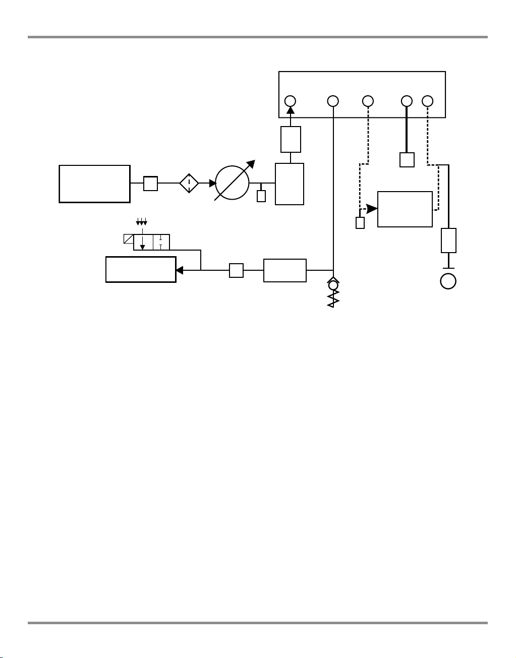
Note: (Ref: Section 6, Reference and Specification) for details of other system components.
Figure 2-4, Pneumatic Connections with vacuum supply
1) Pressure source 2) Conditioner 3) Filter
4) Regulate to between 110% full-scale and MWP 5) Diffuser*
6) Unit under test 7) Optional reservoir † 8) Protection device
9) Optional differential connection 10) Oil mist trap
11) Vacuum source 12) Normally open electrical release valve 13) Check valve **
14) Manual external vent valves a) Atmosphere
Note: The PACE option IO-VAC-SYS Vacuum System Check Valve Kit should be used in the
vacuum line mounted near the PACE CM -ve port to exhaust most HP gas directly to
atmosphere. The vacuum buffer volume needs to be rated at least to the highest
system pressure.
Note: (Ref: Section 6, Reference and Specification) for details of other system components
K0443 Revision A 2 - 6 [EN] English
Page 18
PACE Pressure Controller User Manual
1
2
3
4
7
8
5
6
9
13
7
10
12
11
+
-
a
14
14
SUPPLY
OUTPUT
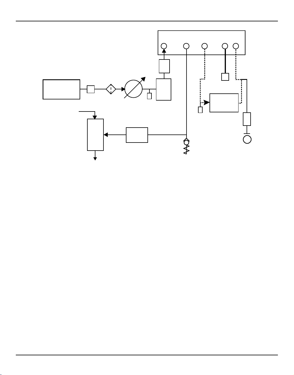
Figure 2-5, Pneumatic Connections with negative gauge pressure generator
1) Pressure source 2) Conditioner 3) Filter
4) Regulate to between 110% full-scale and MWP 5) Diffuser *
6) Unit under test 7) Optional reservoir †
9) Optional differential connection
10) Vacuum generator ‡ 11) Source pressure (regulated compressed air supply)
12) Exhaust to atmosphere 13) Check valve ** 14) Manual external vent valves
8) Protection device
a) Atmosphere
VENT REF
Notes: (Ref: Section 6 Reference and Specification) for details of other system components.
* High pressure gas exhaust - depending on pressure range.
** Optional vacuum system kit, allows the -ve port gas to be directly discharged to
atmosphere, by-passing the vacuum pump.
† Optimum controller transient response and minimum time to set-point may be
degraded if either the pneumatic supply or vacuum system has restricted flow.
Installing a reservoir volume, which has larger capacity than the load volume, located
in close proximity to the controller supply ports can improve the controller response.
‡ Optional negative gauge pressure generator kit.
To protect the control module, for ranges of 70 bar and above from over-pressure a
suitable protection device (such as a relief valve or bursting disc) must be fitted to limit
the applied supply pressure to below the MWP.
Optional differential connection kit.
[EN] English 2 - 7 K0443 Revision A
Page 19
2 Installation
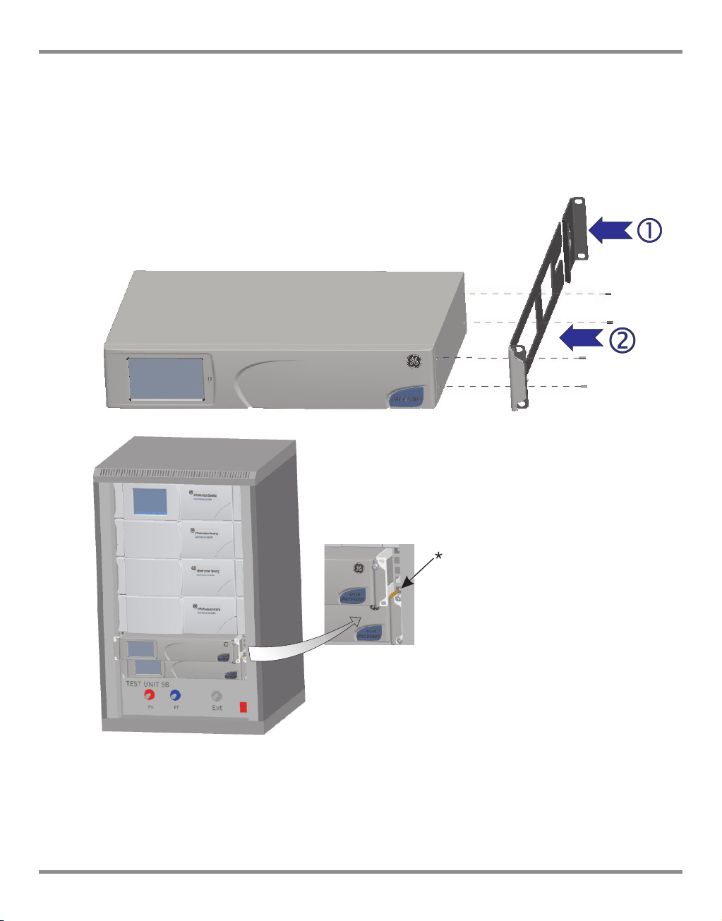
2.5 Rack-mount option (Ref: Figure 2-6)
General
There must be enough space at the rear of the instrument for all the cables and pipes. The
length of the cables and pipes must allow for the removal and fitment of the instrument. The
cooling air of the instrument must not be obstructed. Allow a free flow of air through the
equipment rack and around the instrument, especially at high ambient temperatures.
Figure 2-6 Rack-mounting
K0443 Revision A 2 - 8 [EN] English
Page 20
PACE Pressure Controller User Manual
Procedure
1. Locate bracket in rack assembly
2. Remove the four M3x10mm countersunk screws from each of the instrument side
panels.
3. Locate the two brackets
4. Secure with the four countersunk screws.
5. Support the instrument and connect the cables and pipes.
6. Refer to the electrical connections below before fitting the instrument into the rack.
7. Temporarily locate the two spigots * to each side of the equipment rack.
8. Locate and slide the instrument into the rack.
9. Locate the instrument on the spigots*.
10. Secure the instrument in the equipment rack with two of the screws and washers
(supplied).
11. Remove the two spigots* and replace with the remaining two screws and washers
(supplied).
2.6 Electrical connections
WARNINGS
THE GROUND LEAD OF THE INSTRUMENT MUST BE CONNECTED TO THE AC SUPPLY
PROTECTIVE SAFETY GROUND.
on each side of the instrument.
.
ISOLATE THE POWER SUPPLY BEFORE MAKING ANY ELECTRICAL CONNECTIONS TO THE
REAR PANEL.
Connecting (Ref: Figure 2.7 Electrical connections)
1. Install an accessible power isolator to use as the disconnecting device in the power
supply circuit.
2. For the power input power supply range, Installation Category and VA (Ref:
Introduction, General specification table).
Note: The power must be supplied by a fused or overload-protected power supply.
3. Connect the power supply to the instrument.
4. Switch the power supply on.
5. Check that the front panel display shows the power-up sequence (Ref: section 3.2,
Power-up sequence).
[EN] English 2 - 9 K0443 Revision A
Page 21
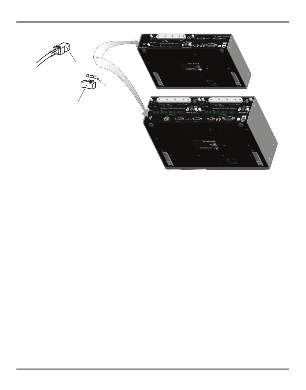
2 Installation
3
2
1
1 IEC power connector
2 Fuse carrier
3 Fuse
Figure 2-7 Electrical Connections
Pressure Control Module Input and Output Connectors
24V DC Output @ 100mA maximum
4-way connector: pin “+” = +24 Vdc
pin “-” = 0 Vdc
An integral self-resetting fuse protects this output.
Logic (switch) Input
4-way connector: Input
Output
This facility can be used to trigger the instrument from a pressure switch contact during the
Pressure Switch Task (Ref Section 3.4, Control Mode).
Connections are not polarised and can be connected either way. Integral opto-isolators
protect this input circuit.
This facility can be energised by external SELV compliant equipment.
K0443 Revision A 2 - 10 [EN] English
Page 22
PACE Pressure Controller User Manual
1
3
4
5
6
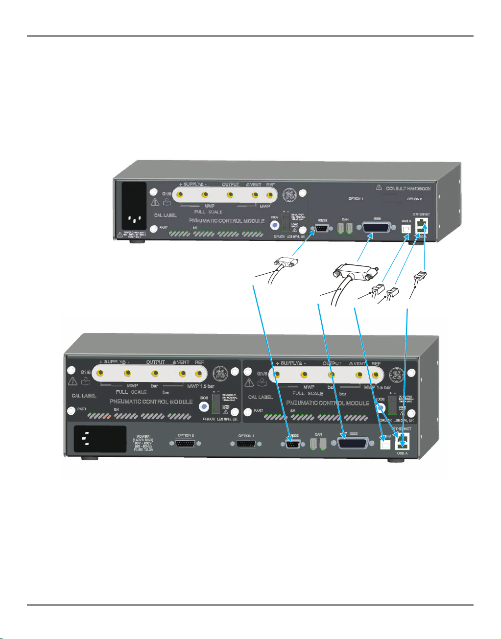
Communication Connections (Ref: Fig 2-8 Communication Connectors)
Connect the applicable connectors into the rear panel communications ports and, if
appropriate, secure with the captive screws.
Note: Refer to the data sheet for a list of optional communication ports.
Refer to the data sheet for a list of standard shipped communication ports.
Set the required parameters in Supervisor Setup/communications menu, (Ref: Section 3.8,
Supervisor set-up).
Figure 2-8, Communication Connectors
1 RS232 3 IEEE488 4 USB B
5 USB A 6 Ethernet
[EN] English 2 - 11 K0443 Revision A
Page 23
2 Installation
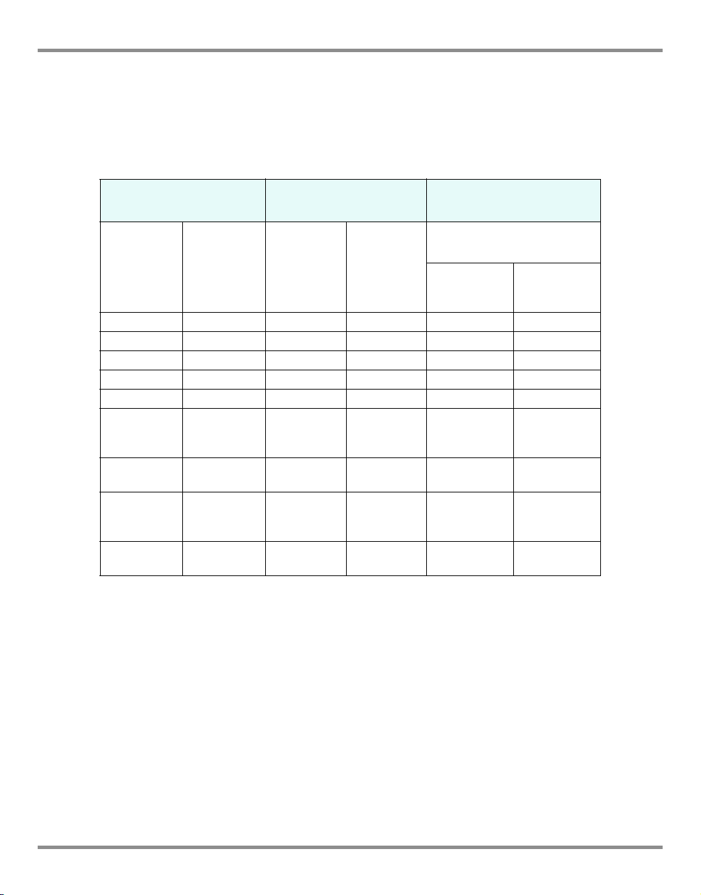
RS232 Interface
When using the RS232 interface, a cable must be connected directly from the instrument to
a suitable port on the computer in a ‘point to point’ link. The pin connections for the 9-pin Dtype, RS232 connector and the relationship between the instrument and the RS232 control
signals, together with device interconnection interface is shown in Table 2-1. The instrument
is configured as Data Circuit Terminating Equipment (DCE).
Instrument Control Line Computer/Printer
Instrument
Function
RxD (I/P) 3 TxD 3 2
TxD (O/P) 2 RxD 2 3
GND 5 GND 5 7
CTS (I/P) 7 RTS 7 4
RTS (O/P) 8 CTS 8 5
Pulled
high
internally
Not
connected
Pulled
high
internally
Equipment
chassis
Connector
9-way
D-type
Pin No.
1
4 DTR 4 20
6
Connector
shell
Signal
Direction
Cable Screen - 1
RS232
Terminology
RLSD
(DCD)
DSR
DCE Ready
9-way
D-type
Pin No.
18
66
Table 2-1, RS232 Connections
Handshaking connections
Connector Type
25-way
D-type
Pin No.
Software handshaking use: TXD, RXD and GND.
Hardware handshaking use: TXD, RXD, GND, CTS, RTS and DTR.
K0443 Revision A 2 - 12 [EN] English
Page 24
PACE Pressure Controller User Manual
2
3
IEEE 488 Interface
The interface complies with IEEE 488 standard.
The IEEE 488 parallel interface connects a computer/controller to one or more PACE
instruments and other instruments.
Up to 30 instruments can be connected through a high-speed data bus to the computer/
controller.
Note: The length of each IEEE 488 cable must be less than 3 metres to comply with the EMC
requirements (Ref: Section 6,
Single Unit Installation (Ref: Figure 2-9)
1. Connect an IEEE 488 connector/cable assembly to the rear panel of the instrument.
2. Connect the other end of the connector/cable assembly to the IEEE 488 connector on
the controller/computer.
3. Change the IEEE 488 communication parameters (Ref: Section 6.7, Supervisor set-up).
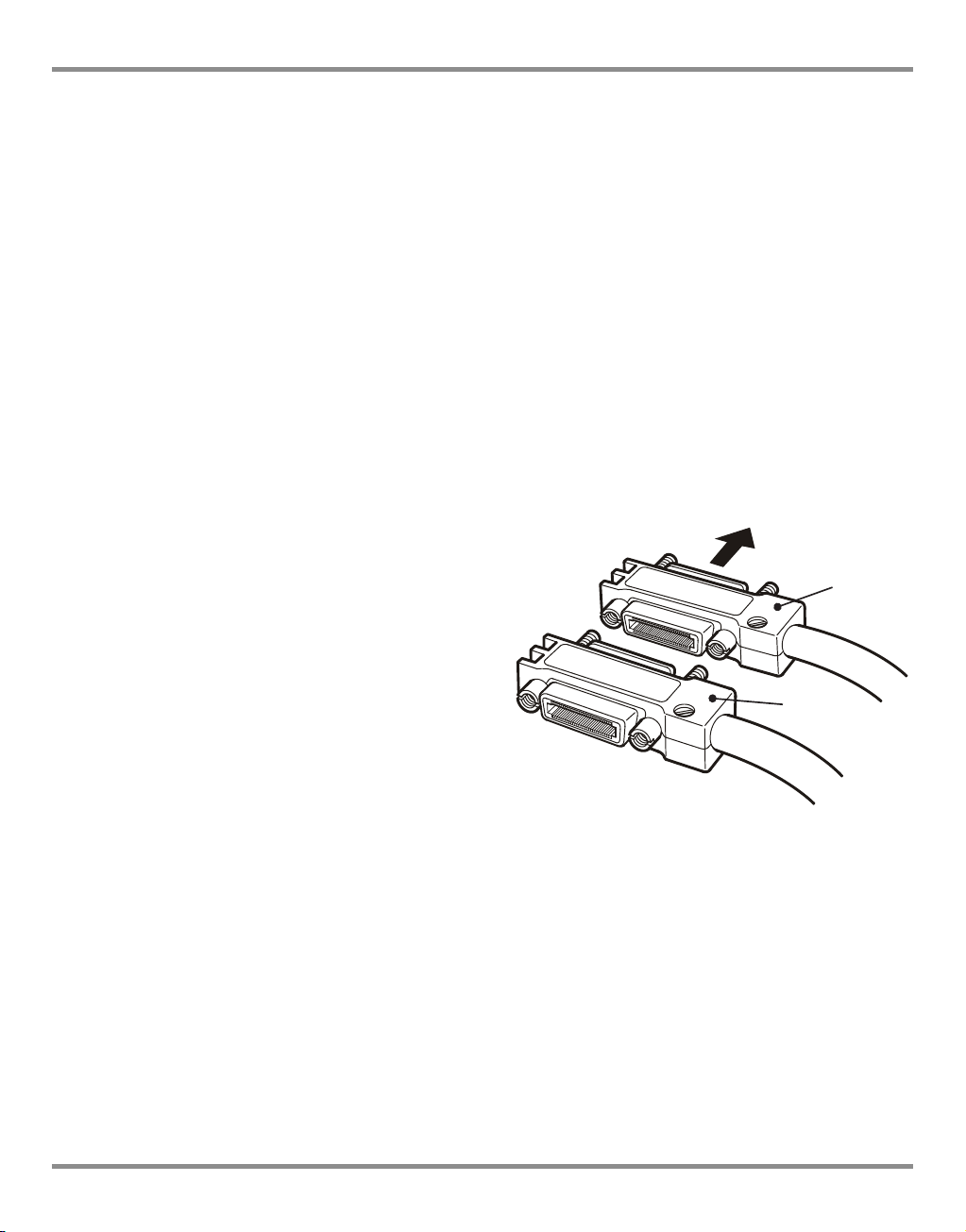
Multiple Unit Installation (Ref: Figure 2-9)
Reference and Specification).
To install multiple units use stacking plugs to
1
link the first instrument and second
instrument as follows.
1 Connector to rear panel of first
instrument (Ref Illustration).
2 Connector from controller/computer
(Ref Illustration).
3 Connector to rear panel of second
instrument (Ref Illustration).
4. Connect the IEEE 488 connector on
the controller/computer and the other
connector into the next instrument.
5. Repeat this procedure for all the instruments in the system.
6. Use the Supervisor set-up (communications) menu on each instrument to set-up the
required communication parameters (Ref: Section 3.8, Supervisor set-up).
[EN] English 2 - 13 K0443 Revision A
Page 25
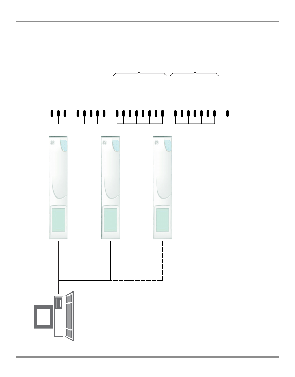
2 Installation
IEEE 488
ADDRESS 1
ADDRESS 2
ADDRESS N
(30 maximum)
678
DAV (DATA VALID)
NRFD (NOT READY FOR DATA)
NDAC (NO DATA ACCEPTED)
59101117
EOI (END OF IDENTIFY)
IFC (INTERFACE CLEAR)
SRQ (SERVICE REQUEST)
ATN (ATTENTION)
REN (REMOTE ENABLE)
123413
DIO1
DIO2
DIO3
DIO4
DIO5
141516
DIO6
DIO7
DIO8
1819202122
GND (6)
GND (7)
GND (8)
GND (9)
GND (10)
23
24
GND (11)
GND
12 CHASSIS/FRAMECHASSIS/FRAME
DATA /
STATUS
BAR
0V (GND)
Figure 2-9 - IEEE 488 Connection
K0443 Revision A 2 - 14 [EN] English
Page 26

PACE Pressure Controller User Manual
3Operation
This section contains quick reference charts detailing all the available functions and the setup menu.
3.1 Preparation
Make sure the electrical cables and pneumatic pipes comply with the installation
requirements (Ref: Section 2, Installation).
Before use do the following:
1. If necessary, do the maintenance task (Ref: Section 4, Maintenance).
2. For bench-top, single instrument operation do the following:
a. Connect the instrument to the electrical supply.
b. Inspect the pneumatic hoses for damage, ingress of dirt and moisture.
3. Before use, the instrument should be tested.
4. Review and become familiar with the procedure before starting a process on a
component or system.
Note: The touch-screen can be permanently damaged by sharp objects.
[EN] English 3 - 1 K0443 Revision A
Page 27
3 Operation
1
2
3
4
56
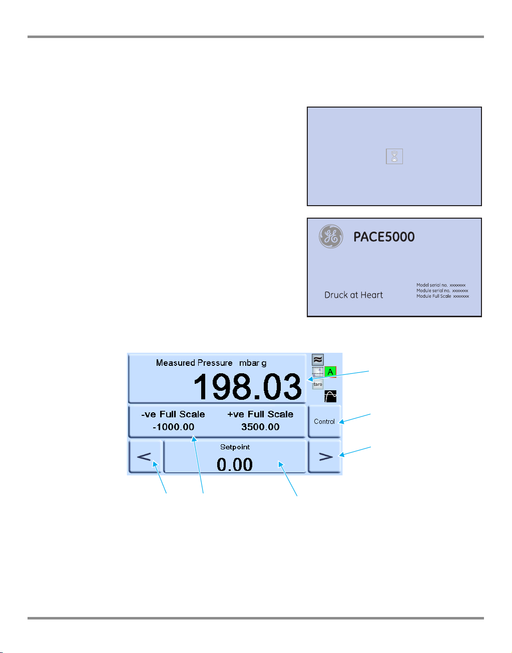
3.2 Power-up sequence
The following sequences of operation shows the instrument display.
Note: The following sequence is an example, the values and selections displayed depend on
the range(s) and options enabled in the instrument (Ref: Touch screen areas).
1. Set the power supply to ON:
2. The display shows the power-up sequence.
3. The instrument carries out a self-test.
If the test finds a fault, the display shows an
error (Ref: Fault Finding and Testing, Section
5).
4. If the self-test is successful the system
enables the touch screen and changes to
measure mode.
5. The touch screen shows the measured
pressure in the parameters selected in set-up.
6. The instrument is now ready for use.
Note: The PACE 6000 shows a single display
(default) this is the left hand pressure control
module. Change to dual display in Global Setup/Display.
Touch screen areas
Measure set-up
1
Status (touch to enter control set-up
5
Control/Measure
2
Nudge down
6
3
Nudge up
Set-point entry
4
K0443 Revision A 3 - 2 [EN] English
Page 28
PACE Pressure Controller User Manual
PACE5000
PACE6000
2
3
4
56
7
1
2
3
4
56
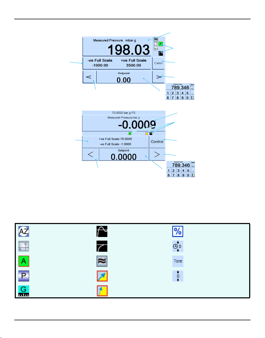
3.3 Measure mode
7
1
Pressure measurement of current selected sensor in current selected pressure measurement units
1
Current enabled functions
2
Nudge up, changed in control set-up
4
Nudge down, changed in control set-up
6
Control/measure selection
3
Current set-point value, change with numeric keys
5
Status area, changed in global set-up
7
Display Icons
Auto zero Control mode with overshoot Percentage
Reference level difference
(gas head correction)
Control mode with no
overshoot
Timed zero
Control mode active Filter pressure reading Tare enabled
Control mode passive Linear rate Zero
Control mode gauge Maximum rate
[EN] English 3 - 3 K0443 Revision A
Page 29
3 Operation
current pressure reading to zero,
offset stored for current range.
allows selection of available pressure
ranges. Ê
PACE5000
PACE6000
-
-
select from list of available
pressure measurement
units.
-
Absolute range selection available when
barometric option installed.
Auto-range only available with two-channel
instruments.
Ê
%
Filter pressure reading
Tare
Pressure zero
Range
Process
Task
Units
Global set-up
Set-up zero
Status
Measure set-up
More
Timed
Auto
Tare
Next page of menu options. Loops
from last page to first page.
Stores settings and exits
set-up.
see 3.6:-
next page:-
Exit set-up.
K0443 Revision A 3 - 4 [EN] English
Page 30

PACE Pressure Controller User Manual
AUTO-RANGE (only available with two-channel instruments)
Note: Not all Auto-Range and task functions are available using the remote
communications, this allows more flexibility to the remote programmer.
Controller Off – Increasing Set-point
With both controllers in Measure mode, if a set-point within the range of the lower ranged
controller is entered and Control is then selected the lower ranged controller controls to the
entered set-point.
With both controllers in Measure mode, if a set-point above the range of the lower ranged
controller is entered and Control is then selected, then the range is changed to the higher
ranged controller and this then controls to the entered set-point.
Controller Off – Decreasing Set-point
With both controllers in Measure mode, if a set-point within the range of the higher ranged
controller is entered and Control is then selected the higher ranged controller controls to the
entered set-point.
With both controllers in Measure mode, if a set-point above the range of the lower ranged
controller is entered and Control is then selected, then the higher ranged controller will
control to this set-point. When the controller is in limits then the range is changed to the
lower ranged controller and this then controls to the entered set-point .
Controller On – Increasing Set-point
With the lower ranged controller in Control mode, if a set-point within the range of the lower
ranged controller is entered then the lower ranged controller controls to the entered set-point.
If the set-point is increased to above the lower range but still within the higher range then the
lower range controller switches off and that the higher range controller switches on and controls
to the entered set-point.
Controller On – Decreasing Set-point
With the higher ranged controller in Control mode, if a set-point within the range of the
higher ranged controller is entered then the higher ranged controller controls to the entered
set-point.
If the set-point is decreased to within the lower range then the higher range controller will
control to this set-point. When the controller is in limits then the range is changed to the
lower ranged controller and this then controls to the entered set-point .
[EN] English 3 - 5 K0443 Revision A
Page 31

3 Operation
SUPPLY
OUTLET VENT REF
+-
Module 2
SUPPLY
OUTLET VENT REF
+-
Module 1
Pressure
output
Pressure
source
Pressure
regulator
Pressure
regulator
Rear view of
PACE6000
instrument
Control
Measure
1
2
3
4
5
6
7
3.4 Control Mode
In measure mode, press and the instrument changes to control mode.
Press and the instrument stops controlling pressure and changes to measure mode:
Key to display:
1 Current measured pressure value (in limits green, out of limits blue).
2 In active control mode.
Pressure reading filter ON.
Head (pressure) value applied.
Control mode with overshoot.
K0443 Revision A 3 - 6 [EN] English
Page 32

PACE Pressure Controller User Manual
Control
Tare enabled.
3 Press to switch between controlled pressure and measured pressure.
4 Nudge up.
5 Set-point, press and the display changes to numeric keys.
6 Nudge down.
7 Status area shows effort meter set in global set-up, press to enter control set-up.
Notes:
Active mode - control active, except in measure mode.
Passive mode - when the controller achieves inlimits condition, measure mode is
automatically selected.
Gauge mode - when the controller achieves zero gauge inlimits condition, measure mode is
automatically selected and the zero valve opens.
Controlling to a new set-point
1. To change the set-point value, touch the set-point area of the screen and the display
shows the numeric keys.
2. Set the new set-point value.
3. If necessary, use the key to remove the last digit in the set-point value display.
4. To save the new set-point, touch the set-point area of the screen. This returns the
display to the measured pressure screen and showing the new set-point.
5. Touch the escape to leave the numeric setting unchanged.
6. To control pressure to the new set-point value press the key.
7. The display shows the pressure value changing as the instrument controls to the new
set-point, at the set rate of change.
Note: When changing from measured to controlled mode the displayed pressure digits
change from black (measured pressure) to blue (controlled pressure out of limits) to
green (controlled pressure in-limits).
8. If enabled, the effort meter shows the effort the controller exerts to achieve the set-
[EN] English 3 - 7 K0443 Revision A
Page 33

3 Operation
Control
Measure
point.
9. The status area can be changed to various displays showing pressure and controller
performance.
Effort meter
Note: In normal controlled pressure conditions the effort meter stays within the band (green).
If the status indicator moves outside the band there may be a leak into or out of the
system.
Controlling to ambient/zero pressure
1. Use the numeric key display and set the new set-point value to ambient or zero gauge pressure.
2. When the display shows the new set-point value, press the key.
3. The display shows the pressure value changing as the instrument controls to the new set-point, at the set rate of change.
4. When the display shows ambient or zero pressure, press the key to switch off the controller and return to measure mode.
K0443 Revision A 3 - 8 [EN] English
Page 34

PACE Pressure Controller User Manual
Vent
Nudge resolution
Set-point limits
Slew rate
Control mode
Global set-up
Control set-up
Status
Vent set-up
-
Replaced by Go to Ground when in
aeronautical option.
Exit set-up.
Upper
Lower
Enable/disable
Yes/No Ê
-
Sets set-point
nudge resoultion.
1
st
to 7th digit.
-
Linear - Enter units/second
Maximum rate
Toggle between: fast/no overshoot
Active - Continuous control to set-point
Passive - Controls outside user defined band
Gauge - Controls from zero gauge to set-point
see 3.6:-
see 3.9:-
Ê
[EN] English 3 - 9 K0443 Revision A
Page 35

3 Operation
Selecting a task exits the menu and
changes the display to the task
selected.
Ê
Exit set-up.
Option refer to 6.8.
Ê
Enable
Set-up
Basic
Leak test
Switch test
Test program
Divider
Preset
Task
Ê
Start program
Set-up
Step
Stop
Ê
Enable
Set-up
Select program
Enable
Set-up - select a preset and store new values.
3.5 Operation and Example Procedures Introduction
Before operation, the instrument must be connected to the correct electrical and pneumatic supplies (Ref: Section 2, Installation).
Switch the instrument ON, the display shows measured pressure mode (except when regulator mode is selected) and the task set before the power-off.
Measure and Control Modes
The instrument operates in the two modes that follow:
• Measure mode, the instrument works as a precision pressure indicator and shows the
pressure measured at the output port.
• Control mode, the instrument works as a precision pressure controller and shows the
controlled pressure measured at the output port. Pressing Task enables various predetermined functions:
Task
The display shows the task screen. When selected, e.g. Basic, the screen changes to show
the selected task.
K0443 Revision A 3 - 10 [EN] English
Page 36

PACE Pressure Controller User Manual
Control
Measure
Task
To control pressure in the task do the following:
1. Select the required units of pressure measurement from the measure set-up menu.
2. Press the status area and enter control set-up.
3. Select the required slew rate.
Note: The display changes to show the type of slew rate selected.
4. Select the required vent slew rate in vent set-up.
Caution
Use the vent set-up to prevent damage to rate-sensitive equipment connected to
this controller. The vent slew rate setting is independent of the controller slew rate
settings.
5. Return to the task screen. In basic task, use the numeric keys to enter a set-point.
6. Press the status area and enter control set-up, select the required slew rate.
7. Press the key to start controlling pressure.
8. The screen display changes as follows:
• The current pressure reading changes from black to blue.
• If enabled, the effort meter indicates the amount of work done (effort) by the
controller.
9. When the controller achieves the selected pressure set-point, the screen display
changes as follows:
• The current pressure reading changes from blue to green.
• If enabled, the effort meter shows the controller effort to keep the pressure at
the set-point.
10. On completion of testing, select control set-up and select Vent to reduce the system
pressure to near atmospheric pressure.
Note: This feature should be used to reduce system pressure to a safe value before
disconnecting the Unit Under Test.
The vent valve opens and remains open until a key press or receipt of a
communications command.
Always use the vent function before disconnecting pressure equipment from the
output port.
11. Press the key to return to measure mode. The screen display changes as follows:
• The current pressure reading changes from blue/green to black.
• If enabled, the effort meter indicates the controller at rest.
[EN] English 3 - 11 K0443 Revision A
Page 37

3 Operation
Divider
High
Low
Number of points
Divider
Divider parameters
Set-point
Set-point
Divide as set-up.
Start control mode.
N
32451
*
R ÷ 4
R
nopq
*
*
*
P
Divider
Select and set-up the divider task by
pressing Divider from the task
screen. The divider menu specifies
high set-point, low set-point and
then divides the span into a number
of equal test points (min 2, max 25).
Divider menu structure
Select required units, Rate, etc. in
the set-up menus. When Divider is
then entered from the Task menu,
these test point pressures and
number of test points can be set.
By entering control mode, this
allows the Divider sequence of test
pressures (and controlled at the
selected rate).
Example:
High set-point = 2 bar
Low set-point = 0 bar
Number of points = 5
Test pressures =
0, 0.5, 1, 1.5 and 2 bar
P
pressure
=
* controlled pressure to each set-point
N=
Number of points
range between low set-point (1) and high set-point (5)
R=
K0443 Revision A 3 - 12 [EN] English
Page 38

PACE Pressure Controller User Manual
Preset
Preset Preset as set-up
Set-up
Value
n
o
p
q
P
T
r
*
n
o
p
q
r
-250
-150
-50
0
+50
-250
250
150
100
0
50
-50
-150
-100
-200
200
*
*
*
*
Preset
The Preset function allows
individual set-point values
can be defined for each of 25
set-points.
The set-up function displays
a preset number.
Pressing the soft key for that
number assigns a pressure
value to the key.
After setting all the 25 preset
pressures, enter control
mode.
Press a soft key to change to
the pressure assigned to that
key (and *controlled at the selected rate).
P = pressure T = time
[EN] English 3 - 13 K0443 Revision A
Page 39

3 Operation
1
2
Supervisor set-up
Calibration
Global set-up
Save/recall user set-up
Save current user set-up
Recall current user set-up
Display
- % brightness
- Timer (time-out) setting
Resolution - Measure display resolution
Back light
Audio volume - % of full volume
Satus area
Dual/single display PACE6000 only
3.6 Global Set-up Selections
Global set-up selections provide access to the instrument‘s settings for both measure and
control modes.
The set-up menu that follows provides PIN-protected access to the supervisor set-up and
calibration.
Pressing Global Set-up from measure or control set-up menu changes the touch-screen
display to show the following selections:
• Supervisor Set-up
• Calibration
• Save/Recall User Set-up
• Display
1 Selections 2 Escape Key
K0443 Revision A 3 - 14 [EN] English
Page 40

PACE Pressure Controller User Manual
Status area examples
Full-scale
In-Limits meter
Effort meter
Vent and +ve FS
Zero and +ve FS
Barometric
Status area settings
Enables the user to view an operating condition or parameter of the instrument:
Full-scale - pressure in current selected units of the pressure range.
Source
Effort meter
In Limits meter
Module logic I/P
Vent and +ve FS
Zero and +ve FS
Rate
Barometric
Tare
Analogue Output - If option installed
P1 - P2 - Displays Module1 pressure minus Module2 pressure (P2-P1)
- positive and negative source pressure values in current selected units.
- indicates controller effort.
- indicates controller in-limits condition and time to in-limits.
- indicates status condition of logic input of control module.
- enables vent selection and shows full-scale pressure in current selected units.
- enables zero selection and shows full-scale pressure in current selected units.
- indicates slew rate set.
- displays barometric pressure.
- indicates tare condition and value.
3.7 Barometric Reference Option
If installed, this option allows absolute or gauge pressure range selection. To obtain absolute
pressure the instrument uses a summation of gauge pressure and barometric pressure
(measured by the barometric sensor). (Ref: Section 6.8
Options) and the data sheets for the
performance of barometric reference and precision of absolute ranges.
[EN] English 3 - 15 K0443 Revision A
Page 41

3 Operation
enter four digit code
(0268)
Enable/disable
-
-
-
Protective Vent
In Limits
Alarms
Communications
Time out
Restore last settings
Supervisor
More
next page:-
PIN
Pressing the escape key stores
settings and returns to global
set-up.
High source pressure
Low source pressure
Enable/disable high pressure
Enable/disable low pressure
IEEE488
RS232
USB
Ethernet
% full-scale
Time period - time to stay in limits before
trigger indication
Idle time out - Enable/disable
Gas head correction
Enable/
disable
Head - in or m
Local gravity - m/s
2
Barometric - mbar
Reference port medium*
Test port medium*
Temperature (gas)
Humidity (gas)
*air or nitrogen
Power-up
Normal
Regulator - Power-on set-point
Lock
Lock/unlock individual tasks
Lock/unlock all tasks
Lock tasks
Change PIN
Enter new PIN
Re-enter new PIN
Enter new
supervisor PIN
User defined units
Enter the name of the defined units
Enter the equivalent value in Pascals
User defined units user unit 1
Instrument alias name
Language
More
next page:-
Restore previous defaults Y/N?
3.8 Supervisor set-up
K0443 Revision A 3 - 16 [EN] English
Page 42

PACE Pressure Controller User Manual
Instrument
Software build
Hardware build
Instrument Status
IEEE488*
Instrument Main Code
Instrument OS Build
Instrument Boot ROM
Module (1) Main Code
Module (1) Boot ROM
Analogue O/P Main Code
Analogue O/P Boot ROM
VFC Main Code
VFC Boot ROM
Module (2) Main Code
Module (2) Boot ROM
Additions to the
standard instrument
Pressing the escape key
stores settings and returns
to global set-up.
History
Calibration
Valve correction
Zero
Software
Message
Communications
RS232*
* current settings, see 6.7
Current set-up
Zero
In Limits
High Alarm
Low Alarm
Slew Rate
Power Up
Use log
Operation time*
Control time*
* days, hours and minutes
PACE5000
Use log
More
next page:-
3.9 Instrument Status
The control set-up menu provides access to the status of the instrument:
[EN] English 3 - 17 K0443 Revision A
Page 43

3 Operation
Example
Next page of menu options.
Loops from last page to first
page.
Exit set-up.
Instrument Main Code
Software history
More
next page:-
Analogue O/P Main Code
Instrument OS Build
Instrument Boot ROM
Module (1) Main Code
Module (1) Boot ROM
Analogue O/P Boot ROM
VFC Main Code
VFC Boot ROM
Module (2) Main Code
Module (2) Boot ROM
Software
Software history, in the status menu, provides read only information on the current software
in the instrument.
K0443 Revision A 3 - 18 [EN] English
Page 44

PACE Pressure Controller User Manual
4 Maintenance
4.1 Introduction
This section contains the routine maintenance and procedures to replace components (Ref:
Section 5, Testing and Fault Finding) and listed (Ref: Table 4.2).
Table 4.1 - Maintenance Tasks
Task Period
Visual Inspection Before use
Cleaning Weekly*
Test Before use
Calibration 12 months †
Pressure Module filters Determined by usage.
Replace Pressure Module
* may change depends on usage (e.g., rack mounted, bench top) and environment (e.g., humidity, dust).
† may change depends on the required accuracy.
4.2 Visual Inspection
Inspect for obvious signs of damage and dirt on the following:
a.External of the instrument.
b.Power supply connector and power lead.
c.Associated equipment.
Damaged parts must be replaced contact GE Service.
4.3 Cleaning
Caution
Do not use solvents for cleaning.
Clean the front panel with a damp lint-free cloth and mild detergent.
4.4 Test
Do a standard serviceability test (Ref: Standard Serviceability Test, Section 5.2).
Pressure controller operating
hours.
[EN] English 4 - 1 K0443 Revision A
Page 45

4 Maintenance
4.5 Calibration
The instrument should be returned to the manufacturer or calibration facility, (Ref: Return
Goods /Material Procedure, Section 6.12).
To find the date of the last calibration, press Measure set-up/Status/Calibration history.
4.6 Replacement Parts
Use only the replacement parts listed (Ref: Table 4.2, Replacement Parts List).
WARNINGS
TURN OFF THE SOURCE PRESSURE AND CAREFULLY VENT THE PRESSURE LINES BEFORE
DISCONNECTING THE PRESSURE LINES FOR MAINTENANCE. PROCEED WITH CARE.
ISOLATE THE INSTRUMENT POWER SUPPLIES BEFORE REPLACING PARTS, WITH POWER
APPLIED THE INSTRUMENT CONTAINS LETHAL VOLTAGES.
Table 4.2 - Replacement Parts List
Part number Description
- Fuse T2AH250V (PACE5000)
- Fuse T5AH250V (PACE6000)
IO-FILTER-KIT Kit, filter
CMX-XXXX † Module, pressure control
† refer to data sheet
4.7 Fuse Replacement (
Ref: Figure 4.1
Fuse Replacement)
(Ref: Testing and Fault Finding, Section 5) when to replace the fuse.
Remove
1. Set the power switch to OFF (if not rack-mounted got to step 3).
2. For access to rack-mounted instruments, the following actions maybe required:
a) Partially or completely withdraw the instrument.
b) Isolate pneumatic supplies.
c) De-pressurise all pressure supply inlet and output lines.
3.
Isolate the power supply to the instrument and disconnect the IEC power supply connector (1).
4. Remove the fuse carrier (2) from the power supply input socket assembly.
5. Remove the fuse cartridge (3).
K0443 Revision A 4 - 2 [EN] English
Page 46

PACE Pressure Controller User Manual
3
2
1
Replace
1. Check for the correct type of fuse (Ref: Table 4.2 Replacement Parts List).
2. Replace the fuse.
3. Refit the fuse carrier (2) in the power supply inlet socket assembly.
4. Refit and reconnect rack-mounted units (Ref: Installation, Section 2).
5. Switch on the power supply and set the power supply switch to ON.
6. If the fuse blows immediately with power-on, contact the manufacturer or Service Agent.
1 - IEC connector 2 - Fuse carrier 3 - Fuse
Figure 4-1, Fuse Replacement
[EN] English 4 - 3 K0443 Revision A
Page 47

4 Maintenance
2
1
4.8 Filter replacement (Ref: Figure 4-2, Pressure module filters)
Remove
1. Set the power switch to OFF (if not rack-mounted got to step 3).
2. For access to rack-mounted instruments, completely withdraw the instrument from the
rack.
3. Depressurize the system and isolate the pneumatic supplies.
4. Set to off and then disconnect the electrical power supply.
5. Disconnect the pneumatic pipes to the pressure module.
6. Release the four cross-head screws (drive size 2) securing the pressure module in the
instrument case.
7. Remove the pressure module to access to the filters.
8. Use a 5 mm hexagonal key, to release the filter retainer (1).
9. Remove the five filters (2), if necessary, invert the pressure module to aid removal.
1 - Retainer 2 - Filter
Figure 4-2 Pressure module filters
Replace
1. Insert a new filter in each of the pressure connection.
2. Use a 5 mm hexagonal key, to secure each filter retainer (Do not over tighten).
3. (Ref: Installation, Section 2).
K0443 Revision A 4 - 4 [EN] English
Page 48

PACE Pressure Controller User Manual
2
1
3
4.9 Pressure module replacement (Ref: Figure 4-3, Pressure module)
WARNING
TURN OFF THE SOURCE PRESSURE AND VENT THE PRESSURE LINES BEFORE
DISCONNECTING OR CONNECTING THE PRESSURE LINES. PROCEED WITH CARE.
1 - Pressure module 2 - Instrument case 3 - Blanking plate
Figure 4-3 Pressure module
Remove
1. (Ref: Filter replacement, Remove, Section 4.8).
2. Fit the blanking plate (supplied) to protect the internal components.
Replace
1. Fit a fully compatible pressure module (1) into the instrument case (2).
2. (Ref: Installation, Section 2).
[EN] English 4 - 5 K0443 Revision A
Page 49

4 Maintenance
Intentionally Blank
K0443 Revision A 4 - 6 [EN] English
Page 50

PACE Pressure Controller User Manual
Control
5 Testing and Fault Finding
5.1 Introduction
This section details the standard serviceability test. (Ref: Fault Diagnosis, Table 5.1) for
possible faults, and the response.
The PACE instrument contains a self-test and diagnosis system that continuously monitors
the performance of the unit. At power-up, the system performs a self-test.
5.2 Standard Serviceability Test
The following procedure shows if the unit is serviceable and checks functions and facilities of
the PACE instrument.
Procedure
1. Connect the instrument (Ref: Installation, Section 2) Connect a pressure measurement
device to the output port.
2. After power-up, select measure set-up.
a. Select the required units of pressure measurement from the measure set-up
menu.
b. Press the status area to enter control set-up.
c. Select the effort meter.
d. Select the required control slew rate and vent rate.
e. Press set-point and, using the numeric keys, set a value within the pressure
range of the instrument.
f. Check the screen display shows the following:
• Selected units of pressure measurement
• Selected type of slew rate
• Set-point
g. Press the key to start
3. The screen display changes as follows:
a. The measured pressure digits change from black to blue and indicates the
pressure value changing towards the set-point.
b. If enabled, the effort meter indicates the work effort of the controller.
[EN] English 5 - 1 K0443 Revision A
Page 51

5 Testing and Fault Finding
4. When the controller achieves the selected pressure set-point, the screen display
changes as follows:
a. The colour of the displayed pressure value changes from blue to green
indicating that the controller is within the in-limits tolerance.
b. If enabled, the effort meter shows the controller effort to keep the pressure at
the set-point.
c. Check the pressure measurement device indicates the approximate pressures
generated by the PACE controller.
5. Select vent and the pressure reduces to atmospheric pressure at a controlled rate
(vent rate).
6. The test is completed when the controller is at atmospheric pressure.
Notes:
• The vent valve opens and remains open until OK is pressed.
• Always use the vent function before disconnecting pressure equipment from the output
port.
• The instrument automatically returns to measure mode.
• The colour of the displayed pressure value changes to black.
K0443 Revision A 5 - 2 [EN] English
Page 52

PACE Pressure Controller User Manual
5.3 Fault Finding
Check the faults and responses (Ref: Fault Diagnosis, Table 5.1) before contacting
www.gemeasurement.com or a GE recommended Service Agent
Fault Response
Power supply connected, display not lit. Check rear panel switch set to on.
Check fuse and, if necessary, replace
Check electrical power supply fuse or circuit breaker.
24 V DC output intermittent. Over-load internal self-resetting fuse operating.
Reduce load current to specified value.
Instruments functions, but does not reach all
set-points.
In measure mode with output port sealed, the
pressure continues to increase or decrease.
Display pressure reading in red Over-range, use vent de-pressurize or vent manually.
Instrument enters measure mode without user
request or command.
Instrument will not zero. Blocked vent port.
Instrument controlling to set-point, no
pneumatic output
Erratic or inaccurate zero Leaking isolation valve.
Increased gas consumption.
Unstable control at set-point or does not
achieve set-point.
If the controlled pressure stays within the
tolerance band and the pressure at the output
is within limits. If the controller status indicator
is outside the tolerance band,
Table 5.1 - Fault Diagnosis
Check pneumatic supplies for correct pressures.
Check system for leaks.
Increasing pressure, leaking Apply control valve.
Decreasing pressure, leaking Release control valve.
Confirm by isolating pressure supplies.
Contact GE approved service agent.
Idle time-out enabled but timeout period setting too
short.
Check for blockage.
Contact approved service agent for repair.
Blocked isolation valve.
Contact approved service agent for repair.
Reference port restrictor not fitted.
Contact approved service agent for repair.
System leak.
Carry out leak test.
Contact approved service agent for repair.
Reference port restrictor not fitted.
Leak in the system or the supply pressure differs from the
pressure for which the control valves have been
characterised.
5.4 Approved Service Agents
For the list of service centres logon to www.gemeasurement.com
[EN] English 5 - 3 K0443 Revision A
Page 53

5 Testing and Fault Finding
Intentionally Blank
K0443 Revision A 5 - 4 [EN] English
Page 54

PACE Pressure Controller User Manual
6 Reference and Specification
6.1 Installation notes
The PACE instrument pressure controller/calibrator requires an independent pressure supply
and set of connections. The exception is the reference connection, this provides a reference
to atmosphere for gauge sensors and barometric sensors.
The instrument must have the correct supply pressure and a suitable supply medium (Ref:
Data sheet, specification).
The type and density of the supply gas does not affect the accuracy of pressure
measurement, assuming that the Unit Under Test (UUT) is at the same height as the
controller or gas head correction is accurately set.
Gas supply
For normal operation the instrument requires a positive supply of at least 110% of range but
less than the MWP, with a gas regulator.
For absolute operation, negative gauge operation or, if the installation requires a fast
response around atmospheric pressure, a vacuum source must be connected to the
negative supply. For recommended configurations (Ref:, Installation, Section 2, figures 2-4, 2-
5 and 2-6).
To achieve control performance the source pressure must be maintained at 10% full-scale
above the required set-point.
Controller performance is maintained during slow variations in source pressure down to a
source pressure of 20% full-scale range.
Supply conditioning equipment
Supplies should be provided with an isolation valve and any other necessary conditioning
equipment.
Note: To protect the control module
above 100 bar,
protection device (such as a relief valve or
bursting disc) must be fitted to limit the applied
supply pressure to below the MWP.
Maximum Working Pressure
If the measured +ve source pressure exceeds
the limits below then display a persistent
message box as shown.
Clear this message by selecting “OK”.
[EN] English 6 - 1 K0443 Revision A
from over-pressure a suitable
, for ranges
Page 55

6 Reference and Specification
Supply contamination
Supplies may need the removal of water, oil or particulate contamination. Any water in the
compressed gas supply will be in vapour form, i.e. non-condensing and must be removed
using a mist filter.
Oil must be completely removed
performance.
The compressed gas supply must not contain particulates and must be removed using a
particulate filter. Do not use a compressed gas supply containing corrosive material.
Systems without a negative supply
Without a negative supply (vacuum pump), release the positive pressure from the system to
atmosphere through the negative supply port.
The release from the negative port must be piped away to where the discharge causes no
disturbance or hazard. A diffuser may be fitted to the negative supply port to diffuse air flow.
The need for a negative supply (for optimum performance)
General
Supply pressures (at least 110% of range but less than the MWP) there must be a difference
of 10% of full-scale between the supply pressure and the maximum output pressure. When
operating at positive or negative full-scale, there must be a pressure difference between
supply and output to cause a gas flow.
Operating near atmospheric pressure or below
Any controller operating near atmospheric pressure or below requires a vacuum pump or
other negative supply connected to the negative supply port for optimum performance.
Without a vacuum supply, as the output pressure approaches atmospheric pressure, the
differential pressure approaches zero resulting in a reduced flow to the output.
Reduced flow causes an increase in the time to control to atmosphere, especially with large
user volumes, and an increased overshoot at low pressures, (Ref: Installation, Section 2,
figures 2-4, 2-5 and 2-6).
Vacuum Pump
Each PACE Control Module has a vacuum sensor. Connect a vacuum pump to the -ve supply
port. The higher the flow rate of the vacuum pump the better the PACE control performance.
Low pressure ranges <700mbar require vacuum regulation or the use of the negative gauge
pressure generator IO-NEG-G-GEN-1 option.
as this causes a rapid deterioration of the control valve
Conclusion
Use a vacuum supply for: A vacuum supply improves:
Absolute ranges.
Negative gauge ranges. Control stability near atmospheric pressure.
K0443 Revision A 6 - 2 [EN] English
Time to reduce system pressure at pressures below 2 bar (30 psi),
full-scale.
Overshoot at low pressures.
To improve performance at or near gauge zero.
Page 56

PACE Pressure Controller User Manual
Table 6-1 Air Density Values
Values of air density (kg m-3) for air of relative humidity 50% and containing 0.04% carbon
dioxide by volume.
Air
pressure
(kPa)
87
88
89
90
91
92
93
94
95
96
97
98
99
100
101
102
103
104
105
106
Air temperature (°C)
14 16 18 20 22 24 26
1.052 1.045 1.037 1.029 1.021 1.014 1,006
1.064 1.057 1.049 1.041 1.033 1.025 1.018
1.077 1.069 1.061 1.053 1.045 1.037 1.029
1.089 1.081 1.073 1.065 1.057 1.049 1.041
1.101 1.093 1.085 1.077 1.069 1.061 1.053
1.113 1.105 1.097 1.089 1.080 1.072 1.064
1.125 1.117 1.109 1.100 1.092 1.084 1.076
1.137 1.129 1.121 1.112 1.104 1.096 1.088
1.149 1.141 1.133 1.124 1.116 1.108 1.099
1.162 1.153 1.145 1.136 1.128 1.119 1.111
1.174 1.165 1.156 1.148 1.139 1.131 1.123
1.186 1.177 1.168 1.160 1.151 1.143 1.134
1.198 1.189 1.180 1.172 1.163 1.154 1.146
1.210 1.201 1.192 1.184 1.175 1.166 1.158
1.222 1.213 1.204 1.196 1.187 1.178 1.169
1.234 1.225 1.216 1.207 1.199 1.190 1.181
1.247 1.237 1.228 1.219 1.210 1.201 1.193
1.259 1.249 1.240 1.231 1.222 1.213 1.204
1.271 1.261 1.252 1.243 1.234 1.225 1.216
1.283 1.274 1.264 1.255 1.246 1.237 1.228
Note: 100 kPa = 1 bar
[EN] English 6 - 3 K0443 Revision A
Page 57

6 Reference and Specification
6.2 Operational Requirements
Caution
A contaminated UUT must have additional in-line filters connected between the output
port and the UUT to prevent contamination of the instrument.
Negative or Vacuum Supply
The negative supply for absolute control does not need to be regulated. Any variation
between this and absolute zero will affect instrument operation if controlling at low absolute
pressures.
Oil Contamination
Precautions must be taken against oil transfer to the instrument.
Recommended
1. A normally-open venting solenoid connected to atmosphere and the pump. When the
pump supply is switched off, the valve opens allowing atmospheric pressure to enter
the pump directly rather than through the pipe to the instrument.
2. If the above is not done, oil may progressively move up the supply pipe and into the
instrument.
Pump Performance
Recommended for ranges above 2 bar (30 psi) gauge, positive full-scale
1. When installing a vacuum supply protect the vacuum pump against the discharge of
positive pressure by the controller into the vacuum pump. This may result in reducing
vacuum pump performance.
2. Use a check valve in the negative supply to vent excess pressure to atmosphere if the
vacuum pressure rises above atmospheric pressure. The check valve should be
installed on the instrument side of a volume which is approximately equal to the
system volume. The volume slows any rapid pressure rise giving the vacuum pump
time to reduce the pressure.
Note: A wide bore vacuum pipe can have enough volume and, used with a check valve,
could provide the necessary overpressure protection.
K0443 Revision A 6 - 4 [EN] English
Page 58

PACE Pressure Controller User Manual
Venting
Either a zero or vent operation uses the vent port.
Vent
The system gas at the output pressure can be released from the vent port. Unrestricted gas
flow occurs in this operation.
Recommended
Use a controlled method to reduce the system pressure, at a controlled rate, to near
atmospheric pressure then select vent.
Zero
During a zero operation only the internal volume of the instrument vents to atmosphere.
Recommended
Do not obstruct the vent port. To diffuse gas exhaust, a diffuser may be fitted to the vent
port.
Output Port
The output port provides the controlled test pressure to the UUT.
Reference Port
The reference port provides the negative pressure to the gauge sensor and to the barometric
reference (option). Gauge sensors use this port identified as “REF”. For gauge sensors
(without a barometric reference) small pressures can be applied (Ref: MWP stated on the rear
panel of the control module). All other pressure measurement requires the port to be opened
to atmosphere.
When in gauge mode, the instrument shows and controls the pressure difference between
the reference port and the output port.
Note: This is not a true differential operation as there is no true differential calibration of the
sensor.
The transducer of the barometric reference option senses atmospheric pressure through the
reference port, when enabled the port must be open to atmosphere.
The reference connection should be used (differential connection option) for precision low
pressure measurement. The instrument controls pressure relative to the pressure at the
reference port. An atmospheric pressure change causes the controller to adjust the pressure
and appears at the pressure output as apparent instability. To keep a stable controlled
pressure, the reference port should be restricted. Using a reference port restrictor, short term
ambient pressure variations can be prevented from affecting controller performance.
The controller and UUT references should be connected together (using the optional
differential connection kit ) to provide a common reference to atmosphere.
[EN] English 6 - 5 K0443 Revision A
Page 59

6 Reference and Specification
6.3 Icons Display Icons in Set-up Menus
Icon Function Icon Function Icon Function
Active Aero mode Airspeed range
Alarm Altitude range Area of use
Asterisk Auto range Audio volume
Auto zero Backlight Calibration
Calibration history
Communications Contrast Control mode
Copy
Correction sensor
Current set-up Date & time Delete
Diagnostic
analogue output
Diagnostic control
sensor
Diagnostic RS232
Correction
analogue output
Correction source
sensor
Diagnostic
barometric option
Diagnostic
controller
Diagnostic source
sensor
Change supervisor
PIN
Correction SCM
Correction valve
Diagnostic general
Diagnostic
vacuum sensor
Diagnostic voltfree
Divider Error Escape
Diagnostics Display
K0443 Revision A 6 - 6 [EN] English
Page 60

PACE Pressure Controller User Manual
Icon Function Icon Function Icon Function
Exclamation Fault history Gas head pressure
Gauge mode Global set-up Go-to-ground
Hardware build Home Idle time-out
IEEE488 Information In limits
Instrument
Language Leak test Lock
Lock tasks Logic output Max-min
Max peak Min peak Nudge
Passive mode Percentage PIN
Power-up Preset Pressure
Pressure filter Process Protective vent
Question Range Recall user set-up
Instrument
accuracy
Instrument alias
name
Reset use log Resolution Re-try
Roughing RS232
Restore to as
shipped settings
[EN] English 6 - 7 K0443 Revision A
Page 61

6 Reference and Specification
Icon Function Icon Function Icon Function
Restore settings 2 Run Save as shipped
Save recall user
set-up settings
Screen saver SCM filter SCM zero
Select range
Set-point higher
limit
Set serial number Set time Set-up zero
Slew rate linear Slew rate max rate Software build
Software upgrade
history
Status area Step (single) Stop
Save user set-up Screen mode
Set-point disable/
enable
Set-point lower
limit
Software upgrade Status
Set-point limits
Set date
Supervisor set-up Switch test Tare
Task Test program Test program copy
Test program
delete
Timed zero Units User defined units
Use log Use log history Vent
Timing Time out
K0443 Revision A 6 - 8 [EN] English
Page 62

PACE Pressure Controller User Manual
Icon Function Icon Function Icon Function
Vent time out Vent Yes/No Vent set-up
Warning
Zero
Zero analogue
output
Zero history
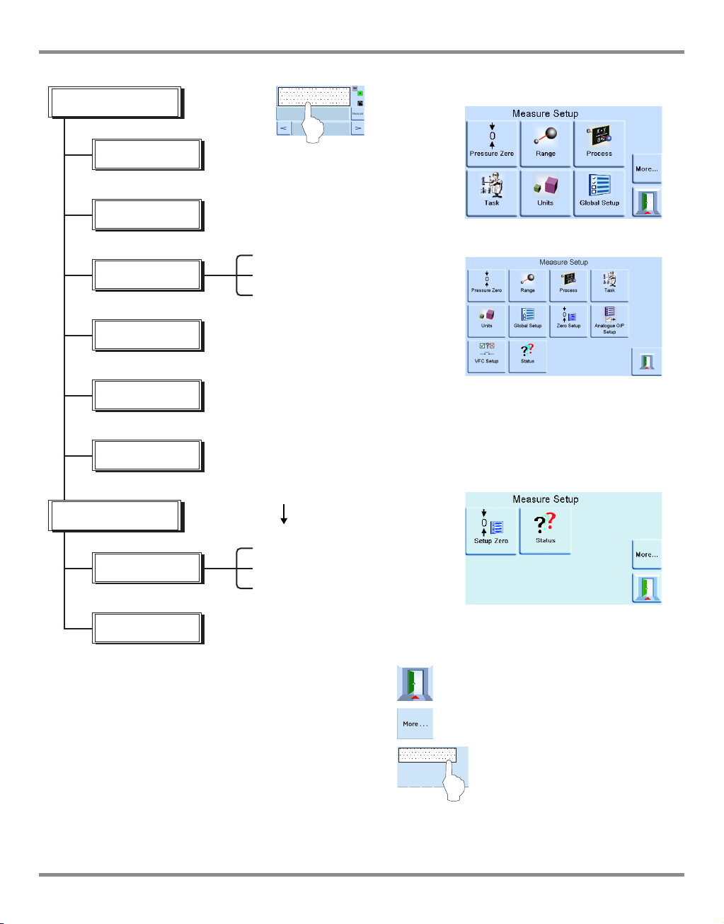
6.4 Measure Set-up
Pressure zero
During use, the instrument pressure sensor can show small zero shifts caused by time and
temperature changes. Regular “zeroing” increases measuring precision.
Process
Selects display processing features that change the reading, as follows:
%: Pressure can be expressed as a percentage of full-scale or as a percentage of a
specified span.
Filter: The reading can be filtered by a custom low pass filter or the filter can be disabled
(default disabled). The controller works at a speed independent of the filter time
constant.
Tare: A specific tare value can be selected or the current displayed pressure reading can
be “captured” as the tare value. The display shows the selected tare value in the
pressure window.
Task
Selecting Task enables a set of pre-determined functions and software enabled optional
functions.
Units
Select the new units from the list of pressure measurement units. Special units can also be
defined (Ref: Global set-up,
Section 6.6, supervisor set-up).
Global set-up
(Ref: Global set-up,
Section 6.6).
Set-up zero
Mode = off/auto/timed
Interval = 00.00.00
Isolation status = isolated/non-isolated.
[EN] English 6 - 9 K0443 Revision A
Page 63

6 Reference and Specification
6.5 Control Set-up
Vent
Select Vent to reduce the system pressure to near atmospheric pressure. Use this feature to
reduce system pressure to a safe value before disconnecting the UUT. Use vent set-up to
adjust the slew rate of venting.
Note: The vent key can be selected in the control set-up menu or programmed as an on-
screen selection in the status area from the global set-up/ display/status area menu.
Nudge
Sets the incremental resolution of the nudge control for trimming the set-point digits.
Set-point Limits
Defines the limits of pressure that can be entered as a set-point (used for protecting sensitive
UUT).
Slew rate
Sets how the controller achieves a set-point.
Max Rate Setpoint step changes to new setpoint
Linear: Controller changing pressure linearly to set-point at a rate set by user.
Rate: Either maximum rate or at a rate (value) set by user.
Overshoot: Fast changing pressure may go beyond set-point.
No overshoot: Changing pressure at an exponential rate but remaining within limits.
Note: This function should be used for UUT that have hysteresis errors.
Control mode
Selects one of the three modes that follow:
Active Control
In this mode, the controller continuously maintains the set-point, compensating for small
pressure leaks and thermal affects.
Passive Control
In this mode, the user can define a band either side of the set-point, the default band equals
to the instrument’s precision. When the controlled pressure enters this band, the controller
automatically shuts-off. If the measured pressure exits the band, the controller automatically
re-establishes the pressure, without instability, the controlled pressure re-enters the band.
Note: If passive mode is in use with a leak free and thermally stable system then the control
stability contribution can be discounted from the uncertainty calculation.
Zero Gauge Control
The controller switches off once stable at zero gauge and the zero valve opened. Entering a
new set-point causes the zero valve to close and the controller starts to control to the new
set-point.
K0443 Revision A 6 - 10 [EN] English
Page 64

PACE Pressure Controller User Manual
Global set-up
PIN protected menu (Ref: Supervisor set-up, Section 6.7).
Status
The display shows the following:
a. Instrument
• Module 1 (Module2 if fitted)
• Control sensor
• +ve source sensor
• -ve source sensor
• Barometric sensor (Optional)
b. Software build - read only data
c. Hardware build - read only data
d. History - read only data
e. Communications
f. Current set-up - read only data
g. Use log - read only data
h. Software options - read only data
i. Summary - read only data.
Vent set-up
Use the vent set-up to prevent damage to rate-sensitive equipment connected to this
controller. The vent slew rate setting is independent of the controller slew rate settings.
6.6 Global set-up Supervisor set-up
PIN protected menu (Ref: Supervisor set-up, Section 6.7).
Calibration
PIN protected menu.
Save/recall user set-up
Save user set-up
Recall user set-up
Display
Resolution
Backlight
Audio volume
Status area
Screen mode (PACE 6000 only)
[EN] English 6 - 11 K0443 Revision A
Page 65

6 Reference and Specification
6.7 Supervisor Set-up
The Supervisor menu provides facilities for programming settings. These are made during
installation as follows:
Important Note:
A PIN protects the Supervisor menu against unauthorised use. Each instrument on delivery
contains the factory set PIN (0268). To continue protecting the supervisor set-up menu the
PIN should be changed as soon as possible.
Protective Vent
The protective vent can be enabled or disabled and causes the discharge of pressure at a
controlled rate if the measured pressure exceeds 110% full-scale. This protects the pressure
sensor from over-range.
The Power-up trapped pressure vent can be enabled or disabled from the protective vent
menu.
In Limits
A tolerance value can be set at the set-point. When the controller achieves the set-point, the
instrument controls within this set tolerance value. It does not affect controller stability or
precision. The instrument uses the ‘in limits’ flag when performing a control task such as
Leak Test or Switch Test.
Note: In remote control, the control computer can be used to interrogate the ‘in limits’
register to confirm the controller has achieved set-point.
Alarms
An alarm can be set to trigger when the pressure exceeds the high alarm or falls below the
low alarm. A buzzer sounds when the alarm triggers and the alarm symbol (bell) appears on
the display.
Comms
Selects a communication port parameter. Simultaneous operation of both the RS232 and the
IEEE 488 interfaces is fitted as standard.
The user can select appropriate settings for communicating with the control computer (PC)
and the required command protocol. (Ref: K0472, SCPI Remote Communications Manual or
K0469 Heritage Communications Manual).
K0443 Revision A 6 - 12 [EN] English
Page 66

PACE Pressure Controller User Manual
RS232
Located on the rear panel an external RS232 connection requires the following:
Connector 9-way ‘D’ female wired as per Table 2-1
Communications RS232 point-to-point only
(DPI 520 daisy chain is not supported)
Baud Rate power-up default 9600, no parity & handshake = xon/xoff
Baud rates selectable ** 2400, 4800, 9600, 19k2, 38k4, 57k6 & 115k2
Parity None, Odd & Even
Flow control None, Hardware & xon/xoff
Protocols † SCPI, DPI 500, DPI 510, DPI 515, DPI 520
New data up-date rate refer to data sheet
Built-in EMC Filtering and Transient voltage protection
** Selectable through the user interface † Not all protocols available on all models.
IEEE 488
Located on the rear panel an external IEEE 488 connection requires: the following:
Connector 24-way ‘D’ female wired as IEEE 488 standard
Communications IEEE 488 GPIB
Default Address 16
Protocols † SCPI, DPI 500, DPI 510, DPI 515, DPI 520
New data up-date rate refer to data sheet
Built-in EMC filtering and transient voltage protection.
† Not all protocols available on all models.
Ethernet
Located on the rear panel an external Ethernet connection requires the following:
Connector Ethernet RJ45
Protocol SCPI
Terminator CR/LF
Default Address Auto IP (0.0.0.0)
Host name PACExxxxxx (where xxxxxx = serial number)
Web Password 0268
Access control Open
Reset LAN Settings Selected in Supervisor set-up menu
[EN] English 6 - 13 K0443 Revision A
Page 67

6 Reference and Specification
Ethernet Firewall
A firewall protects the Ethernet connection. The firewall is always turned on. The following
ports are unfiltered to allow remote communication and control.
Port Description
80/tcp http (Web server)
111/tcp rpcbind (RPC for VXI)
111/udp rpcbind (RPC for VXI)
443/tcp https (Web server)
5025/tcp SCPI socket
*****/tcp VXI-11 communication (dynamic port allocated)
Ethernet Parameters Range Setup
1. Touch any of the three horizontal Measure touch pads on the home screen to open the
CONTROL SET UP screen
2. On the CONTROL SETUP screen, select GLOBAL SETUP.
K0443 Revision A 6 - 14 [EN] English
Page 68

PACE Pressure Controller User Manual
3. Select SUPERVISOR SET UP.
4. Enter the Supervisor PIN and press ENTER SUPERVISOR PIN. Use the back arrow in the top
right corner of the screen to delete any incorrect data entries.
Note: The factory set Supervisor PIN is 0268. If the Supervisor PIN has been locally changed,
make sure that the new PIN is kept in a safe place. If the new PIN is lost, it can only
reset at a GE Service Centre.
[EN] English 6 - 15 K0443 Revision A
be
Page 69

6 Reference and Specification
5. Press COMMUNICATIONS STATUS to open the COMMUNICATIONS STATUS screen.
6. Select ETHERNET to open the ETHERNET PARAMETER screen.
7. To change the ADDRESS parameter, complete the following:
a. On the ETHERNET PARAMETER screen, use the UP and DOWN arrows to highlight
the ADDRESS field.
b. Press the top touch pad on the screen to enter the ADDRESS TYPE screen.
K0443 Revision A 6 - 16 [EN] English
Page 70

PACE Pressure Controller User Manual
c. Use the UP and Down arrows to highlight the desired address type (either AUTO IP
or STATIC).
d. Press the top touch pad on the screen to set the new address type. The screen
automatically returns to the ETHERNET PARAMETERS screen.
8. To change the host name, complete the following:
a. On the ETHERNET PARAMETER screen, use the UP and DOWN arrows on the right of
the screen to highlight the HOST NAME field.
b. Press the top touch pad on the screen to enter the HOST NAME screen.
c. Use the keyboard to input the new host name and then press the top button on the
screen to set the host name. The screen automatically returns to the ETHERNET
PARAMETERS screen.
[EN] English 6 - 17 K0443 Revision A
Page 71

6 Reference and Specification
9. To change the web password, complete the following:
a. On the ETHERNET PARAMETER screen, use the UP and DOWN arrows on the right of
the screen to highlight the WEB PASWORD field.
b. Press the top touch pad on the screen to enter the WEB PASSWORD screen. The
keyboard screen opens.
K0443 Revision A 6 - 18 [EN] English
Page 72

PACE Pressure Controller User Manual
c. Use the keyboard to input the new web password and then press the top touch
area on the screen to set the new password. The screen automatically returns to
the ETHERNET PARAMETERS screen.
10. To reset the LAN settings, complete the following:
a. On the ETHERNET PARAMETER screen, use the UP and DOWN arrows on the right of
the screen to highlight the RESET LAN SETTINGS field.
b. Press the RESET THE LAN SETTINGS touch pad on the top touch pad of the screen.
c. The RESET LAN SETTINGS sub-screen asking for confirmation of the reset. Press YES
to confirm reset of the LAN settings.
11. To turn the LAN status indicator on or off, complete the following:
a. On the ETHERNET PARAMETER screen, use the UP and DOWN arrows on the right of
the screen to highlight the SHOW LAN STATUS field.
[EN] English 6 - 19 K0443 Revision A
Page 73

6 Reference and Specification
USB
Located on the rear panel a USB connection requires the following:
Connector USB ‘B’
Protocol SCPI
Terminator CR, LR or CR/LF
Communications mode is selected for serial communications using the SCPI protocol.
Mass storage device is selected to mount an external USB ‘A’ connected mass storage
device or the internal memory SD card, from a PC connected to the USB ‘B’ port .
External USB device has priority masking the internal memory SD card.
Note: When upgrading software make sure USB ‘B’ connection is disconnected.
Timeout
Presets the times for automatically changing from control to measure mode.
Note: Controller timeouts can save supply gas, extending control valve life and minimising
acoustic noise.
K0443 Revision A 6 - 20 [EN] English
Page 74

PACE Pressure Controller User Manual
Reference
Level
Idle Timeout
Starts when the controller achieves the set-point after the
set time, if new set-points are not entered the timer will
time-out and return to measure mode.
Gas Head Correction
Corrects pressure output for the height difference
between instrument and UUT:
• For UUT positioned higher than the reference level of the PACE instrument enter a positive
height correction.
• For UUT positioned lower than the reference level of the PACE instrument enter a negative
height correction.
• When calibrating the PACE instrument disable the gas head correction and correct the
actual applied pressures for height.
Power Up
With Normal mode selected, the instrument powers up in Measure mode.
With regulator mode selected, the instrument powers-up in Control mode at a pre-selected
set-point value.
Note: When using regulator mode, disable the Idle Timeout feature.
Lock Tasks
Individual tasks
Allows any combination of individual tasks to be disabled.
Note: Restricts operation of the instrument to specific tasks or functions, use for production
procedures.
All
:
Disables all tasks.
Change PIN
Changes the Supervisor PIN: enter the existing PIN, then the new PIN and confirmation of the
new PIN.
Note: Confirmation of the new PIN permanently replaces the old PIN. Record this new PIN
and keep in a safe place. If new PIN is lost it can only be reset by returning the
instrument to a GE service centre.
User defined units
Permits the user to define a set of pressure conversion units. Following the on-screen
prompts special units may be set by selecting a Pascal multiplier and assigning a five
character name.
Instrument alias name
Permits the user to define a 20 character alias name for the instrument. The instrument
returns this name through the communications interfaces.
:
[EN] English 6 - 21 K0443 Revision A
Page 75

6 Reference and Specification
Language
Operation in any of the following languages can be selected:
•English (default)
•French
•German
•Italian
• Portuguese
• Spanish
• Russian
• Chinese
• Japanese More languages can be added.
Adding a Language
Languages can be added as follows (Ref: Figure 1, Language Setting)
1 Create a language file by translating from the English language file.
2 Check the pixel width of each translated word by using the PACE language check file,
(download from GE Support Central PACE).
3 Create an empty DPI folder on a USB stick.
4 Create an empty “LANGUAGES” sub-folder.
5 The language file naming conventions is “Language<<language name>>.lng”.
6 Save the language file into the languages sub-folder.
7 Use the PACE instrument software upgrade procedure to upload the language file
from the USB stick into the PACE instrument.
Note: An English and French language file name would be: LanguageEnglish.lng and
LanguageFrench.lng.
Language files named “Language.lng” or in any other format will be ignored by PACE.
K0443 Revision A 6 - 22 [EN] English
Page 76

PACE Pressure Controller User Manual
Figure 1 Language Setting
Restore as shipped settings
Restores instrument settings to factory default, but does not affect PIN settings.
[EN] English 6 - 23 K0443 Revision A
Page 77

6 Reference and Specification
Serial
number
6.8 Options Option enable process
To enable soft options on a PACE instrument, use the following:
1. Touch the top Measure area of the
screen.
2. Select Global Setup.
3. Select Calibration.
4. Enter a Calibration PIN 1234.
5. Enter new option key xxxxxxxxxx (10
digits).
6. After entry of this key PACE confirms
the options have been enabled.
Options in the Task Menu
The following software enabled options
can be selected from the task menu:
Leak Test option
This task applies one or two test pressures to either an external system to find any leaks in a
system connected to the instrument or an internal leak check. This task sets the test
pressure, control dwell time at the test pressure and the leak test time (measure dwell time).
K0443 Revision A 6 - 24 [EN] English
Page 78

PACE Pressure Controller User Manual
Example set-up parameter
Example leak rate results
Start
Test pressure 1
Leak test
Set-up
Test pressure 2
Edit pressure
Control dwell time
Measure dwell time
Leak rate
/second
/minute
T
P
TP 1
TP 2
Control
Dwell
Measure
Dwell
Control
Dwell
Measure
Dwell
End
Pressure
0
lk
lk
Note: If only one test pressure
is required set
TP1 = TP2.
At the start of the test, the
instrument applies a test
pressure to the user system.
A control dwell time allows the
user system to thermally
stabilise. The instrument
changes to measured mode
and then records the pressure
change during measure dwell
time. On completion, the
display shows the leak rate
results with leak rates per
second or per minute in the
current pressure units selected
in measure set-up.
lk = leak P = pressure T = Time (second) TP = test pressure
[EN] English 6 - 25 K0443 Revision A
Page 79

6 Reference and Specification
Example of setting a
parameter
Switch test
Switch test
Stop
Release pressure
Switch Test Parameter
Selection
Start
SUPPLY
OUTLET VENT REF
+-
Pressure Module
Pressure Switch
+
24V-0V
DC Output
Logic input
(24V max)
PACE
30Vmax
Switch Test option
This function automates the testing of
pressure switch devices. Connect the
pressure port of the switch to be tested to
the output port. Connect the switch
contacts in series with the 24V dc output
and the Logic Input.
Note: The volt-free logic input connections
require a switching potential (24V max) to
be applied. If necessary, this can be an
external d.c. source. Common mode must
be kept within 30V maximum.
Start
Controls pressure at a fast slew rate to a
set-point just below expected switch
operating point. De-bounce time can be
increased for slower test slew rates.
Test
Controls pressure between two set-points and can repeat (loop). Auto-reverse can be selected.
End
Controls pressure to a safe condition to disconnect switch under test.
Procedure
Select the switch test parameters in the switch test menu, including the start pressure, end
pressure and test rate of change. Slower rates give more accurate results. The de-bounce time can
be set between 0 and 200 ms.
After the test, the display shows the pressures at which the contacts open and close and the
switch hysteresis (the difference between the two switching pressures).
Before disconnecting the switch under test,
press Release pressure to release any
residual pressure.
Note: This switch test procedure can be
repeated to “exercise” the switch unit.
Logic input is opto-isolated. An external
supply (5V to 24V dc) can be used provided its’
common mode voltage remains with 30V
max with respect to chassis.
Example Switch Test Connections
K0443 Revision A 6 - 26 [EN] English
Page 80

PACE Pressure Controller User Manual
Run
Test program
<...new...>
File name
Stop
Start
single step
Copy
Delete
Edit
Select a test program
from list
Test Program option
The test program task provides a facility for writing and executing test procedures. Selecting
a test program from the Task menu displays all the task programs currently stored, together
with the ability to write new ones.
[EN] English 6 - 27 K0443 Revision A
Page 81

6 Reference and Specification
Program
To start a test program do the following:
1. Select the test programs listed on the screen.
2. The step function moves down the list of available test programs.
3. To start a test program, press run.
4. When the program starts, a stop legend replaces the run legend.
5. Press the stop key at any time to stop the test program.
To write a test program do the following:
1. Press Set-up.
2. Select New.
Note: A new test always contains a START and END command (first and last line instructions),
these lines cannot be deleted.
To edit an existing program do the following:
1. Press Edit.
To enter a name for the program do the following:
1. Use g the text editor keys to select letter range to select the letter within the range.
2. Use the right arrow key to move to the next character position.
3. Press enter on completion.
The display shows the line instruction with insert and delete selections. Pressing insert
changes the display to a list of the available programming commands.
Test programs can be saved to or uploaded from a USB stick.
Test programs can also be edited or written on a PC.
K0443 Revision A 6 - 28 [EN] English
Page 82

PACE Pressure Controller User Manual
Table 6-2 - Test Program Commands
Command Description
BEEP Beep on/off.
BREAK
CONTROL Selects Control mode.
COUNT Used in a loop to count the number of loop cycles.
DWELL Specifies dwell time (seconds).
GOTO Used to set-up a loop. Enter program line number to go to.
IN_LIMITS In_Limits band setting (% full-scale).
IN_LIMITS_TIME
IP_LOGIC Specifies change of state for external contacts as a halt condition.
MEASURE Selects Measure mode.
PAUSE Causes test program to pause for user input (Resume)
RANGE Specifies instrument range
RATE_MAX Sets controller rate to maximum.
RATE_VALUE Specifies controller rate.
RESOLUTION Sets display resolution.
SETPOINT Allows set-point to be entered.
SETTLING_FAST Used to specify overshoot requirements.
SETTLING_N_O Used to specify no overshoot.
STOP_COUNT Used to stop loop program after a number of loops.
TEXT Sets screen message.
UNITS Selects required display units.
VENT Instructs instrument to vent.
VFC OFF Sets VFC allocation test program off.
VFC ON Sets VFC allocation test program on.
WAIT_IN_ LIMITS Waits until pressure is within the limits.
ZERO Output zeroed
Breaks to this point when stop count command or STOP icon is selected, then
executing code to the end.
Waits, within In_Limits for this time period, before setting a valid In_Limits
condition.
To select a command, use the command on the display and press insert key to write it into
the program. Place the UNITS, RATE, SETTLING and RESOLUTION commands at the start of
the program this protects pressure-sensitive UUT.
When selected, certain commands require a value or selection to be set (e.g.) RANGE, RATE,
TEXT the display shows a screen prompt for the appropriate setting.
[EN] English 6 - 29 K0443 Revision A
Page 83

6 Reference and Specification
Example Program
Note: Changes to instrument settings made in a test program remain valid only for the test
program.
The instrument reverts to the pre-test settings on completion.
Step Command Argument Action
START Program start
1
UNITS mbar Select units, mbar
2
RATE 100 Select rate, 100 mbar/min
3
IN LIMITS TIME 10 (00:00:10) secs
4
IN LIMITS Set In Limits Band
5
RESOLUTION 5 Display resolution, 5 digits
6
SETTLING No overshoot
7
TEXT Operator instruction, e.g.”Connect UUT”
8
ZERO
9
SET-POINT 400 Set-point, 400 mbar
10
CONTROL Controller ON
11
WAIT IN LIMITS Wait for In Limits Condition
12
BEEP Beep on, approx. 1 sec, Beep off
13
MEASURE Switch to Measure (controller off)
14
DWELL 30 Wait for 30 sec (00:00:30)
15
SET-POINT 800 Set-point, 800 mbar
16
CONTROL Controller on
17
WAIT IN LIMITS Wait for In Limits Condition
18
BEEP ON Beep on, approx. 1sec, Beep off
19
MEASURE Switch to Measure (controller off)
20
TEXT
21
DWELL 30 Wait for 30 sec
22
BEEP Beep on, approx. 1 sec, Beep off
23
TEXT Operator instruction, e.g. “Min pressure allowed 785 mbar”
24
PAUSE WAIT, (for operator input to touch single step)
25
VENT Vent
END Program end
Operator instruction, e.g. (Wait for beep, record pressure)
K0443 Revision A 6 - 30 [EN] English
Page 84

PACE Pressure Controller User Manual
Programming Loops
To program a loop, use the GOTO command.
Include the COUNT command in the loop for counting the number of loop cycles.
Note: The test program commands do not include tests for conditional jumps.
To stop a test program from looping, STOP must be selected by the operator.
Example of programming a loop
Step Command Argument Action
START Program start
1
2
3
4
5
6
7
8
9
10
11
12
13
14
15
16
17
18
19
20
21
22
UNITS mbar Select units, mbar
RATE_VALUE 100 Select rate 100mbar/min
RESOLUTION 5 Display resolution 5 digits
IN LIMITS Sets the In-limits band
IN LIMITS TIME 10 (00:00:10) secs
SETTLING_N_O zero No overshoot
TEXT Operator instruction, e.g.“Connect UUT”
ZERO Performs a sensor zero
SET-POINT 400 Set-point, 400 mbar
CONTROL Controller ON
WAIT IN LIMITS Wait for In-limits condition
BEEP ON Beep on, approx. 1sec, Beep off
MEASURE Switch to measure (controller off)
DWELL 30 Wait, 30 sec
SET-POINT 800 Set-point, 800 mbar
CONTROL Controller on
WAIT IN LIMITS Wait for In-limits condition
BEEP ON Beep on, approx. 1sec, Beep off
MEASURE Switch to measure, controller off
COUNT Increment loop counter
VENT Vent
GOTO 9 Loop back to program line 9
END Program end
[EN] English 6 - 31 K0443 Revision A
Page 85

6 Reference and Specification
Barometric Pressure
2bar abs +1bar g
-1bar g
11bar abs
+10bar g
1350mbar abs
650mbar abs
0bar abs (Absolute Zero Pressure)
+350mbar g
-350mbar g
1070mbar abs
930mbar abs
+70mbar g
-70mbar g
Gauge reference pressure
70mbar Control Module with Barometric Option
Gauge Range = ±70mbar g
Pseudo Absolute Range = 930mbar abs to 1070mbar abs
350mbar Control Module with Barometric Option
Gauge Range = ±350mbar g
Pseudo Absolute Range = 650mbar abs to 1350mbar abs
10bar Control Module with Barometric Option
Gauge Range = -1bar g to +10bar g
Pseudo Absolute Range = 0bar abs to 11bar abs
1bar Control Module with Barometric Option
Gauge Range = ±1bar g
Pseudo Absolute Range = 0bar abs to 2bar abs
Barometric Reference Option
The barometric reference option measures the barometric pressure at the reference port.
When installed, this option allows absolute or gauge pressure range selection. To obtain
absolute pressure the instrument uses a summation of gauge pressure and barometric
pressure (measured by the barometric sensor).
Ref: Data sheet 920-561 for the barometric reference and precision of absolute ranges.
K0443 Revision A 6 - 32 [EN] English
Page 86

PACE Pressure Controller User Manual
Aeronautical option
The aeronautical option is a specialised application of the PACE instrument.
Special application note: The PACE instrument must be set-up very carefully so that the
aeronautical pressures applied do not exceed maximum pressure values and rates of
change.
Leak testing
Cautions
Do not exceed the maximum pressures stated in the appropriate Component
Maintenance Manual for the unit under test.
Carefully de-pressurize all pipes to atmospheric pressure before disconnecting and
connecting to the unit under test.
Before testing an aeronautical component do a leak test.
This task sets the test pressure, dwell time at the test pressure and the leak test time.
At the start of the test, the instrument applies a test pressure to the user system.
A dwell time allows the user system to stabilise.
Aeronautical testing
The aeronautical task enables control and measurement of the following:
• Altitude (feet/metres)
• Airspeed (knots, mph, km/h)
This task utilises dual pressure displays to show the parameter and the rate of change of the
following:
•Altitude
•Airspeed
• Mach and Airspeed with Mach number
The aeronautical task enables the testing and calibration checking of aeronautical
indicators and system components by controlling and displaying values and rates in
aeronautical units.
When using a single instrument, the pressure supply must be changed when changing from
[EN] English 6 - 33 K0443 Revision A
Page 87

6 Reference and Specification
SUPPLY
OUTLET VENT REF
+-
Module 2
SUPPLY
OUTLET VENT REF
+-
Module 1
Rear view of
instrument
SUPPLY
OUTLET VENT REF
+-
Module 2
SUPPLY
OUTLET VENT REF
+-
Module 1
Altimeter ASI/Mach
Pt Ps
Qc
Rear view of
instrument
Pitot Static
Open to Atmosphere
Altitude to Airspeed.
Example of Altitude and Airspeed Testing
This example shows how two-channel PACE instruments can be used to generate altitude
and airspeed.
Cautions
Before testing, set the rates of change for both Pitot and Static to a safe value. A high
rate of change can damage sensitive aeronautical components. Refer to the appropriate
Component Maintenance Manual for the unit under test.
In this example configuration, negative airspeed can be generated this can damage an
airspeed indicator. To prevent negative airspeed, apply the Static pressure before the
Pitot pressure for increasing and decreasing airspeed values.
K0443 Revision A 6 - 34 [EN] English
Page 88

PACE Pressure Controller User Manual
SUPPLY
OUTLET VENT REF
+-
Module 2
SUPPLY
OUTLET VENT REF
+-
Module 1
Pressure
source
Pressure
regulator
Pressure
regulator
Rear view of
PACE
instrument
Vacuum
source
Altimeter
ASI/Mach
Static Static
Pitot
Pitot Static (Altitude)
Units
The units can be either the aeronautical or pressure units. The units can be changed any
time between pressure and pressure converted to aeronautical units. The display shows the
output pressure converted to Altitude, CAS or Mach using BS 2G 199:1984* conversions and
assuming standard atmospheric conditions.
*Based on tables from ICAO Standard Atmosphere 1964. Reference Pressure
Select the required reference pressure, this can be either the barometric pressure (from the
instrument’s internal barometric sensor), or any numeric value (e.g.) 1013.25 mbar.
Go to ground
Returns the instrument and any UUT, connected to it, safely to ground pressure at a
controlled rate.
[EN] English 6 - 35 K0443 Revision A
Page 89

6 Reference and Specification
Control of Aeronautical parameters
The aeronautical control is an intergrated controller. The two modules work together as a
dual channel pressure controller (Ref: Figure 1, Screen Layout).
In aeronautical mode, the display goes to the last selected parameter:
•Altitude
•Airspeed
•Mach
K0443 Revision A 6 - 36 [EN] English
Page 90

PACE Pressure Controller User Manual
1
Figure 1 Screen Layout
In dual screen mode both altitude and airspeed controllers are set to control mode, by
selecting the Enter Control key (Ref: Figure 1, Screen Layout).
The Enter Measure key sets both controllers to measure mode. (Ref: Figure 1, Screen Layout).
(Ref: Figure 1, Item 1,Screen Layout) if this is selected both controllers will go to ground.
Figure 2 Measurement mode
[EN] English 6 - 37 K0443 Revision A
Page 91

6 Reference and Specification
1
1
(Ref: Figure 2, measurement mode) both controllers in measurement mode.
Figure 3 Control mode
(Ref: Figure 3, Control mode) both controllers in control mode.
In control mode each control can have an individual set-point.
If Hold is selected (Ref: Figure 3, Item 1, Control mode) a set altitude or speed will be held.
Note: The altitude and airspeed controllers are still actively ON, but held at the selected
range.
Figure 4 Set-points
If Resume is selected (Ref: Figure 4, Item 1, Set-points) the altitude and speed will continue to
the set-points.
K0443 Revision A 6 - 38 [EN] English
Page 92

PACE Pressure Controller User Manual
Selects Analogue
Output Range
On/Off
Update rate of Analogue Output
option from the control module.
Analogue Output Bandwidth = 0.5 x Update Rate (Hz)
analogue connections
30V maximum with respect to
chassis.
Rated output = 24V
30Vmax
To maintain PACE product safety, external
circuits connected to the instrument must meet
Safety Extra-Low Voltage (SELV) requirements.
15-way female D connector
Front view of Analogue
Option PCB connector
123
4
5
6
7
8
15 14 13 12 11 10 9
30Vmax
Analogue Output Option
The analogue output option provides a selectable output of voltage or current.
Pin number Function Pin number Function
1 not used 9 not used
2 not used 10 0V return
3 not used 11 +24V DC OUT @ 100mA
4 not used 12 SW IN 1
5 not used 13 SW IN 2
6 not used 14 analogue +
7 not used 15 analogue -
8not used
[EN] English 6 - 39 K0443 Revision A
Page 93

6 Reference and Specification
Each selection has
three Volts-free
Contacts.
Selection of trigger
conditions.
Selection of trigger
conditions.
volts-free connections
30V maximum with respect to
chassis.
Rated output = 24V
30Vmax
To maintain PACE product safety, external
circuits connected to the instrument must meet
Safety Extra-Low Voltage (SELV) requirements.
0V
+V
event
trigger
24 Vdc maximum
30 Vdc wrt chassis
1 A resistive maximum
Typical Volts-free
schematic
Relay contacts rated at 30 Vdc, 1 A resistive,
200 mA inductive.
Volts-free Contact Option
The Volts-free Contact option provides a selectable output of voltage or current.
Pin number Function Pin number Function
1 Relay 1 normally CLOSED 9 Relay 3 common
2 Relay 1 normally OPEN 10 0V return
K0443 Revision A 6 - 40 [EN] English
3 Relay 1 common 11 +24V DC OUT @ 100mA
4 Relay 2 normally CLOSED 12 SW IN 1
5 Relay 2 normally OPEN 13 SW IN 2
6 Relay 2 common 14 not used
7 Relay 3 normally CLOSED 15 not used
8 Relay 3 normally OPEN
Page 94

PACE Pressure Controller User Manual
6.9 Calibration
The calibration menu provides facilities for programming settings for maintenance as
follows:
Note: A PIN protects the Calibration menu against unauthorised use. Each instrument, on
delivery, contains the factory set PIN (4321). To continue protecting the supervisor setup menu, the PIN should be changed as soon as possible.
+ve source zero
-ve source zero
sensor correction Selects the range for a three-point calibration routine.
valve correction
source PDCR correction three-point calibration of both source pressure sensors
screen calibration
Time & Date Sets instrument clock and calendar.
Change PIN Changes the Calibration PIN. Enter the existing PIN, the new PIN and
confirmation of the new PIN. Should this new PIN become lost it can
only be reset by returning the instrument to a GE service centre.
6.10 Communications - Instrument Emulation
(Ref: K0469 - PACE Communications Manual - Instrument Emulation).
6.11 Specification
(Ref: PACE Module Pressure Controller data sheet).
Note: Data sheet 920-561 is contained in the CD shipped with the product.
6.12 Return Goods/Material Procedure
If the unit requires calibration or is unserviceable return it to the nearest GE Service Centre
listed at www.gemeasurement.com.
Contact the Service Department, by 'phone, fax or E-mail to obtain a Return Goods
Authorisation (RGA) (Worldwide excluding USA).
In the USA obtain a Return Material Authorization [RMA].
• Product (i.e. PACE5000)
• Serial number
• Details of defect/work to be undertaken
• Calibration traceability requirements
• Operating conditions
[EN] English 6 - 41 K0443 Revision A
Page 95

6 Reference and Specification
Safety Precautions
You must inform GE if the product has been in contact with any hazardous or toxic
substance.
The relevant COSHH or in the USA, MSDS, references and precautions to be taken when
handling.
Important notice
Service or calibration by unauthorized sources will affect the warranty and may not
guarantee further performance.
6.13 Packaging Procedure
1 The instrument should be at zero/ambient pressure.
2. Switch off and isolate the electrical power supply to the instrument.
3. Shut off the pneumatic pressure and vacuum supplies to the instrument.
4. Remove the instrument from the equipment rack to access the rear panel.
5. Disconnect the power supply cable and the pneumatic supply hose assemblies.
6. Stow the power supply cable in the packaging below.
7. Remove any pressure adaptors, diffusers and restrictors.
If available, use the original packing material. When using packing materials other than the
original, do the following:
8. Fit protection to all the ports to prevent ingress of moisture and dirt.
Note: Use the original red plastic plugs or low tack masking tape.
9. Wrap unit in polyethylene sheeting.
10. Select a double-wall cardboard container.
• Inside dimensions must be at least 15 cm (6”) greater than the equipment
• The carton must meet test strength requirements of >
11. Protect all sides with shock-absorbing material to prevent equipment movement
within the container.
12. Seal carton with approved sealing tape.
13. Mark carton “FRAGILE” on all sides, top, and bottom of shipping container.
Environment
The following conditions apply for both shipping and storage:
• Temperature range: -20° to +70°C (-4° to +158°F)
125 kg (275 lbs).
K0443 Revision A 6 - 42 [EN] English
Page 96

PACE Pressure Controller User Manual
6.14 Vacuum System Parts
The parts list below lists a typical system to supply vacuum, enabling the control of subatmospheric pressures by the PACE instrument. Part numbers quoted in the table are taken
from the BOC Edwards Vacuum Products Catalogue. For more information, go to:
www.bocedwards.com.
Description Part Number Quantity
RV5 115/230Vac Vacuum Pump, 91 litre/min
EMF10 Mist Filter
NW25/NW10 Reducer fitting
NW10 T-Piece Fitting
IPVA10EK Air Admittance Valve, Normally Open
NW10 Flexible Pipeline 1m, S/S
NW10 Clamping Ring
NW10 Centering Ring
NW25 Clamping Ring
NW25 Centering Ring
NW16/10 Centering Ring
NW16 to ¼NPT Male Adapter, S/S
FL20K Foreline Trap
A653-01-903 1
A462-26-000 1
C105-14-436 2
C105-11-411 1
C417-21-000 1
C105-11-287 4
C105-12-401 5
C105-11-398 5
C105-14-401 3
C105-14-398 3
C105-12-349 1
C105-01-103 1
FL-20-K 1
[EN] English 6 - 43 K0443 Revision A
Page 97

6 Reference and Specification
Intentionally Blank
K0443 Revision A 6 - 44 [EN] English
Page 98

www.gemeasurement.com
 Loading...