


|
|
|
MANUAL TRANSMISSION - GETRAG 238 - SERV |
|
DR |
|
|||
MANUAL TRANSMISSION - GETRAG 2 |
||||
|
|
|
INFORMATION |
|
|
|
|
TABLE OF CONTENTS |
|
|
|
|
page |
page |
MANUAL TRANSMISSION - GETRAG 238 - SERVICE INFORMATION
DIAGNOSIS AND TESTING
MANUAL TRANSMISSION - GETRAG 238 . . . . . 70 STANDARD PROCEDURE
DRAIN AND FILL . . . . . . . . . . . . . . . . . . . . . . . . . . . . 70 REMOVAL . . . . . . . . . . . . . . . . . . . . . . . . . . . . . . . . . . . . 71 DISASSEMBLY . . . . . . . . . . . . . . . . . . . . . . . . . . . . . . . 73
CLEANING . . . . . . . . . . . . . . . . . . . . . . . . . . . . . . . . . . . 99 INSPECTION . . . . . . . . . . . . . . . . . . . . . . . . . . . . . . . . . 99 ASSEMBLY . . . . . . . . . . . . . . . . . . . . . . . . . . . . . . . . . . 102 INSTALLATION . . . . . . . . . . . . . . . . . . . . . . . . . . . . . . 134 SPECIFICATIONS
MANUAL TRANSMISSION - GETRAG 238 . . . . 135 SPECIAL TOOLS . . . . . . . . . . . . . . . . . . . . . . . . . . . . 137
21 - 70 MANUAL TRANSMISSION - GETRAG 238 - SERVICEDR
MANUAL TRANSMISSION - GETRAG 238 - SERVICE INFORMATION
DIAGNOSIS AND TESTING
MANUAL TRANSMISSION - GETRAG 238
LOW LUBRICANT LEVEL
A low transmission lubricant level is generally the result of a leak, inadequate lubricant fill or incorrect lubricant level check.
Rear transmission leaks will be from the oil seals or transfer case front seal on 4x4.
Front transmission leaks will be from the front input shaft retainer seal. Lubricant may drip from the clutch housing after extended operation. If leak is severe, it may contaminate the clutch disc.
Lubricant level check can only be made when the vehicle is level and allowing the lubricant to settle for a minute before checking. This will ensure an accurate check and avoid an under or overfill condition.
HARD SHIFTING
Hard shifting can be caused by low lubricant level, improper or contaminated lubricants. This will cause noise, excessive wear, internal bind, and hard shifting. Substantial lubricant leaks can result in gear, shift rail, synchro, and bearing damage. The first indications of component damage is usually hard shifting and noise.
Shift component damage, clutch adjustment, worn pressure plate or disc, can increased shift effort. If clutch problem is advanced, gear clash during shifts can result. Worn or damaged synchronizer rings can cause gear clash when shifting into any forward gear. In some new or rebuilt transmissions, new synchro rings may tend to stick slightly causing hard or noisy shifts. In most cases, this condition will decline as the rings wear-in.
TRANSMISSION NOISE
Most manual transmissions make some noise during normal operation. Rotating gears generate a mild whine that is audible, but generally only at extreme speeds.
Severe, highly audible transmission noise is generally the initial indicator of a lubricant problem. Insufficient, improper or contaminated lubricant will promote rapid wear of gears, synchronizer rings, shift rails, forks and bearings. The overheating caused by a lubricant problem, can also lead to gear and bearing damage.
STANDARD PROCEDURE
DRAIN AND FILL
1.Raise and support vehicle.
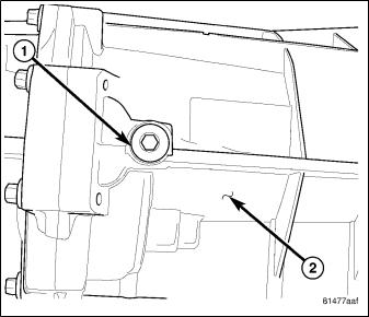
2.Remove drain plug (1) on transmission (2) and drain fluid.
3.Install drain plug and tighten to 50 N·m (37 ft. lbs.).

4.DRRemove fill plug (1) from side of transmission (2).
5.Fill transmission even with the bottom of the fill
hole.
6. Install fill plug and tighten to 50 N·m (37 ft. lbs.).
REMOVAL
1.With vehicle in neutral, position vehicle on hoist.
2.Disconnect battery negative cable.
3.Remove shift boot bezel screws and slide boot upward on shift lever extension.
4.Remove shift lever extension from the shift tower and lever assembly.
5.Remove 4WD shift boot if equipped and remove floor console.
6.Remove skid plate, if equipped.
7.Remove drain plug (1) from rear housing (2) and drain fluid.
8.Mark propeller shaft/shafts and companion flange yoke/yokes for installation reference and remove propeller shaft/shafts.
9.Disconnect harness from clips on transmission housing.
10.Remove transfer case linkage if equipped.
11.Remove transfer case mounting nuts and remove transfer case if equipped.
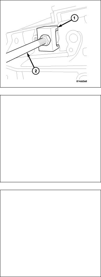
12.Remove slave cylinder (2) mounting nut (1) and remove cylinder.
21 - 72 MANUAL TRANSMISSION - GETRAG 238 - SERVICEDR
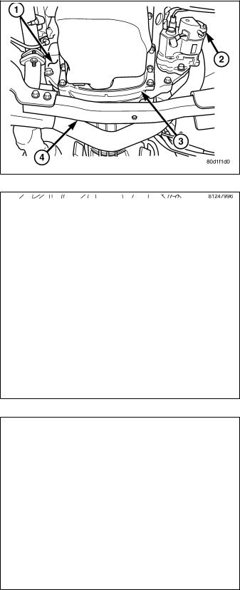
13.Remove starter motor (2), structural dust cover (3) bolts to clutch housing, dust shield (1) bolt and suspension crossmember (4).
CAUTION: Do not remove structural dust cover from engine block. If cover is removed clutch housing and cover must be aligned with the engine.
14.Remove exhaust pipe from the exhaust manifolds.
15.Support engine with adjustable jack stand and wood block.
16.Support and secure transmission (1) to a transmission jack (2) with safety chains.
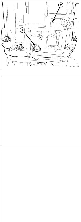
17.Remove bolts from the rear transmission mount.
18.Remove the rear crossmember (2) and transmission mount (1).
19.Remove bolts attaching transmission to the engine.
20.Move transmission rearward until input shaft is clear of clutch disc and pressure plate. Then lower jack and remove transmission from under vehicle.

DR |
MANUAL TRANSMISSION - GETRAG 238 - SERV |
DISASSEMBLY |
|
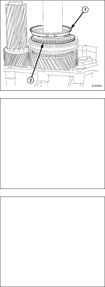
1. Remove shifter socket (1) from main shift rail.
2.Remove back up lamp switch (1) bolt (2) and remove switch.
21 - 74 MANUAL TRANSMISSION - GETRAG 238 - SERVICEDR
3.Remove large detent plug, next to back up lamp switch opening with Puller 9583 (1) and Slide Hammer C-3752 (2).
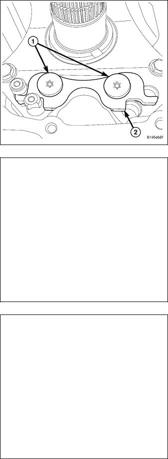
4.Remove two small detent plugs on top of rear housing with Puller 8870 (2) and Slide Hammer C-3752 (1).
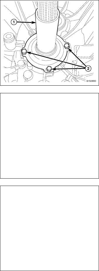
5. Install Wrench 9586 (1) on input shaft (2).

DR
6. Remove output flange (1) nut (2) on 4x2 transmission.
7.Remove output flange (1) on 4x2 transmission with Puller 8992 (2) and Button 9618-2.
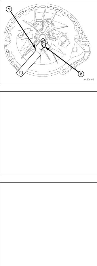
8.Remove output shaft nut with Socket 9584 (1) on 4x4 transmission (2).
9.Remove Wrench 9586 from input shaft.
21 - 76 MANUAL TRANSMISSION - GETRAG 238 - SERVICEDR
10.Place transmission on front housing and remove rear housing (2) bolts (1). If necessary, remove the cover plate to access the one rear housing (2) bolt (1) located in the opening.
11. Install Button 9618-2 (1) into output shaft (2).
12.Separate rear housing (1) from mainshaft with Puller 9621(2). Bolt puller to the bottom of the rear housing, then turn puller bolt to push mainshaft out of the housing.

DR
13. Remove reverse shift fork roll pin (1) from reverse shift rail (2).
14.Slide reverse shift rail (1) down out of the shift fork (2) and remove reverse shift fork. Then slide shift rail up and out of the front housing.
15.Remove 1-2 shift fork roll pin (1) from shift rail (2). Slide shift rail up out of shift fork and rear housing. Remove 1-2 shift fork.

21 - 78 MANUAL TRANSMISSION - GETRAG 238 - SERVICEDR
16.Rotate main shift rail (1) clockwise and pull up and out of the front housing.
17.Remove first gear, reverse gear, reverse bearing, reverse gear bearing race and reverse synchronizer with Bridge 938 (1), Button 9618-2 (2) and puller Adapters 9628 (3). Position puller Adapters 9628 (3) under first gear.
DR
18. Remove first gear bearing (1) from mainshaft (2).
19.Remove first gear synchronizer inner friction ring
(1)from 1-2 synchronizer hub (2).
20.Remove first gear synchronizer outer friction ring
(1)from 1-2 synchronizer hub (2).
21 - 80 MANUAL TRANSMISSION - GETRAG 238 - SERVICEDR
21.Remove first gear synchronizer blocker ring (1) from 1-2 synchronizer hub (2).
22. Remove 1-2 synchronizer hub (1) snap ring (2).
23.Remove 1-2 synchronizer sleeve (1) from 1-2 synchronizer hub (2).

DR |
MANUAL TRANSMISSION - GETRAG 238 - SERV |
||
|
|
|
|
24. Remove 1-2 synchronizer hub (1) detents (2). |
|
|
|
|
|
|
|
25.Remove second gear and 1-2 synchronizer hub with Bridge 938 (1), Button 9618-2 (2) and Adapters 9627 (3).
21 - 82 MANUAL TRANSMISSION - GETRAG 238 - SERVICEDR
26.Remove interlock plate bolts (1) and remove interlock plate (2).
27. Remove washers (1) from intermediate plate (2).
28. Remove intermediate plate (1) bolts (2).

DR
29. Remove intermediate plate (1) dowels (2) with a suitable tool and remove intermediate plate.
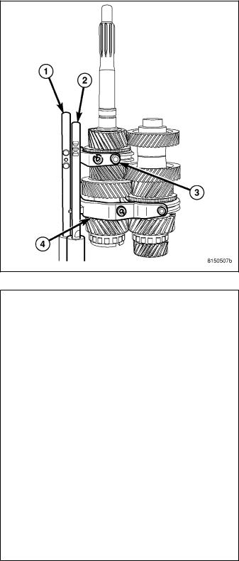
30.Install Fixture 9626 (2) on main/countershaft and shift rails. Turn fixture (2) with transmission (1) over onto the fixture.
21 - 84 MANUAL TRANSMISSION - GETRAG 238 - SERVICEDR
31.Remove clutch release bearing support bolts (2) and retainer (1).
32.Insert seal Puller 9667 through one input shaft seal (1) disassembly hole (2).
33.Remove input shaft seal with Remover 9667 (1) and Slide Hammer C-3752 (2).

DR |
MANUAL TRANSMISSION - GETRAG 238 - SERV |
||
|
|
|
|
34. Remove input shaft (1) snap ring (2). |
|
|
|
|
|
|
|
35.Put a hole in the center of the countershaft plug
(2)with a punch (1).
36.Remove countershaft plug (1) from front housing with Puller 9667 (2) and Slide Hammer C-3752.
21 - 86 MANUAL TRANSMISSION - GETRAG 238 - SERVICEDR
37. Install Wrench 9586 (1) on input shaft (2).
38.Remove countershaft allen bolt (1).
39.Remove input shaft wrench.
40.Remove two detent plugs from the side of the housing with Puller 8870 (1) and Slide Hammer C-3752 (2).

DR
41. Remove 3-4 (2) and 5-6 (1) shift fork pivot bolts from both sides of the front housing.
42.Install Puller 9621(1) with puller Plug 9621-2 (2) on front housing. Tighten puller bolts evenly and remove front housing from the mainshaft and countershaft.
21 - 88 MANUAL TRANSMISSION - GETRAG 238 - SERVICEDR
43.Remove 5-6 shift fork (3) and 3-4 shift fork (4). Then remove 5-6 shift rail (1) and 3-4 shift rail (2) from Fixture 9626.
44. Remove input shaft (1) from mainshaft (2).
DR |
MANUAL TRANSMISSION - GETRAG 238 - SERV |
||
|
|
|
|
45. Remove input shaft bearing (1) from mainshaft |
|
|
|
(2). |
|
|
|
|
|
|
|
46. Remove countershaft (2) from fixture (3).

21 - 90 MANUAL TRANSMISSION - GETRAG 238 - SERVICEDR
MAINSHAFT
1.Remove fifth gear synchronizer clutch body (1) from 5-6 synchronizer hub (2).
2.Remove fifth gear synchronizer friction ring (1) from 5-6 synchronizer hub (2).
 Loading...