


DR AUTOMATIC TRANSMISSION - 545RFE - ELECT
AUTOMATIC TRANSMISSION - 545R
DIAGNOSTICS
TABLE OF CONTENTS
page
AUTOMATIC TRANSMISSION - 545RFE - ELECTRICAL DIAGNOSTICS
DIAGNOSIS AND TESTING
P0122-TPS/APP CIRCUIT LOW . . . . . . . . . . . . . 581 P0123-TPS/APP CIRCUIT HIGH . . . . . . . . . . . . . 584 P0124-TPS/APP INTERMITTENT . . . . . . . . . . . . 586 P0218-HIGH TEMPERATURE OPERATION
ACTIVATED . . . . . . . . . . . . . . . . . . . . . . . . . . . . . . 588 P0562-BATTERY VOLTAGE LOW . . . . . . . . . . . . 589 P0602-CONTROL MODULE PROGRAMMING
ERROR/NOT PROGRAMMED. . . . . . . . . . . . . . 594 P0604-INTERNAL CONTROL MODULE RAM . 595 P0605-INTERNAL CONTROL MODULE ROM . 596 P0613-INTERNAL TCM . . . . . . . . . . . . . . . . . . . . . 597 P0706-TRANSMISSION RANGE SENSOR
RATIONALITY . . . . . . . . . . . . . . . . . . . . . . . . . . . . 598 P0711-TRANSMISSION TEMPERATURE
SENSOR PERFORMANCE. . . . . . . . . . . . . . . . . 602 P0712-TRANSMISSION TEMPERATURE
SENSOR LOW. . . . . . . . . . . . . . . . . . . . . . . . . . . . 605 P0713-TRANSMISSION TEMPERATURE
SENSOR HIGH . . . . . . . . . . . . . . . . . . . . . . . . . . . 608 P0714-TRANSMISSION TEMPERATURE
SENSOR INTERMITTENT. . . . . . . . . . . . . . . . . . 611 P0715-INPUT SPEED SENSOR 1 CIRCUIT . . . 614 P0720-OUTPUT SPEED SENSOR CIRCUIT . . 620 P0725-ENGINE SPEED SENSOR CIRCUIT . . . 626 P0731-GEAR RATIO ERROR IN 1ST . . . . . . . . . 628 P0732-GEAR RATIO ERROR IN 2ND . . . . . . . . 631 P0733-GEAR RATIO ERROR IN 3RD . . . . . . . . 637 P0734-GEAR RATIO ERROR IN 4TH . . . . . . . . 643 P0735-GEAR RATIO ERROR IN 5TH . . . . . . . . 647 P0736-GEAR RATIO ERROR IN REVERSE . . . 650 P0740-TCC OUT OF RANGE . . . . . . . . . . . . . . . . 653 P0750-LR SOLENOID CIRCUIT . . . . . . . . . . . . . 655 P0755-2C SOLENOID CIRCUIT . . . . . . . . . . . . . 659 P0760-OD SOLENOID CIRCUIT . . . . . . . . . . . . . 663 P0765-UD SOLENOID CIRCUIT . . . . . . . . . . . . . 667 P0770-4C SOLENOID CIRCUIT . . . . . . . . . . . . . 671 P0841-LR PRESSURE SWITCH
RATIONALITY . . . . . . . . . . . . . . . . . . . . . . . . . . . . 675 P0845-2C HYDRAULIC PRESSURE TEST . . . . 682 P0846-2C PRESSURE SWITCH
RATIONALITY . . . . . . . . . . . . . . . . . . . . . . . . . . . . 690 P0868-LINE PRESSURE LOW . . . . . . . . . . . . . . 697 P0869-LINE PRESSURE HIGH . . . . . . . . . . . . . . 703 P0870-OD HYDRAULIC PRESSURE TEST . . . 709 P0871-OD PRESSURE SWITCH
RATIONALITY . . . . . . . . . . . . . . . . . . . . . . . . . . . . 717 P0875-UD HYDRAULIC PRESSURE TEST . . . 726
page
P0876-UD PRESSURE SWITCH
RATIONALITY . . . . . . . . . . . . . . . . . . . . . . . . . . . . 734 P0882-TCM POWER INPUT LOW . . . . . . . . . . . 741 P0883-TCM POWER INPUT HIGH . . . . . . . . . . . 745 P0884-POWER UP AT SPEED . . . . . . . . . . . . . . 749 P0890-SWITCHED BATTERY . . . . . . . . . . . . . . . 751 P0932-LINE PRESSURE SENSOR CIRCUIT . . 755 P0934-LINE PRESSURE SENSOR CIRCUIT
LOW. . . . . . . . . . . . . . . . . . . . . . . . . . . . . . . . . . . . . 758 P0935-LINE PRESSURE SENSOR CIRCUIT
HIGH . . . . . . . . . . . . . . . . . . . . . . . . . . . . . . . . . . . . 763 P0944-LOSS OF HYDRAULIC PUMP PRIME . 768 P0987-4C HYDRAULIC PRESSURE TEST . . . . 770 P0988-4C PRESSURE SWITCH
RATIONALITY . . . . . . . . . . . . . . . . . . . . . . . . . . . . 778 P128B-TCM POWER CONTROL CIRCUIT 2
LOW - TIPM . . . . . . . . . . . . . . . . . . . . . . . . . . . . . . 784 P128C-TCM POWER CONTROL CIRCUIT 2
HIGH - TIPM . . . . . . . . . . . . . . . . . . . . . . . . . . . . . 787 P128D-TCM POWER CONTROL CIRCUIT 2
OPEN - TIPM. . . . . . . . . . . . . . . . . . . . . . . . . . . . . 790 P128E-TCM POWER CONTROL CIRCUIT 2
OVERCURRENT - TIPM . . . . . . . . . . . . . . . . . . . 793 P1684-BATTERY WAS DISCONNECTED . . . . . 797 P1715-RESTRICTED MANUAL VALVE IN T3
RANGE . . . . . . . . . . . . . . . . . . . . . . . . . . . . . . . . . . 799 P1736-GEAR RATIO ERROR IN 2ND PRIME . 800 P1775-SOLENOID SWITCH VALVE
LATCHED IN TCC POSITION . . . . . . . . . . . . . . 805 P1776-SOLENOID SWITCH VALVE
LATCHED IN LR POSITION . . . . . . . . . . . . . . . . 809 P1790-FAULT IMMEDIATELY AFTER SHIFT . . 813 P1794-SPEED SENSOR GROUND ERROR . . 814 P2700-INADEQUATE ELEMENT VOLUME LR . 818 P2701-INADEQUATE ELEMENT VOLUME 2C . 820 P2702-INADEQUATE ELEMENT VOLUME
OD . . . . . . . . . . . . . . . . . . . . . . . . . . . . . . . . . . . . . . 822 P2703INADEQUATE ELEMENT VOLUME
UD . . . . . . . . . . . . . . . . . . . . . . . . . . . . . . . . . . . . . . 824 P2704-INADEQUATE ELEMENT VOLUME 4C . 826 P2706-MS SOLENOID CIRCUIT . . . . . . . . . . . . . 828 U0002-CAN C BUS OFF PERFORMANCE . . . . 832 U0100-NO COMMUNICATION WITH THE
ECM/PCM. . . . . . . . . . . . . . . . . . . . . . . . . . . . . . . . 834 U0121-LOST COMMUNICATION WITH ABS . . 836 U0141 LOST COMMUNICATION WITH FCM . . 838
STANDARD PROCEDURE 45RFE/545RFE PRE-DIAGNOSTIC
TROUBLESHOOTING PROCEDURE. . . . . . . . 840 45RFE/545RFE TRANSMISSION
VERIFICATION TEST - VER 1. . . . . . . . . . . . . . 841
21 - 580 AUTOMATIC TRANSMISSION - 545RFE - ELECTRIDR
AUTOMATIC TRANSMISSION - 545RFE - ELECTRICAL DIAGNOSTICS
DIAGNOSIS AND TESTING

DR AUTOMATIC TRANSMISSION - 545RFE - ELECT
P0122-TPS/APP CIRCUIT LOW
For a complete wiring diagram Refer to Section 8W.
Theory of Operation
Due to the integration of the Powertrain and Transmission Control Modules the New Generation Control Module III will be referred to as the Powertrain Control Module (PCM). The 3–wire TPS (4.7L V-8 Engine) provides the PCM with an input signal voltage that represents the throttle blade position of the throttle body. The Throttle Position Sensor (TPS) is connected to the throttle blade shaft. As the position of the throttle blade changes, the output voltage of the TPS changes.
The PCM supplies approximately 5.0 volts to the TPS. The TPS output voltage (input signal to the PCM) represents the throttle blade position. The PCM receives an input signal voltage from the TPS. This will vary in an approximate range from 0.26 volts at minimum throttle opening (idle), to 4.49 volts at maximum opening (wide open throttle).
The Accelerator Pedal Position Sensor (APPS) is currently used only with the 5.7L V-8 engine. The APPS is a linear potentiometer. It provides the PCM with a voltage signal proportional to the angle, or position of the accelerator pedal. The APPS signal along with inputs from other sensors is used by the PCM to calculate the throttle plate position.
A mechanical cable is used between the accelerator pedal and the APPS assembly. Although a cable is used between the accelerator pedal and the APPS assembly, a mechanical cable is not used between the accelerator pedal and the throttle body. The throttle plate position is electronically controlled by the PCM.
•When Monitored:
Continuously with the ignition on and engine running.
•Set Condition:
This DTC will set if the monitored TPS voltage drops below .078 volts for the period of 0.48 seconds.

21 - 582 AUTOMATIC TRANSMISSION - 545RFE - ELECTRIDR
Possible Causes
RELATED ENGINE TPS/APPS DTC’S PRESENT
POWERTRAIN CONTROL MODULE
Always perform the Pre-Diagnostic Troubleshooting procedure before proceeding. (Refer to 21 - TRANSMISSION/TRANSAXLE/AUTOMATIC - 45RFE/545RFE - STANDARD PROCEDURE)
Diagnostic Test
1. CHECK IF RELATED ENGINE TPS/APPS DTC’S ARE PRESENT
With the scan tool, check Engine DTC’s.
Are there any Engine TPS/APPS DTCs present?
Yes >> Refer to the Driveability Category and perform the appropriate Symptom.
No >> Go To 2
2. CHECK TO SEE IF DTC IS CURRENT
With the scan tool, record the DTC EVENT DATA to help identify the conditions in which the DTC was set. With the scan tool, erase Transmission DTCs.
NOTE: To erase DTC EVENT DATA information, a BATTERY DISCONNECT must be performed. Performing a BATTERY DISCONNECT may reset learned Transmission values to controller defaults which may lead to erratic shift schedules.
Drive the vehicle and try to duplicate the conditions in which the DTC was reported by the DTC EVENT DATA.

WithDRthe scan tool, read Transmission DTCs.
Did the DTC P0122 TPS/APPS LOW, reset?
Yes >> Using the schematics as a guide, check the Powertrain Control Module (PCM) terminals for corrosion, damage, or terminal push out. Pay particular attention to all power and ground circuits. If no problems are found, replace the PCM per the Service Information. With the scan tool, perform QUICK LEARN. Perform 45RFE/545RFE TRANSMISSION VERIFICATION TEST - VER 1. (Refer to 21 - TRANSMISSION/TRANSAXLE/AUTOMATIC - 45RFE/545RFE - STANDARD PROCEDURE)
No >> Go To 3
3. INTERMITTENT WIRING AND CONNECTORS
The conditions necessary to set the DTC are not present at this time.
Using the schematics as a guide, inspect the wiring and connectors specific to this circuit. Wiggle the wiring and connectors while checking for shorted and open circuits.
With the scan tool, check the DTC EVENT DATA to help identify the conditions in which the DTC was set.
Were there any problems found?
Yes >> Repair as necessary.
Perform 45RFE/545RFE TRANSMISSION VERIFICATION TEST - VER 1. (Refer to 21 - TRANSMISSION/TRANSAXLE/AUTOMATIC - 45RFE/545RFE - STANDARD PROCEDURE)
No >> Test Complete.

21 - 584 AUTOMATIC TRANSMISSION - 545RFE - ELECTRIDR
P0123-TPS/APP CIRCUIT HIGH
For a complete wiring diagram Refer to Section 8W.
Theory of Operation
Due to the integration of the Powertrain and Transmission Control Modules the New Generation Control Module III will be referred as the Powertrain Control Module (PCM). The 4.7L V-8 Throttle Positioning Sensor (TPS) provides the PCM with an input signal voltage that represents the throttle blade position of the throttle body. The TPS is connected to the throttle blade shaft. As the position of the throttle blade changes, the output voltage of the TPS changes.
The 5.7L V-8 Accelerator Pedal Position Sensor (APPS) is a linear potentiometer that provides the PCM with a voltage signal proportional to the angle, or position of the accelerator pedal. The APPS signal along with inputs from other sensors is used by the PCM to calculate the throttle plate position which is electronically controlled.
•When Monitored:
Continuously with the ignition on and engine running.
•Set Condition:
This DTC will set if the monitored TPS voltage rises above 4.94 volts for the period of 0.48 seconds.
Possible Causes
RELATED ENGINE TPS/APPS DTC’S PRESENT
POWERTRAIN CONTROL MODULE
Always perform the Pre-Diagnostic Troubleshooting procedure before proceeding. (Refer to 21 - TRANSMISSION/TRANSAXLE/AUTOMATIC - 45RFE/545RFE - STANDARD PROCEDURE)
Diagnostic Test
1. DETERMINING IF RELATED ENGINE TPS/APPS DTCS ARE PRESENT
With the scan tool, check Engine DTCs, this includes all one trip failures.
Are there any Engine TPS/APPS DTCs present?
Yes >> Refer to the Driveability category and perform the appropriate symptom.
No >> Go To 2
2. CHECK IF THE DTC IS CURRENT
With the scan tool, record the DTC EVENT DATA to help identify the conditions in which the DTC was set. With the scan tool, erase Transmission DTCs.
NOTE: To erase DTC EVENT DATA information, a BATTERY DISCONNECT must be performed. Performing a BATTERY DISCONNECT may reset all learned Transmission values to controller defaults that could lead to an inconsistent shift schedule.
Drive the vehicle and try to duplicate the conditions in which the DTC was reported by the DTC EVENT DATA. With the scan tool, read Transmission DTCs.
Did the DTC P0123 TPS/APPS HIGH, reset?
Yes >> Using the schematics as a guide, check the Powertrain Control Module (PCM) terminals for corrosion, damage, or terminal push out. Pay particular attention to all power and ground circuits. If no problems are found, replace the PCM per the Service Information. With the scan tool, perform QUICK LEARN. Perform 45RFE/545RFE TRANSMISSION VERIFICATION TEST - VER 1. (Refer to 21 - TRANSMISSION/TRANSAXLE/AUTOMATIC - 45RFE/545RFE - STANDARD PROCEDURE)
No >> Go To 3

DR AUTOMATIC TRANSMISSION - 545RFE - ELECT
3. INTERMITTENT WIRING AND CONNECTORS
The conditions necessary to set the DTC are not present at this time.
Using the schematics as a guide, inspect the wiring and connectors specific to this circuit. Wiggle the wiring and connectors while checking for shorted and open circuits.
With the scan tool, check the DTC EVENT DATA to help identify the conditions in which the DTC was set.
Were there any problems found?
Yes >> Repair as necessary.
Perform 45RFE/545RFE TRANSMISSION VERIFICATION TEST - VER 1. (Refer to 21 - TRANSMISSION/TRANSAXLE/AUTOMATIC - 45RFE/545RFE - STANDARD PROCEDURE)
No >> Test Complete.

21 - 586 AUTOMATIC TRANSMISSION - 545RFE - ELECTRIDR
P0124-TPS/APP INTERMITTENT
For a complete Transmission wiring diagram Refer to Section 8W
Theory of Operation
Due to the integration of the Powertrain and Transmission Control Modules the New Generation Control Module III will be referred as the Powertrain Control Module (PCM). The 4.7L V-8 Throttle Positioning Sensor (TPS) provides the PCM with an input signal voltage that represents the throttle blade position of the throttle body. The TPS is connected to the throttle blade shaft. As the position of the throttle blade changes, the output voltage of the TPS changes.
The 5.7L V-8 Accelerator Pedal Position Sensor (APPS) is a linear potentiometer that provides the PCM with a voltage signal proportional to the angle, or position of the accelerator pedal. The APPS signal along with inputs from other sensors is used by the PCM to calculate the throttle plate position which is electronically controlled.
•When Monitored:
Continuously with the ignition on and engine running.
•Set Condition:
This DTC will set if the monitored TPS throttle angle between the angles of 6° and 120° and the degree change is greater than 5° within a period of less than 7.0 msec.
Possible Causes
RELATED TPS ENGINE DTC’S PRESENT
THROTTLE POSITION SENSOR
POWERTRAIN CONTROL MODULE
Always perform the 45RFE/545RFE Pre-Diagnostic Troubleshooting Procedure before proceeding. (Refer to 21 - TRANSMISSION/TRANSAXLE/AUTOMATIC - 45RFE/545RFE - STANDARD PROCEDURE)
Diagnostic Test
1. DETERMINING IF RELATED ENGINE TPS DTC’S ARE PRESENT
With the scan tool, check Engine DTC’s including all one trip failures.
Are there any Engine TPS/APPS DTCs present?
Yes >> Refer to the Powertrain category and perform the appropriate symptom.
Perform 45RFE/545RFE TRANSMISSION VERIFICATION TEST - VER 1. (Refer to 21 - TRANSMISSION/TRANSAXLE/AUTOMATIC - 45RFE/545RFE - STANDARD PROCEDURE)
No >> Go To 2
2. CHECK TO SEE IF DTC IS CURRENT
With the scan tool, record the DTC EVENT DATA to help identify the conditions in which the DTC was set. With the scan tool, erase Transmission DTCs.
NOTE: To erase EVENT DATA information, a BATTERY DISCONNECT must be performed. Performing a BATTERY DISCONNECT may reset all learned transmission values to controller default. This may lead to erratic shift schedules.
Drive the vehicle and try to duplicate the conditions in which the DTC was reported by the DTC EVENT DATA. With the scan tool, read Transmission DTCs.
Did the DTC P0124 TPS/APPS INTERMITTENT, reset?
Yes >> Go To 3
No >> Go To 4

DR AUTOMATIC TRANSMISSION - 545RFE - ELECT
3. CHECK THROTTLE POSITION SENSOR OPERATION
Ignition On, Engine Not Running.
With the scan tool, under Transmission Sensors, monitor the TPS voltage in the following step. Slowly open and close the throttle while checking for erratic voltage changes.
If equipped with ETC, use the ETC Throttle Follower test in the scan tool to check for erratic voltage changes.
Was the TPS voltage change smooth and consistent?
Yes >> Using the schematics as a guide, check the Powertrain Control Module (PCM) terminals for corrosion, damage, or terminal push out. Pay particular attention to all power and ground circuits. If no problems are found, replace the PCM per the Service Information. With the scan tool, perform QUICK LEARN. Perform 45RFE/545RFE TRANSMISSION VERIFICATION TEST - VER 1. (Refer to 21 - TRANSMISSION/TRANSAXLE/AUTOMATIC - 45RFE/545RFE - STANDARD PROCEDURE)
No >> Replace the Throttle Position Sensor per the Service Information.
Perform 45RFE/545RFE TRANSMISSION VERIFICATION TEST - VER 1. (Refer to 21 - TRANSMISSION/TRANSAXLE/AUTOMATIC - 45RFE/545RFE - STANDARD PROCEDURE)
4. INTERMITTENT WIRING AND CONNECTORS
The conditions necessary to set the DTC are not present at this time.
Using the schematics as a guide, inspect the wiring and connectors specific to this circuit. Wiggle the wiring and connectors while checking for shorted and open circuits.
With the scan tool, check the DTC EVENT DATA to help identify the conditions in which the DTC was set.
Were there any problems found?
Yes >> Repair as necessary.
Perform 45RFE/545RFE TRANSMISSION VERIFICATION TEST - VER 1. (Refer to 21 - TRANSMISSION/TRANSAXLE/AUTOMATIC - 45RFE/545RFE - STANDARD PROCEDURE)
No >> Test Complete.

21 - 588 AUTOMATIC TRANSMISSION - 545RFE - ELECTRIDR
P0218-HIGH TEMPERATURE OPERATION ACTIVATED
For a complete wiring diagram Refer to Section 8W.
Theory of Operation
The DTC is intended as an informational DTC to aid the technician in determining the root cause of a customer dirveability issue. The DTC is also intended to alert the technician to determine if a cooling system malfunction has occurred or if an additional transmission air to oil cooler is needed to support the customers driving behavior.
•When Monitored:
Whenever the engine is running.
•Set Condition:
Immediately after a Overheat shift schedule is activated when the Transmission temperature exceeds 127° C or 260° F.
Possible Causes
HIGH TEMPERATURE OPERATION ACTIVATED
TORQUE CONVERTER CLUTCH SLIPPING / NOT ACTIVATING
EXCESSIVE TIME IDLING IN GEAR
Always perform the Pre-Diagnostic Troubleshooting procedure before proceeding. (Refer to 21 - TRANSMISSION/TRANSAXLE/AUTOMATIC - 45RFE/545RFE - STANDARD PROCEDURE)
Diagnostic Test
1. HIGH TEMPERATURE OPERATION
This DTC is an informational DTC designed to aid the Technician in diagnosing shift quality complaints.
This DTC indicates that the transmission has been operating in the 9Overheat9 shift schedule which may generate a customer complaint.
The customer driving patterns may indicate the need for an additional transmission oil cooler. Verify proper Engine cooling system operation which would affect proper transmission operation. Verify proper torque converter clutch operation.
With the scan tool, check the DTC EVENT DATA to help identify the conditions in which the DTC was set.
If there are no possible causes remaining, view repair.
Repair
Repair the cause of transmission overheating. Refer to the Service Information for the proper repair procedure. Make sure to check for any Service Bulletins pertaining to this problem.
Perform 45RFE/545RFE TRANSMISSION VERIFICATION TEST - VER 1. (Refer to 21 - TRANSMISSION/TRANSAXLE/AUTOMATIC - 45RFE/545RFE - STANDARD PROCEDURE)
DR AUTOMATIC TRANSMISSION - 545RFE - ELECT
P0562-BATTERY VOLTAGE LOW
For a complete wiring diagram Refer to Section 8W.

•When Monitored: DR
With the engine running and the PCM has closed the Transmission Control Relay.
•Set Condition:
If the battery voltage of the Transmission Output circuit(s) to the PCM is less than 10.0 volts for the period of 15 seconds. Note: P0562 generally indicates a gradually falling battery voltage or a resistive connection(s) to
the PCM. The DTC will also set if the battery voltage sensed at the PCM is less than 6.5-volts for 200ms or where the Transmission Output circuits are less than 7.2-volts for 200ms.21 LECTRI
Possible Causes
RELATED CHARGING SYSTEM DTC’S
(Z904, Z908, Z977) GROUND CIRCUITS OPEN OR HIGH RESISTANCE (T16) TIPM OUTPUT CIRCUIT OPEN OR HIGH RESISTANCE TOTALLY INTEGRATED POWER MODULE (TIPM)
POWERTRAIN CONTROL MODULE
Always perform the 45RFE/545RFE Pre-Diagnostic Troubleshooting Procedure before proceeding. (Refer to 21 - TRANSMISSION/TRANSAXLE/AUTOMATIC - 45RFE/545RFE - STANDARD PROCEDURE)
Theory of Operation
Friction element distress could result from an insufficient supply voltage to properly control the solenoids. To prevent this possibility, the battery voltage is monitored and the system is placed in logical limp-in if the battery voltage drops below the limit.
Diagnostic Test
1. RELATED CHARGING SYSTEM DTCS
With the scan tool, read the Engine DTCs.
Are there any related Charging System DTCs also present?
Yes >> Refer to the Charging System category and repair any Engine Charging System DTCs, before testing DTC P0562. NOTE: After repairing the Engine Charging System DTC’s, perform the Transmission Verification test to verify the transmission control system was not damaged.
Perform 45RFE/545RFE TRANSMISSION VERIFICATION TEST - VER 1. (Refer to 21 - TRANSMISSION/TRANSAXLE/AUTOMATIC - 45RFE/545RFE - STANDARD PROCEDURE)
No >> Go To 2
2. CHECK FOR TIPM DTCS
NOTE: Generator, battery, and charging system must be fully functional before performing this test.
With the scan tool, read TIPM DTCs.
Are there any TCM TIPM DTCs present.
Yes >> Refer to the Transmission category and perform the appropriate symptom. (Refer to 21 - TRANSMISSION/TRANSAXLE/AUTOMATIC - 45RFE/545RFE - DIAGNOSIS AND TESTING)
No >> Go To 3

DR AUTOMATIC TRANSMISSION - 545RFE - ELECT
3. CONDITION P0562 PRESENT
With the scan tool, read Transmission DTCs.
With the scan tool, Check the STARTS SINCE SET counter for P0562.
NOTE: This counter only applies to the last DTC set.
Is the STARTS SINCE SET counter set at 0?
Yes
No
4.
Turn the ignition off to the lock position.
Disconnect the PCM C4 harness connector and connect Miller tool #8815.
NOTE: Check connectors - Clean/repair as necessary.
CAUTION: Do not probe the PCM harness connectors. Probing the PCM harness connectors will damage the PCM terminals resulting in poor terminal to pin connection. Install Miller tool #8815 to perform diagnosis.
Using a 12-volt test light connected to 12-volts, check the PCM (Z904, Z908, Z977) Ground circuits at the appropriate terminals of Miller tool #8815.
NOTE: The test light must illuminate brightly. Compare the brightness to that of a direct connection to the battery.
Does the test light illuminate brightly for all of the Ground circuits?
Yes >> Go To 5
No >> Repair the (Z904, Z908, Z977) Ground circuit(s) for an open or high resistance.
Perform 45RFE/545RFE TRANSMISSION VERIFICATION TEST - VER 1. (Refer to 21 - TRANSMISSION/TRANSAXLE/AUTOMATIC - 45RFE/545RFE - STANDARD PROCEDURE)

21 - 592 AUTOMATIC TRANSMISSION - 545RFE - ELECTRIDR
5. CHECK THE (T16) TRANSMISSION CONTROL OUTPUT CIRCUIT
Turn the ignition off to the lock position.
Disconnect the Transmission Solenoid/TRS Assembly harness connector.
Ignition on, engine not running.
With the scan tool in TIPM, actuate the TCM output.
Using a 12-volt test light connected to ground, check all (T16) Transmission Control Output circuits at the Transmission Solenoid/TRS Assembly harness connector and the appropriate terminals of Miller tool #8815.
NOTE: The (T16) Transmission Control Output circuit branches off to both Transmission Solenoid/TRS Assembly and the PCM.
Does the test light illuminate brightly while cycling on and off on all (T16) Transmission Control Output circuits?
Yes >> Go To 6
No >> Repair the (T16) Transmission Control Output circuit for an open or high resistance.
Perform 45RFE/545RFE TRANSMISSION VERIFICATION TEST - VER 1. (Refer to 21 - TRANSMISSION/TRANSAXLE/AUTOMATIC - 45RFE/545RFE - STANDARD PROCEDURE)
6. CHECK THE (T16) TRANSMISSION CONTROL OUTPUT CIRCUIT FOR AN OPEN
Turn the ignition off to the lock position. Disconnect the TIPM C10 harness connector.
Measure the resistance of the (T16) Transmission Control Output circuit between the TIPM C10 harness connector and both the Transmission Solenoid/TRS Assembly harness connector and the appropriate terminals of Miller tool #8815.
Is the resistance above 5.0 ohms on any circuit?
Yes >> Repair the (T16) Transmission Control Output circuit for an open or high resistance.
Perform 45RFE/545RFE TRANSMISSION VERIFICATION TEST - VER 1. (Refer to 21 - TRANSMISSION/TRANSAXLE/AUTOMATIC - 45RFE/545RFE - STANDARD PROCEDURE)
No >> Using the schematics as a guide, check the Powertrain Control Module (PCM) terminals for corrosion, damage, or terminal push out. Pay particular attention to all power and ground circuits. If no problems are found, replace the PCM per the Service Information. With the scan tool, perform QUICK LEARN.
Perform 45RFE/545RFE TRANSMISSION VERIFICATION TEST - VER 1. (Refer to 21 - TRANSMISSION/TRANSAXLE/AUTOMATIC - 45RFE/545RFE - STANDARD PROCEDURE)

DR AUTOMATIC TRANSMISSION - 545RFE - ELECT
7. INTERMITTENT WIRING AND CONNECTORS
The conditions necessary to set this DTC are not present at this time.
Using the schematics as a guide, inspect the wiring and connectors specific to this circuit. Wiggle the wires while checking for shorted and open circuits.
With the scan tool, check the DTC EVENT DATA to help identify the conditions in which the DTC was set.
Where there any problems found?
Yes >> Repair as necessary.
Perform 45RFE/545RFE TRANSMISSION VERIFICATION TEST - VER 1. (Refer to 21 - TRANSMISSION/TRANSAXLE/AUTOMATIC - 45RFE/545RFE - STANDARD PROCEDURE)
No >> Test Complete.
21 - 594 AUTOMATIC TRANSMISSION - 545RFE - ELECTRIDR
P0602-CONTROL MODULE PROGRAMMING ERROR/NOT PROGRAMMED
For a complete wiring diagram Refer to Section 8W
Theory of Operation
The controller is programmed during manufacturing with generic software to facilitate testing. However, generic software does not have the proper calibrations to control a transmission in a vehicle. The check for generic software is made at power-up. If generic software is found , the MIL will light immediately and the MIL will stay on even if the fault is cleared, until the proper software is installed. Note: Transmission will be placed in limp-in mode.
•When Monitored:
Check for generic software is made at power-up
•Set Condition:
If generic software is found, the MIL will light immediately. This DTC is designed to inform the technician that the controller still has generic software installed.
Possible Causes
PCM - PROGRAMMING ERROR
Always perform the Pre-Diagnostic Troubleshooting procedure before proceeding. (Refer to 21 - TRANSMISSION/TRANSAXLE/AUTOMATIC - 45RFE/545RFE - STANDARD PROCEDURE)
Diagnostic Test
1. CONTROL MODULE PROGRAMMING ERROR
NOTE: Controller is programmed with generic software and will not allow the correct vehicle Powertrain management.
With the scan tool.
Record the vehicles controller part number.
Select Use Controller Part Number under the Flash Tab. Flash the controller with the correct software.
Verify the controller flashed successfully.
Test Complete
Perform 45RFE/545RFE TRANSMISSION VERIFICATION TEST - VER 1. (Refer to 21 - TRANSMISSION/TRANSAXLE/AUTOMATIC - 45RFE/545RFE - STANDARD PROCEDURE)
DR AUTOMATIC TRANSMISSION - 545RFE - ELECT
P0604-INTERNAL CONTROL MODULE RAM
For a complete wiring diagram Refer to Section 8W.
Theory of Operation
After the controller is reset (ignition turned to the RUN position), the microprocessor checks the integrity of each RAM location by writing to it and reading back from it. The read value should be same as value written.
•When Monitored:
One time after the controller is reset (ignition turned to the RUN position).
•Set Condition:
Whenever the Powertrain Control Module (PCM) detects an internal controller problem.
Possible Causes
POWER OR GROUND CIRCUIT
POWERTRAIN CONTROL MODULE
Always perform the Pre-Diagnostic Troubleshooting procedure before proceeding. (Refer to 21 - TRANSMISSION/TRANSAXLE/AUTOMATIC - 45RFE/545RFE - STANDARD PROCEDURE)
Diagnostic Test
1. CHECK WIRING AND CONNECTORS FOR INTERMITTENT OPERATION
Using the schematics as a guide, check the Powertrain Control Module (PCM) terminals for corrosion, damage, or terminal push out. Pay particular attention to all power and ground circuits.
NOTE: Due to the integration of the Powertrain and Transmission Control Modules, the transmission part of the PCM has it’s own specific power and ground circuits.
Wiggle the wires while checking for shorted and open circuits. Check for any Service Bulletins that may apply.
Were there any problems found?
Yes >> Repair the power and/or ground circuits to the PCM and Transmission Control Relay as necessary. Perform 45RFE/545RFE TRANSMISSION VERIFICATION TEST - VER 1. (Refer to 21 - TRANSMISSION/TRANSAXLE/AUTOMATIC - 45RFE/545RFE - STANDARD PROCEDURE)
No >> Replace the PCM per the Service Information. With the scan tool, perform QUICK LEARN.
Perform 45RFE/545RFE TRANSMISSION VERIFICATION TEST - VER 1. (Refer to 21 - TRANSMISSION/TRANSAXLE/AUTOMATIC - 45RFE/545RFE - STANDARD PROCEDURE)

21 - 596 AUTOMATIC TRANSMISSION - 545RFE - ELECTRIDR
P0605-INTERNAL CONTROL MODULE ROM
For a complete wiring diagram Refer to Section 8W.
Theory of Operation
After the controller is reset (ignition turned to the RUN position) the microprocessor checks the integrity of the program memory (ROM). A checksum is calculated by adding all used bytes in the program memory. The sum should be the same as a known constant stored in the program memory.
•When Monitored:
One time after the controller is reset (ignition turned to the RUN position).
•Set Condition:
Whenever the Powertrain Control Module (PCM) detects an internal controller problem.
Possible Causes
POWER OR GROUND CIRCUIT
POWERTRAIN CONTROL MODULE
Always perform the Pre-Diagnostic Troubleshooting procedure before proceeding. (Refer to 21 - TRANSMISSION/TRANSAXLE/AUTOMATIC - 45RFE/545RFE - STANDARD PROCEDURE)
Diagnostic Test
1. CHECK WIRING AND CONNECTORS FOR INTERMITTENT OPERATION
Using the schematics as a guide, check the Powertrain Control Module (PCM) terminals for corrosion, damage, or terminal push out. Pay particular attention to all power and ground circuits.
NOTE: Due to the integration of the Powertrain and Transmission Control Modules, the transmission part of the PCM has it’s own specific power and ground circuits.
Wiggle the wires while checking for shorted and open circuits. Check for any Service Bulletins that may apply.
Were there any problems found?
Yes >> Repair the power and/or ground circuits as necessary.
Perform 45RFE/545RFE TRANSMISSION VERIFICATION TEST - VER 1. (Refer to 21 - TRANSMISSION/TRANSAXLE/AUTOMATIC - 45RFE/545RFE - STANDARD PROCEDURE)
No >> Replace the PCM per the Service Information. With the scan tool, perform QUICK LEARN.
Perform 45RFE/545RFE TRANSMISSION VERIFICATION TEST - VER 1. (Refer to 21 - TRANSMISSION/TRANSAXLE/AUTOMATIC - 45RFE/545RFE - STANDARD PROCEDURE)

DR AUTOMATIC TRANSMISSION - 545RFE - ELECT
P0613-INTERNAL TCM
For a complete wiring diagram Refer to Section 8W.
Theory of Operation
The internal Watchdog (WD) is a separate hardware circuit that continuously monitors the microprocessor. To insure the proper operation of the Transmission controller the watchdog must receive a signal from the microprocessor within a specific time window (14 msec ± 1 msec) to prevent a system shutdown after a short delay (570 msec). The microprocessor periodically tests the WD’s ability to provide this shutdown function using a three phase test;
1)Send the signal too late > 15 msec
2)Send the signal too early < 13 msec
3)Delay test < 590 msec
If the watchdog input signal arrives too early or too late, the Watchdog Fault line will go low and the watchdog delay will start to time out. The delay will be reset by the correct timing of watchdog signal sent during subsequent operations.
The Delay Test checks the delay time out. The Delay Monitor line is pulled low, which forces the delay to start timing out. At the end of the delay time the Transmission Relay will be turned off. The delay test, upon detection of the relay turning off, will immediately turn the relay back on before shutdown can occur.
•When Monitored:
1)One time after the controller is reset (ignition turned to the RUN position) and every 60 seconds thereafter. The Delay Test is executed after a reset only.
2)2 seconds after an invalid test.
•Set Condition:
If either of the following conditions occur 3 times:
1)The watchdog fault line remains high after the period has elapsed for the too early - too late watchdog test.
2)The Transmission Control Relay remains on after the watchdog delay expired.
Possible Causes
POWER OR GROUND CIRCUIT
POWERTRAIN CONTROL MODULE
Always perform the Pre-Diagnostic Troubleshooting procedure before proceeding. (Refer to 21 - TRANSMISSION/TRANSAXLE/AUTOMATIC - 45RFE/545RFE - STANDARD PROCEDURE)
Diagnostic Test
1. CHECK THE WIRING AND CONNECTORS
Using the schematics as a guide, check the Powertrain Control Module (PCM) terminals for corrosion, damage, or terminal push out. Pay particular attention to all power and ground circuits.
NOTE: Due to the integration of the Powertrain and Transmission Control Modules, the transmission part of the PCM has it’s own specific power and ground circuits.
Wiggle the wires while checking for shorted and open circuits. Check for any Service Bulletins that may apply.
Were there any problems found?
Yes >> Repair the power and/or ground circuits as necessary.
Perform 45RFE/545RFE TRANSMISSION VERIFICATION TEST - VER 1. (Refer to 21 - TRANSMISSION/TRANSAXLE/AUTOMATIC - 45RFE/545RFE - STANDARD PROCEDURE)
No >> Replace the PCM per the Service Information. With the scan tool, perform QUICK LEARN.
Perform 45RFE/545RFE TRANSMISSION VERIFICATION TEST - VER 1. (Refer to 21 - TRANSMISSION/TRANSAXLE/AUTOMATIC - 45RFE/545RFE - STANDARD PROCEDURE)
21 - 598 AUTOMATIC TRANSMISSION - 545RFE - ELECTRIDR
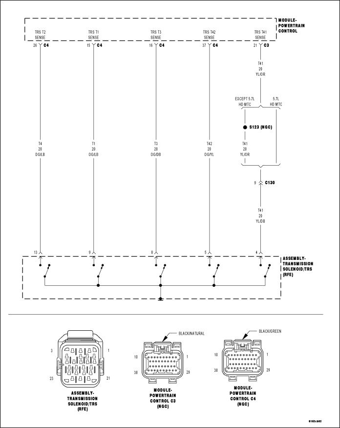
P0706-TRANSMISSION RANGE SENSOR RATIONALITY
For a complete wiring diagram Refer to Section 8W.
DR AUTOMATIC TRANSMISSION - 545RFE - ELECT
• When Monitored:
Continuously with the ignition on.
• Set Condition:
The DTC will set if the controller detects an invalid PRNDL code which lasts for more than 0.042 seconds.
Possible Causes
SHIFTER OUT OF ADJUSTMENT
TRS SENSE CIRCUIT OPEN
TRS SENSE CIRCUIT SHORT TO GROUND
TRS SENSE CIRCUIT SHORT TO VOLTAGE
METAL DEBRIS IN OIL PAN
TRANSMISSION RANGE SENSOR
POWERTRAIN CONTROL MODULE
Always perform the 45RFE/545RFE Pre-Diagnostic Troubleshooting Procedure before proceeding. (Refer to 21 - TRANSMISSION/TRANSAXLE/AUTOMATIC - 45RFE/545RFE - STANDARD PROCEDURE)
Theory of Operation
The T1, T2, T3, T41, or T42 (C1 - C5) Sense circuits communicate the shift lever position to the Transmission Control System. Each circuit is terminated at the transmission by a switch (TRS). Each switch can be either open or closed, depending on the shift lever position. The PCM can decode this information and determine the shift lever position.
Each shift lever position has it own unique combination of closed and open switches. This is called a PRNDL code. There are 5 switches, therefore: there are many possible combinations of open and closed switches (codes). There are 12 valid codes: two for neutral, one for each other gear position (5), and five temporary (transition zone) codes. The remainder of the codes should never occur, these are called invalid codes.
Diagnostic Test
1. CHECK TO SEE IF P0706 DTC IS CURRENT
With the scan tool, perform the Shift Lever Position Test.
Select the test outcome from the following:
Test passes:
Go To 6
Test fails with Error Code:
Go To 2
Test fails without Error Code:
Perform the Gearshift Adjustment Procedure per the Service Information.
Perform 45RFE/545RFE TRANSMISSION VERIFICATION TEST - VER 1. (Refer to 21 - TRANSMISSION/TRANSAXLE/AUTOMATIC - 45RFE/545RFE - STANDARD PROCEDURE)
2. CHECK THE TRANSMISSION SOLENOID/TRS ASSEMBLY
Turn the ignition off to the lock position.
Remove the Ignition Switch Feed fuse from the TIPM.
CAUTION: Removal of the Ignition Switch Feed fuse from the TIPM will prevent the vehicle from being started in gear.
WARNING: The Ignition Switch Feed fuse must be removed from the TIPM. Failure to do so can result in personal injury or death.
Install Transmission Simulator, Miller tool #8333. Ignition on, engine not running.
With the scan tool, perform the Shift Lever Position Test.

21 - 600 AUTOMATIC TRANSMISSION - 545RFE - ELECTRIDR
When the scan tool instructs you to put the Gear Selector in a particular position, you must do so using the selector switch on the Transmission Simulator.
The LED for the gear position in question must be illuminated on the Transmission Simulator prior to pressing 9ENTER9 on the scan tool.
NOTE: When the scan tool requests the O/D off button be depressed, you must use the O/D OFF button in the vehicle or you will fail the Shift Lever Position Test with an error code 11 or OD-TOW/HALL STUCK OPEN.
NOTE: If the Shift Lever Position test fails, make sure to note the identification of the TRS Sense circuit for future reference.
Did the Shift Lever Position test pass?
Yes >> Remove the Oil Pan and Main Valve Body Assembly per the Service Information. Check for metal debris on top of the Solenoid/TRS Assembly and the manual valve code plate. If debris is present, determine the cause of the debris and repair the transmission as necessary. If no problems are found, replace the Transmission Solenoid/TRS Assembly per the Service Information.
Perform 45RFE/545RFE TRANSMISSION VERIFICATION TEST - VER 1. (Refer to 21 - TRANSMISSION/TRANSAXLE/AUTOMATIC - 45RFE/545RFE - STANDARD PROCEDURE)
No >> Go To 3
3. TRS SENSE CIRCUIT OPEN
Turn the ignition off to the lock position.
Disconnect the Transmission Simulator, Miller tool #8333.
Disconnect the PCM harness connectors and install Miller tool #8815.
CAUTION: Do not probe the PCM harness connectors. Probing the PCM harness connectors will damage the PCM terminals resulting in poor terminal to pin connection. Install Miller tool #8815 to perform diagnosis.
Measure the resistance of the identified (T1, T2, T3, T41, or T42) TRS Sense circuit, from the Transmission Solenoid/TRS Assembly harness connector to the appropriate terminal of Miller tool #8815.
Is the resistance above 5.0 ohms?
Yes >> Repair the identified (T1, T2, T3, T41, or T42) TRS Sense circuit for an open.
Perform 45RFE/545RFE TRANSMISSION VERIFICATION TEST - VER 1.
No >> Go To 4
4. TRS SENSE CIRCUIT SHORT TO GROUND
Measure the resistance between ground and the identified (T1, T2, T3, T41, or T42) TRS Sense circuit.
Is the resistance below 5.0 ohms?
Yes >> Repair the identified (T1, T2, T3, T41, or T42) TRS Sense circuit for a short to ground.
Perform 45RFE/545RFE TRANSMISSION VERIFICATION TEST - VER 1. (Refer to 21 - TRANSMISSION/TRANSAXLE/AUTOMATIC - 45RFE/545RFE - STANDARD PROCEDURE)
No >> Go To 5

DR AUTOMATIC TRANSMISSION - 545RFE - ELECT
5. TRS SENSE CIRCUIT SHORT TO OTHER CIRCUITS
Measure the resistance between the identified (T1, T2, T3, T41, or T42) TRS Sense circuit and all other circuits in the Transmission Solenoid/TRS Assembly harness connector.
Is the resistance below 100k ohms between the identified (T1, T2, T3, T41, or T42) TRS Sense circuit and any other circuit(s) in the Transmission Solenoid/TRS Assembly harness connector?
Yes >> Repair the identified (T1, T2, T3, T41, or T42) TRS Sense circuit for a short to other circuit(s). Perform 45RFE/545RFE TRANSMISSION VERIFICATION TEST - VER 1. (Refer to 21 - TRANSMISSION/TRANSAXLE/AUTOMATIC - 45RFE/545RFE - STANDARD PROCEDURE)
No >> Using the schematics as a guide, check the Powertrain Control Module (PCM) terminals for corrosion, damage, or terminal push out. Pay particular attention to all power and ground circuits. If no problems are found, replace the PCM per the Service Information. With the scan tool, perform QUICK LEARN. Perform 45RFE/545RFE TRANSMISSION VERIFICATION TEST - VER 1. (Refer to 21 - TRANSMISSION/TRANSAXLE/AUTOMATIC - 45RFE/545RFE - STANDARD PROCEDURE)
6. INTERMITTENT WIRING AND CONNECTORS
The conditions necessary to set the DTC are not present at this time.
Using the schematics as a guide, inspect the wiring and connectors specific to this circuit. Wiggle the wiring and connectors while checking for shorted and open circuits.
With the scan tool, check the DTC EVENT DATA to help identify the conditions in which the DTC was set.
Were there any problems found?
Yes >> Repair as necessary.
Perform 45RFE/545RFE TRANSMISSION VERIFICATION TEST - VER 1. (Refer to 21 - TRANSMISSION/TRANSAXLE/AUTOMATIC - 45RFE/545RFE - STANDARD PROCEDURE)
No >> Test Complete.

21 - 602 AUTOMATIC TRANSMISSION - 545RFE - ELECTRIDR
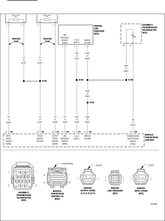
P0711-TRANSMISSION TEMPERATURE SENSOR PERFORMANCE
For a complete wiring diagram Refer to Section 8W.

DR AUTOMATIC TRANSMISSION - 545RFE - ELECT
• When Monitored:
Continuously with the ignition on and engine running.
• Set Condition:
This DTC will set when the desired transmission temperature does not reach a normal operating temperature within a given time frame. Time is variable due to ambient temperature. Approximate times are starting temperature to warm up time: (-40° F / -40° C - 35 min) (-20° F / -28° C - 25 min) (20° F / -6.6° C - 20 min) (60° F / 15.5 ° C - 10 min)
Possible Causes
RELATED DTC’S PRESENT
TRANSMISSION TEMPERATURE SENSOR
POWERTRAIN CONTROL MODULE
Always perform the 45RFE/545RFE Pre-Diagnostic Troubleshooting Procedure before proceeding. (Refer to 21 - TRANSMISSION/TRANSAXLE/AUTOMATIC - 45RFE/545RFE - STANDARD PROCEDURE)
Theory of Operation
The Transmission Temperature Sensor is a variable resistor that changes with temperature, or otherwise known as a thermister. The temperature of the transmission fluid can affect a variety of electronically controlled transmission operations such as shift quality, torque converter lock-up, and when and/or if certain OBDII or system self-diagnostic test are performed. The Powertrain Control Module (PCM) substitutes a calculated transmission temperature value if a fault is detected in the Transmission Temperature Sensor circuit.
Diagnostic Test
1. DETERMINE IF RELATED DTC’S ARE PRESENT
With the scan tool, check Transmission DTC’s.
Are there any other related Transmission Temperature Sensor DTCs present?
Yes >> Refer to the Transmission category and perform the appropriate symptom.
No >> Go To 2
2. CHECK IF DTC IS CURRENT
With the scan tool, Check the STARTS SINCE SET counter for P0711.
NOTE: This counter only applies to the last DTC set.
Is the STARTS SINCE SET counter 2 or less?
Yes
No
3.
Turn the ignition off to the lock position.
Remove the Ignition Switch Feed fuse from the TIPM.
CAUTION: Removal of the Ignition Switch Feed fuse from the TIPM will prevent the vehicle from being started in gear.
WARNING: The Ignition Switch Feed fuse must be removed from the TIPM. Failure to do so can result in personal injury or death.
Install the Transmission Simulator, Miller tool #8333. Ignition on, engine not running.
With the Transmission Simulator, turn the Input/Output switch to OFF.
With the scan tool, monitor the TRANS TEMP VOLTS while turning the Thermistor Voltage switch to all three positions on the Transmission Simulator.

21 - 604 AUTOMATIC TRANSMISSION - 545RFE - ELECTRIDR
Compare the scan tool readings to the voltage readings listed on the Transmission Simulator.
Do the readings on the scan tool match the Transmission Simulator readings ± 0.2 volts?
Yes >> Replace Transmission Solenoid/TRS Assembly per the Service Information.
Perform 45RFE/545RFE TRANSMISSION VERIFICATION TEST - VER 1. (Refer to 21 - TRANSMISSION/TRANSAXLE/AUTOMATIC - 45RFE/545RFE - STANDARD PROCEDURE)
No >> Using the schematics as a guide, check the Powertrain Control Module (PCM) terminals for corrosion, damage, or terminal push out. Pay particular attention to all power and ground circuits. If no problems are found, replace the PCM per the Service Information. With the scan tool, perform QUICK LEARN. Perform 45RFE/545RFE TRANSMISSION VERIFICATION TEST - VER 1. (Refer to 21 - TRANSMISSION/TRANSAXLE/AUTOMATIC - 45RFE/545RFE - STANDARD PROCEDURE)
4. INTERMITTENT WIRING AND CONNECTORS
The conditions necessary to set this DTC are not present at this time.
Using the schematics as a guide, inspect the wiring and connectors specific to this circuit. Wiggle the wires while checking for shorted and open circuits.
With the scan tool, check the DTC EVENT DATA to help identify the conditions in which the DTC was set.
Were there any problems found?
Yes >> Repair as necessary.
Perform 45RFE/545RFE TRANSMISSION VERIFICATION TEST - VER 1. (Refer to 21 - TRANSMISSION/TRANSAXLE/AUTOMATIC - 45RFE/545RFE - STANDARD PROCEDURE)
No >> Test Complete.
DR AUTOMATIC TRANSMISSION - 545RFE - ELECT
P0712-TRANSMISSION TEMPERATURE SENSOR LOW
For a complete wiring diagram Refer to Section 8W.

•When Monitored: DR
Continuously with the ignition on and engine running.
•Set Condition:
The DTC will set when the monitored Temperature Sensor voltage drops below 0.078 volts for the period of 0.45 seconds.21 LECTRI
Possible Causes
RELATED DTC’S PRESENT
(T54) TRANSMISSION TEMPERATURE SENSOR SIGNAL CIRCUIT SHORT TO GROUND
TRANSMISSION TEMPERATURE SENSOR
POWERTRAIN CONTROL MODULE
Always perform the 45RFE/545RFE Pre-Diagnostic Troubleshooting Procedure before proceeding. (Refer to 21 - TRANSMISSION/TRANSAXLE/AUTOMATIC - 45RFE/545RFE - STANDARD PROCEDURE)
Theory of Operation
The Transmission Temperature Sensor is a variable resistor that changes with temperature, or otherwise known as a thermister. The temperature of the transmission fluid can affect a variety of electronically controlled transmission operations such as shift quality, torque converter lock-up, and when and/or if certain OBDII or system self-diagnostic test are performed. The Powertrain Control Module (PCM) substitutes a calculated transmission temperature value if a fault is detected in the Transmission Temperature Sensor circuit.
Diagnostic Test
1. DETERMINE IF RELATED DTC’S ARE PRESENT
With the scan tool, check Transmission DTC’s.
Are there any line pressure sensor or throttle position sensor DTCs present?
Yes >> Refer to the Transmission category and perform the appropriate symptom.
No >> Go To 2
2. CHECK TO SEE IF DTC IS CURRENT
With the scan tool, Check the STARTS SINCE SET counter for P0712.
NOTE: This counter only applies to the last DTC set.
Is the STARTS SINCE SET counter 2 or less?
Yes
No
3.
Turn the ignition off to the lock position.
Remove the Ignition Switch Feed fuse from the TIPM.
CAUTION: Removal of the Ignition Switch Feed fuse from the TIPM will prevent the vehicle from being started in gear.
WARNING: The Ignition Switch Feed fuse must be removed from the TIPM. Failure to do so can result in personal injury or death.
Install the Transmission Simulator, Miller tool #8333. Ignition on, engine not running.
With the Transmission Simulator, turn the Input/Output switch to OFF.
With the scan tool, monitor the TRANS TEMP VOLTS while turning the Thermistor Voltage switch to all three positions on the Transmission Simulator.

CompareDR the scan tool readings with the numbers listed on the Transmission Simulator.
Do the readings on the Transmission Simulator match the scan tool readings ± 0.2 volts?
Yes >> Replace Transmission Solenoid/TRS Assembly per the Service Information.
Perform 45RFE/545RFE TRANSMISSION VERIFICATION TEST - VER 1. (Refer to 21 - TRANSMISSION/TRANSAXLE/AUTOMATIC - 45RFE/545RFE - STANDARD PROCEDURE)
No >> Go To 4
4. (T54) TRANSMISSION TEMPERATURE SENSOR SIGNAL CIRCUIT SHORT TO GROUND
Turn the ignition off to the lock position.
Disconnect the Transmission Simulator, Miller tool #8333.
Disconnect the PCM C4 harness connector and connect Miller tool #8815.
NOTE: Check connectors - Clean/repair as necessary.
CAUTION: Do not probe the PCM harness connectors. Probing the PCM harness connectors will damage the PCM terminals resulting in poor terminal to pin connection. Install Miller tool #8815 to perform diagnosis.
Measure the resistance between ground and the (T54) Transmission Temperature Sensor Signal circuit.
Is the resistance below 5.0 ohms?
Yes >> Repair the (T54) Transmission Temperature Sensor Signal circuit for a short to ground.
Perform 45RFE/545RFE TRANSMISSION VERIFICATION TEST - VER 1. (Refer to 21 - TRANSMISSION/TRANSAXLE/AUTOMATIC - 45RFE/545RFE - STANDARD PROCEDURE)
No >> Using the schematics as a guide, check the Powertrain Control Module (PCM) terminals for corrosion, damage, or terminal push out. Pay particular attention to all power and ground circuits. If no problems are found, replace the PCM per the Service Information. With the scan tool, perform QUICK LEARN.
Perform 45RFE/545RFE TRANSMISSION VERIFICATION TEST - VER 1. (Refer to 21 - TRANSMISSION/TRANSAXLE/AUTOMATIC - 45RFE/545RFE - STANDARD PROCEDURE)
5. INTERMITTENT WIRING AND CONNECTORS
The conditions necessary to set this DTC are not present at this time.
Using the schematics as a guide, inspect the wiring and connectors specific to this circuit. Wiggle the wires while checking for shorted and open circuits.
With the scan tool, check the DTC EVENT DATA to help identify the conditions in which the DTC was set.
Were there any problems found?
Yes >> Repair as necessary.
Perform 45RFE/545RFE TRANSMISSION VERIFICATION TEST - VER 1. (Refer to 21 - TRANSMISSION/TRANSAXLE/AUTOMATIC - 45RFE/545RFE - STANDARD PROCEDURE)
No >> Test Complete.
21 - 608 AUTOMATIC TRANSMISSION - 545RFE - ELECTRIDR
P0713-TRANSMISSION TEMPERATURE SENSOR HIGH
For a complete wiring diagram Refer to Section 8W.
 Loading...