

Page 1
1000Base-T to mini-GBIC
Media Converter
Before Your Begin
This Quick Installation Guide gives step-by-step
instructions for setting up the D-Link DMC-805G
1000Base-T to mini-GBIC Media Converter. The
model you have purchased may appear slightly
different from those shown in the illustrations. For
more detailed information about the media
converter, its components, making network
connections and technical specifications, please
refer to the User’s Manual included with your
media converter.
DMC-805G
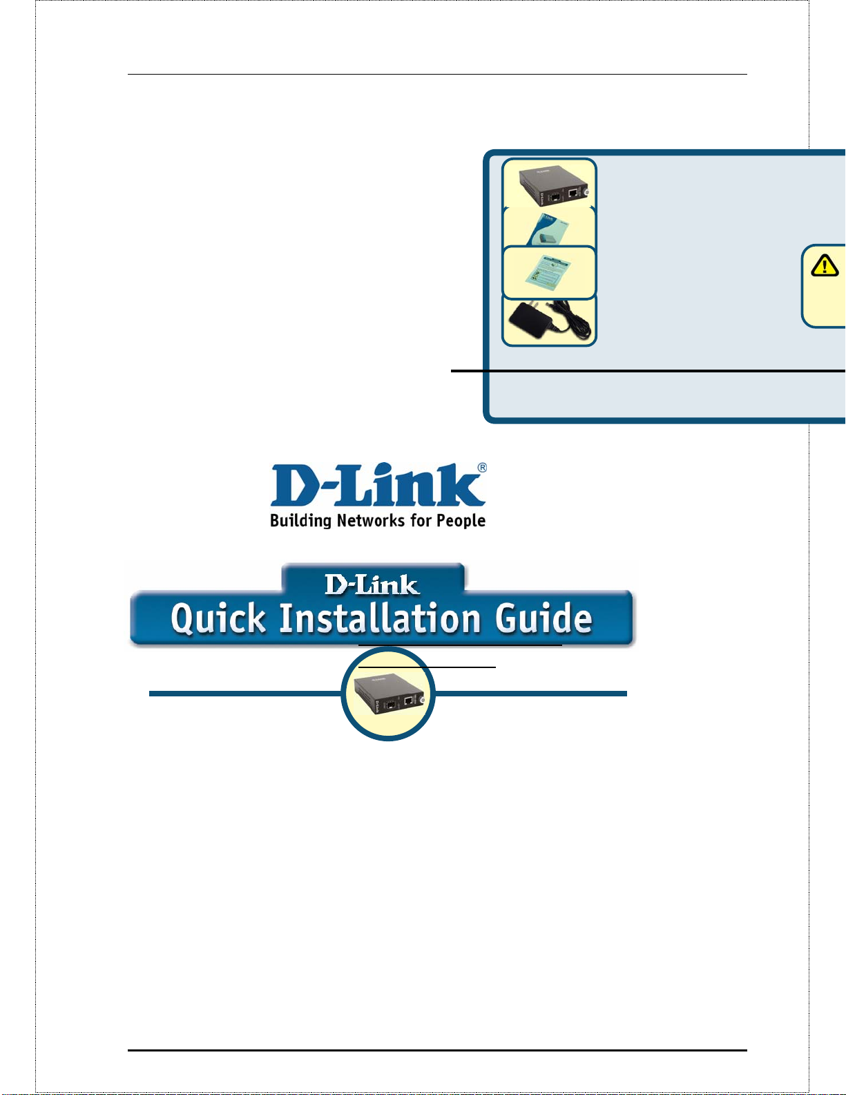
Check Your Package
Contents
These are the items included with your DMC-805G
purchase:
If any of the above items are missing, please contact your
reseller.
©2004 D-Link Systems, Inc. All rights reserved.
Trademarks or registered trademarks are the property
of their respective holders. Software and
specifications subject to change without notice.
• DMC-805G 1000Base-T to mini-GBIC Media
Converter
•User Manual
• Quick Installation Guide
•7.5V DC, 1.5A Power Adapter
Using a power
supply with a different
voltage rating will damage
and void the warranty for
Page 2
2
Setup The DMC-805G
Single Fiber Media
Converter
As with any electric device, you should
place the equipment where it will not
be subjected to extreme temperatures,
humidity, or electromagnetic
interference. Specifically, the site you
select should meet the following
requirements:
A. The ambient temperature should be
between 32 and 104 degrees
Fahrenheit (0 to 40 degrees Celsius).
B. The relative humidity should be less
than 90 percent, non-condensing.
C. Surrounding electrical devices should
not exceed the electromagnetic field
(RFC) standards for IEC 801-3, Level
2 (3V/M) field strength.
D. Make sure that the equipment receives
adequate ventilation. Do not block the
ventilation holes on each side of the
media converter or the fan exhaust
port on the side or rear of the
equipment.
E. The power outlet should be within 1.8
meters of the switch.
Connecting the power
1
2
12
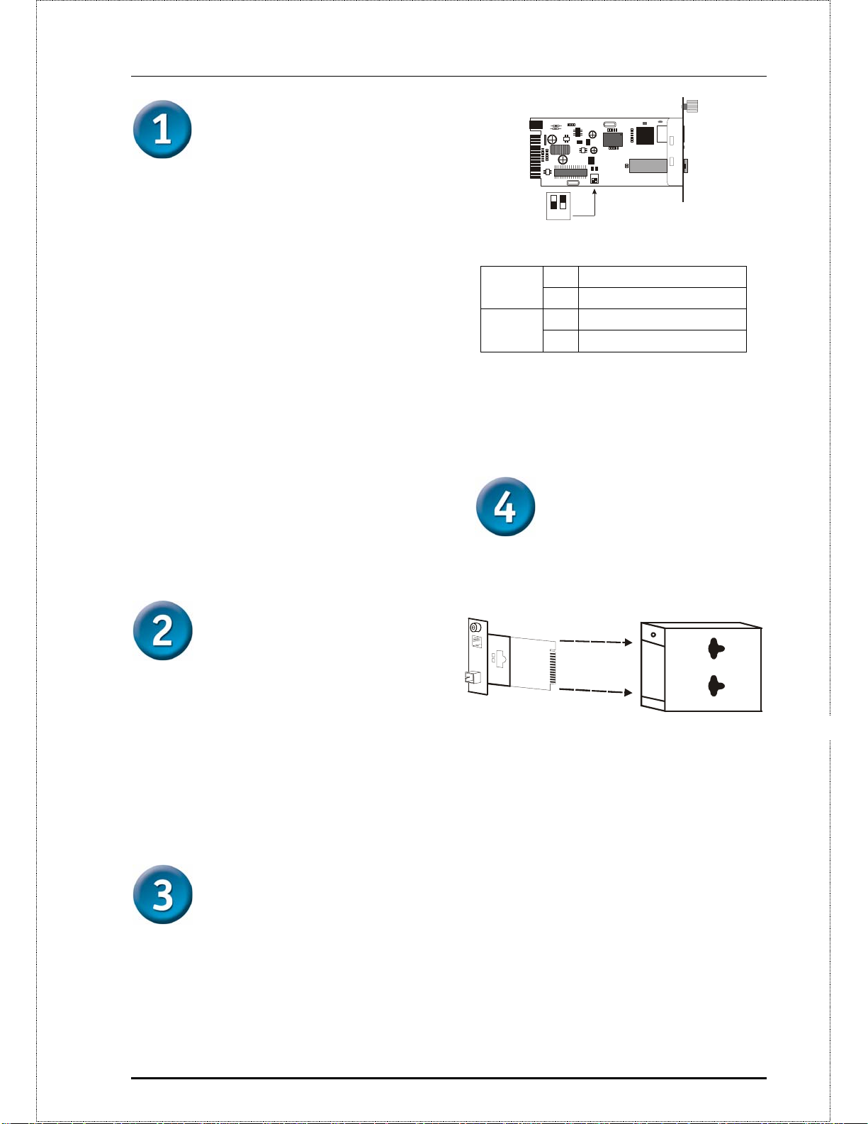
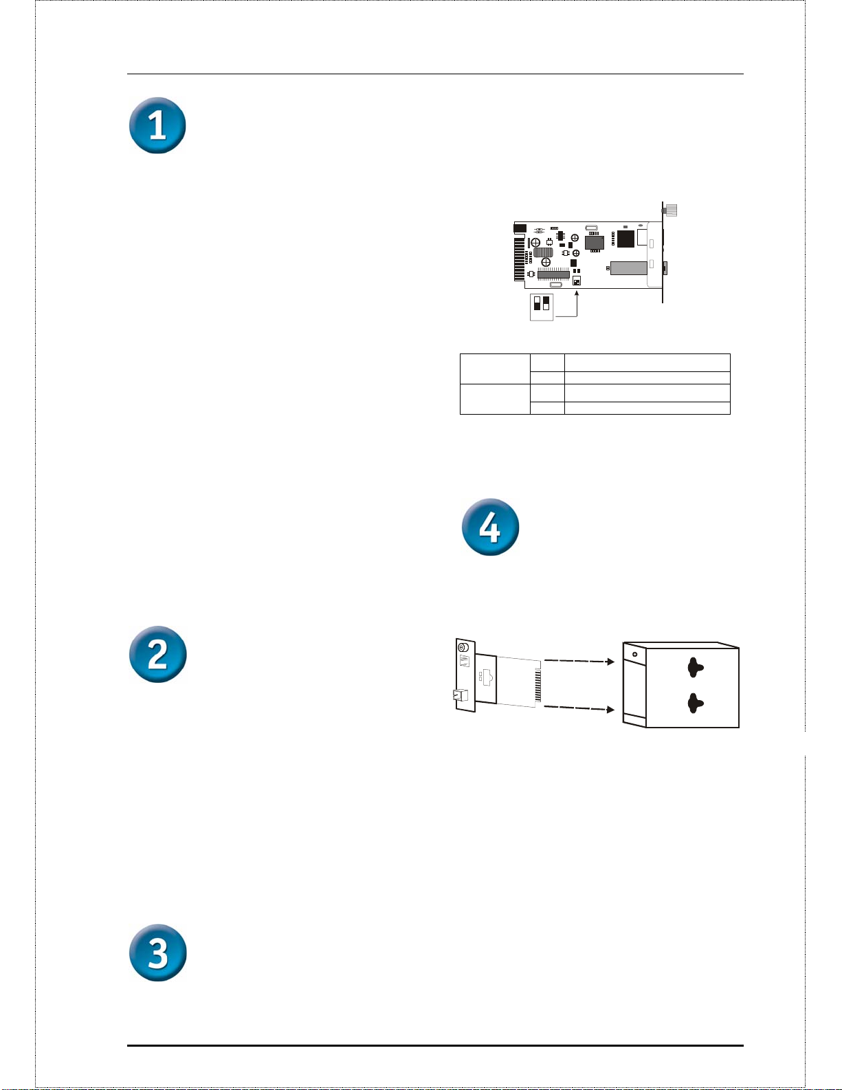
Switch 1 : On -> Forced Mode
Off -> Au to Negot iat ion mode
Switch 2 : On -> LLR enable
Switch 1
Switch 2
Off -> LLR disable
On Fiber Forced Mode
Off Fiber Auto-Negotiation
On LLR Enable
Off LLR Disable
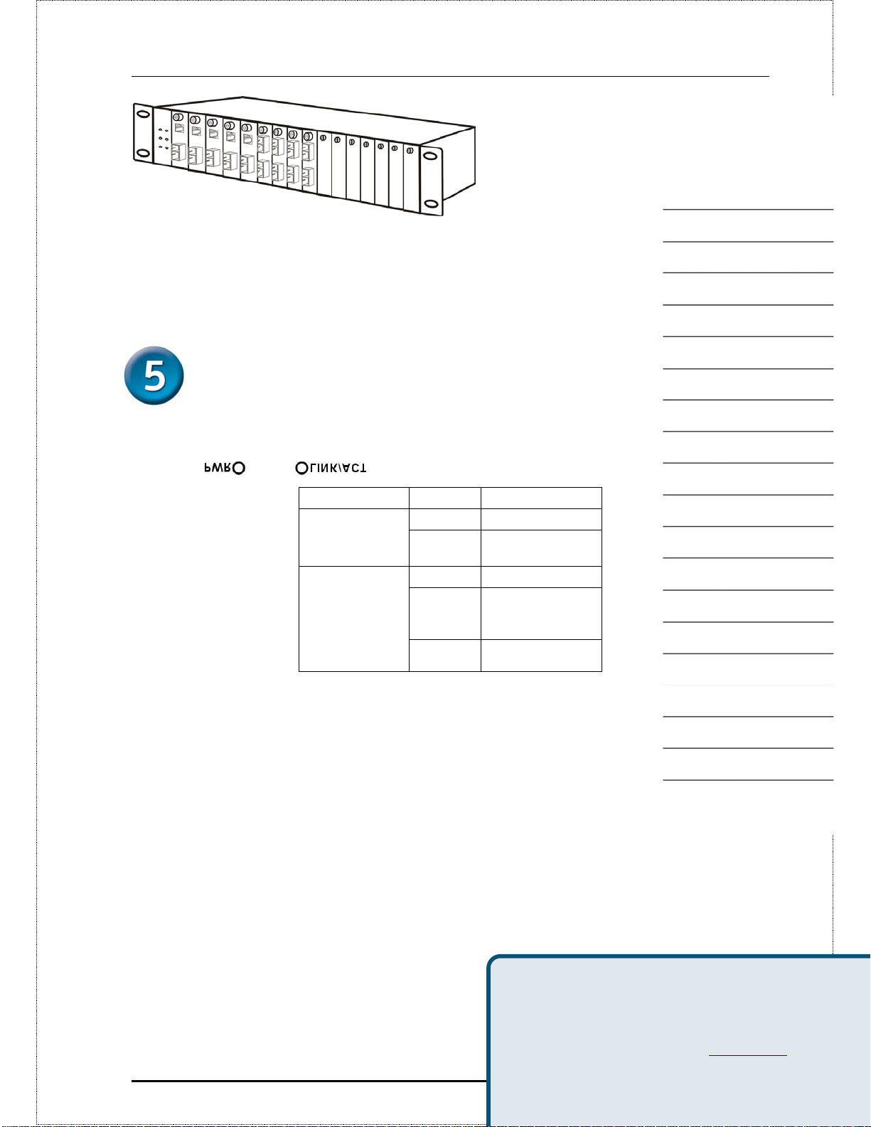
Installing in a
Chassis
The Converter can be fit into any
of the expansion slots on a special
designed chassis.
1. This Converter is a plug-and-play
device.
2. Connect the supplied AC to DC
power adaptor with a power
voltage of 7.5Vdc/1.5Amp to the
receptacle on the rear panel of the
converter, and then attach the plug
into a standard AC outlet with a
voltage range from 100 to 260
Vac.
Sliding Switch
There is a sliding switch for duplex mode
setting for fiber port. Refer to the table
below for more details.
Unscrew and pull out the media converter board
y First, install the converter onto a carrier
supplied with the chassis:
Step 1- Unscrew the carrier from the
desired expansion slot on the chassis.
Step 2- Remove the screw on the
converter as shown below.
Step 3- Fit the converter onto the
carrier and use the screw to secure it.
Page 3

3
n
t
c
t
LED Indicators
The LED indicators give you
instant feedback on status of the
converter:
LEDs State Indication
Power
(PWR)
Lights on Power on
Lights off Power off
Link and
Activity
(LINK/ACT)
Lights on Linking
Lights
Blinking
Data transmitting and
receiving
Lights off Not Linking
You can find software updates and user documentation on the D-Li
D-Link provides free technical support for customers within the Uni
within Canada for the duration of the warranty period on this produ
U.S. and Canadian customers can contact D-Link technical suppor
Technical Support
website, or by phone.
Tech Support for customers within t
States:
D-Link Technical Support over the Telephone:
Page 4
w
t
n
g
m
s
Sollten eine oder mehrere der oben aufgeführten
Positionen fehlen, kontaktieren Sie bitte Ihren Händler.
©2004 D-Link Systems, Inc. Alle Rechte vorbehalten. Warenzeichen
oder eingetragene Warenzeichen sind Eigentum der entsprechenden
Inhaber. Änderungen an Software und Spezifikationen vorbehalten.
Hin
Netzadap
Nennspa
Beschädi
sowie zu
Gantiean
DMC-805G
1000Base-T to mini-GBIC
Media Converter
Voraussetzungen
Dieser Quick Installation Guide enthält eine
schrittweise Anleitung zur Einrichtung des D-Link
DMC-805G 1000Base-T to mini-GBIC Media
Converter. Das von Ihnen erworbene Modell kann
von der Abbildung leicht abweichen. Weitere
Informationen zum DMC-805G, zu den
Komponenten, technischen Spezifikationen und zum
Aufbau von Netzwerkverbindungen entnehmen Sie
dem mit dem Media Converter ausgelieferten
Handbuch.
Prüfen des Paketinhalts
Mit dem Kauf des DMC-805G erhalten Sie
folgendes Zubehör:
• DMC-805G 1000BASE-T to mini-GBIC Media
Converter
• Benutzerhandbuch
4
Page 5
5
d
Einrichtung des
DMC-805G Media
Converters
Wie jedes elektrische Gerät darf der
DMC-805G keinen
Extremtemperaturen, Feuchtigkeit
oder elektromagnetischen Störfeldern
ausgesetzt werden. Bei der
Standortwahl sind v.a. folgende
Voraussetzungen zu beachten:
A. Die Umgebungstemperatur sollte
zwischen 0 bis 40 Grad Celsius
betragen.
B. Die relative Feuchtigkeit sollte unter
90% (nicht kondensierend) betragen.
C. In der Umgebung aufgestellte
elektrische Geräte dürfen die
Feldstärkewerte gemäß der RFC-
Standards für IEC 801-3, Level 2
(3V/M) nicht überschreiten.
D. Stellen Sie sicher, dass die Einrichtung
ausreichend belüftet wird. Die
Lüftungslöcher an den Seiten des
Geräts und die Lüfteröffnungen an der
Seite bzw. auf der Rückseite des
Media Converters dürfen in keinem
Fall blockiert werden.
E. Die Entfernung zur nächsten
Stromquelle sollte max. 1,8 Meter
betragen.
Schalter 1:
Schalter 2:
Die Duplexbetrieb-Einstellung für den
Fiber Port erfolgt über einen
Gleitschalter. Weitere Einzelheiten
entnehmen Sie der Tabelle weiter
unten.
1
2
12
Switch 1 : On -> Forced Mode
Off -> Au to Negot iat ion mode
Switch 2 : On -> LLR enable
Off -> LLR disable
An Glasfaser Standardmodus
Aus Glasfaser Auto-Negotiation
An LLR aktiviert
Aus LLR deaktiviert
Gehäuseinstallation
Der Converter lässt sich im
Erweiterungsslot eines Spezialgehäuses
installieren.
Anschließen an die
Stromversorgung
1. Der Converter ist Plug-and-Playfähig.
2. Verbinden Sie das mitgelieferte
AC/DC-Netzadapter
(7,5VDC/1,5Amp) mit dem
Anschluss auf der Rückseite des
Converters und. Schließen Sie
den Stecker des Netzadapters
danach an eine ACStandardsteckdose (Spannung
von 100 -260 VAC) an.
Gleitschalter
Lösen Sie die Schrauben des Media Converters und ziehen Sie das Boar
y Installieren Sie den Converter zuerst in
der mit dem Gehäuse ausgelieferten
Trägervorrichtung:
Schritt 1 - Lösen Sie den Träger
vom entsprechenden Erweiterungsslot
des Gehäuses.
Schritt 2 - Entfernen Sie die
Schraube des Konverters wie unten
dargestellt.
Schritt 3 - Befestigen Sie den
Converter mit der Schraube an der
Trägervorrichtung.
Page 6
e
r
LED-Anzeigen
Anhand der LED-Anzeigen ist
Converter-Status jederzeit ablesbar:
LEDs Status Bedeutung
(PWR)
LINK/ACT
An Eingeschaltet Stromversorgung
Aus Ausgeschaltet
An Verbunden
Datenübertragung
Blinkend
oder
Datenempfang
Aus Nicht verbunden
Technischer Support
Aktualisierte Versionen von Software und Benutzerhandbuch
auf der Website von D-Link unter www.dlink.de
.
D-Link bietet kostenfreie technische Unterstützung für Kund
6
Deutschlands, Österreichs, der Schweiz und Osteuropas.
Unsere Kunden können technische Unterstützung über unse
Page 7
7
r
5
A
L
u
n
m
a
Convertisseur de média monofibre
1000BASE-T/mini-GBIC
Vérifiez le contenu de l’emballage
Voici les éléments que doit contenir l’emballage du
DMC-805G :
Si l’un des éléments ci-dessus manque, contactez votre
©2004 D-Link Systems, Inc. Tous droits réservés. Les marques sont la
propriété de leurs propriétaires respectifs. Le logiciel et les spécifications
sont susceptibles d’être modifiés sans préavis.
• Convertisseur de média monofib
1000BASE-T/mini-GBIC DMC-80
• Manuel utilisateur
• Guide d’installation rapide
revendeur.
• Adaptateur secteur 7.5V DC, 1.5
de la te
endom
annuler
-
Avant de commencer
Ce guide d’installation rapide indique étape par
étape comment configurer le convertisseur de
média double longueur d’onde monofibre
1000BASE-T/
mini-GBIC DMC-805G D-Link. Le modèle que
vous avez acheté peut vous sembler
légèrement différent de ceux des illustrations.
Pour plus d’information détaillée sur le
convertisseur de médias, ses composants,
faire des raccordements de réseau et des
caractéristiques techniques, reportez-vous s’il
vous plait au Manuel de l'Utilisateur inclus
avec votre convertisseur de médias.
Page 8

Configuration du
convertisseur de
média monofibre DMC-805G
Comme tout appareil électrique, le
convertisseur de média doit être placé
à un endroit où il ne sera pas soumis à
des températures ou des humidités
extrêmes ou encore à des
perturbations électromagnétiques.
Plus précisément, l’emplacement
choisi doit remplir les conditions
suivantes :
A. La température ambiante doit être
comprise entre 0 et 40°C.
B. L’humidité relative doit être
inférieure à 90% (sans
condensation).
C. Les appareils électriques voisins
ne doivent pas dépasser les
normes de rayonnement
électromagnétique CEI-801-3,
niveau 2 (3 V/m).
D. Assurez-vous que l'équipement
reçoit une ventilation adéquate.
Ne bloquez pas les trous de
ventilation de chaque côté du
convertisseur de médias ou le port
d'échappement de ventilateur sur
le côté ou l'arrière de
l'équipement.
E. La prise de courant doit être à une
distance maximale de 1,8 mètre
du convertisseur.
Alimentation
1. Ce convertisseur est un équipement
« plug and play » (il est reconnu
automatiquement par le système
d’exploitation).
2. Branchez l'adaptateur secteur
7,5Vdc/1,5A sur le convertisseur (à
l’arrière) et sur une prise de courant
alternatif normale (100 à 260 V).
Inverseur 1
Inverseur 2
Un commutateur à glissière permet
de sélectionner le mode duplex
pour le port fibre. Reportez-vous au
tableau ci-dessous pour plus de
détails.
1
2
12
Switch 1 : On -> Forced Mode
Off -> Au to Negot iat ion mode
Switch 2 : On -> LLR enable
Off -> LLR disable
On Mode forcé fibre
Off Négociation automatique fibre
On Activation LLR
Off Désactivation LLR
Installation dans un
châssis
Le convertisseur peut être installé
dans n'importe quel emplacement
d’extension d'un châssis spécial.
Dévissez et sortez la carte convertisseur
Commencez par installer le
convertisseur sur un support fourni
avec le châssis :
Étape 1- Dévissez le support de
l’emplacement d’extension désiré.
Étape 2- Retirez la vis du
convertisseur comme indiqué
ci-dessous.
Étape 3- Fixez la carte
convertisseur au support avec la vis.
Configuration
8
Page 9

9
Page 10

0
é
s
Voyants lumineux
Les voyants lumineux indiquent
l’état du convertisseur :
(PWR)
Allumé Alimentation on
Eteint Alimentation off
Allumé Liaison
Clignot
ant
Émission ou réception
de données
Eteint Pas de liaison
LEDs Status Indication
Alimentation
LINK/ACT
Vous trouverez la documentation et les logiciels les plus r
Assistance technique
sur le site web D-Link.
Le service technique de D-Link est gratuit pour les client
1
Etats-Unis durant la période de garantie.
Ceuxci peuvent contacter le service technique de
Page 11

1000BASE-T to mini-GBIC
Antes de empezar
Esta guía de instalación rápida recoge las
instrucciones detalladas para configurar el
conversor de medios D-Link DMC-805G 1000BASE-T
to mini-GBIC. El modelo que se ha adquirido puede
presentar alguna diferencia respecto al que se
muestra en las ilustraciones. Si se desea
información más detallada sobre el conversor de
medios, sus componentes, las conexiones de red y
las especificaciones técnicas, consúltese el Manual
del usuario que se incluye con el conversor de
medios.
Comprobar el contenido del paquete
Estos son los elementos incluidos en el DMC805G:
• DMC-805G 1000BASE-T to mini-GBIC Media
Converter
• Manual del usuario
Si falta alguno de estos componentes, por
favor contacte con su proveedor.
©2004 D-Link Systems, Inc. Reservados
todos los derechos. Las marcas o marcas registradas son propiedad de
los respectivos titulares. El software y las especificaciones pueden ser
modificados sin previo aviso.
distinto voltaje puede ser
perjudicial y anular la
garantía de este producto.
Configurar el
conversor de medios
DMC-805G
Al igual que otro dispositivo eléctrico,
el equipo no debe exponerse a
elevadas temperaturas, humedad o
interferencias electromagnéticas. La
ubicación seleccionada ha de reunir
las siguientes características:
A. La temperatura ambiental debería
ser de 0 ºC a 40 ºC.
B. La humedad relativa debería ser
inferior al 90 %, sin condensación.
DMC-805G
campo electromagnético (RFC)
para nivel 2 (3V/m) de intensidad
de campo IEC 801-3.
D. El equipo debe disponer de la
adecuada ventilación. No se han
de tapar las ranuras de ventilación
que se encuentran a cada lado del
conversor de medios ni el puerto
de salida del ventilador en el
lateral o parte trasera del equipo.
E. La toma de alimentación debería
encontrarse a 1,8 metros del
conmutador.
11
C. Los
dispositivos
eléctricos
cercanos no
deberían
sobrepasar los
estándares de
El uso de una fuente
de alimentación con
Page 12

2
Conectar el alimentador
1. Este conversor es un dispositivo
plug and play.
2. Conectar el adaptador de
alimentación AC a DC con un voltaje
de alimentación de 7,5 VDC/1,5 A
en la conexión del panel trasero del
conversor, y después introducir el
enchufe en una base estándar AC
de un voltaje de 100 a 260 Vac.
Conmutador
deslizante
Hay un conmutador deslizable para
establecer el modo duplex del puerto
de fibra. Para más detalles véase la
tabla siguiente.
yPrimero, instalar el conversor en el
soporte suministrado con la carcasa:
Paso 1- Destornillar el soporte
de un slot de expansión de la carcasa.
Paso 2- Sacar el tornillo del
conversor, como se muestra en la
imagen.
Paso 3- Colocar el conversor
en el soporte y atornillarlo.
Conmutador 1
Conmutador 2
El conversor puede colocarse en
cualquiera de los slots de expansión
de una carcasa de diseño especial
1
2
12
Switch 1 : On -> Forced Mode
Off -> Au to Negot iat ion mode
Switch 2 : On -> LLR enable
Off -> LLR disable
On Fibra modo forzado
Off Fibra autonegociación
On LLR activado
Off LLR desactivado
Instalar en una
carcasa
Indicadores LED
Los indicadores LED señalan el
estado del conversor:
LEDs Estado Indicación
Encendido
(PWR)
LINK/ACT
Luces
encendidas
Luces
apagadas
Luces
encendidas
Intermitente
Encendido
Parado
Con Link
Transtiendo o
recibiendo datos
Destornillar y sacar la placa base del conversor de
medios
1
Page 13

A
a
w
u
e
i
Luces
apagadas
Sin Link
sistencia Técnic
Puede encontrar el software más rec
documentación para el usuario en el sitio
Link. D-Link ofrece asistencia técnica grat
13
clientes dentro de España durante el pe
garantía del producto. Los clientes español
ponerse en contacto con la asistencia técn
Page 14

ncom
Se uno dei componenti dovesse risultare mancante,
contattare il rivenditore
©2004 D-Link Systems, Inc. Tutti i diritti sono riservati. I marchi e i
marchi registrati sono dei rispettivi proprietari. Software e specifiche
soggetti a cambiamenti senza preavviso.
DMC-805G
dan
Media Converter 1000BASE-T
a mini-GBIC
Prima di cominciare
La Guida di Installazione Rapida fornisce le
istruzioni passo - passo per configurare il
Media Converter D-Link DMC-805G da
1000BASE-T a mini-GBIC. Per maggiori
informazioni sul media converter, i suoi
componenti, sulle connessioni di rete e sulle
specifiche tecniche, fare riferimento al
Manuale Utente incluso con il proprio media
converter.
Contenuto del pacchetto
Il dispositivo DMC-805G viene fornito con i
seguenti componenti :
• Media Converter DMC-805G1000BASE-T e
mini-GBIC
• Manuale Utente
14
Page 15

Setup del Media
Converter DMC-805G
Come qualsiasi dispositivo elettrico, è
necessario posizionare il prodotto in
questione dove non siano presente
temperatura elevata, umidità o
interferenze elettromagnetiche. In
particolare, installare il prodotto in un
luogo dove siano rispettati i seguenti
requisiti ambientali:
A. La temperatura ambiente deve essere
compresa tra i 32 e 104 gradi
Fahrenheit (tra 0 e 40 gradi Celsius).
B. L’umidità relativa deve essere meno
del 90 %, non-condensante.
C. Dispositivi elettrici a diffusione non
devono seguire le emissioni
elettromagnetiche (RFC) dello
standard IEC 801-3, Level 2 (3V/M).
D. Assicurarsi che il dispositivo sia in
luogo ben ventilato. Non chiudere le
fessure di ventilazione ai lati del media
converter o le fessure del ventilatore
nel retro del dispositivo.
E. La presa di corrente deve essere ad
almeno 1.8 metri dal dispositivo.
riferimento alla tabella sotto per
maggiori informazioni.
2
1
12
Switch 1 : On -> Forced Mode
Off -> Au to Negot iat ion mode
Switch 2 : On -> LLR enable
Off -> LLR disable
Ponticello 1
Ponticello 2
On Fibra Modalità forza
Off Fibra Negoziazione
On LLR Abilitato
Off LLR Disabilitato
Installazione in
Chassis
Il media converter può essere inserito in
uno slot di espansione di uno speciale
chassis.
Connessione
dell’alimentazione
1. Questo converter è un dispositivo plugand-play.
2. Connettere la spina del trasformatore
AC/DC con voltaggio di 7.5Vdc/1.5Amp
nel connettore alimentazione sul pannello
posteriore del media converter, e poi
connettere l’altro capo ad una presa di
corrente AC con un voltaggio compreso tra
00 e 260 Vac.
Interruttori a scorrimento
Per l’impostazione della modalità duplex
della porta in fibra ottica, utilizzare la
serie in interruttori a scorrimento. Fare
Svitare e togliere la scheda del media converter
y Primo, installare il media converter
nello slot dello chassis:
Fase 1- Togliere la copertura dello slot
desiderato dallo chassis.
Fase 2- Rimuovere le viti dal media
converter come illustrato sotto
Fase 3- Fissare il media converter
nello slot utilizzando le viti a corredo.
15
Page 16

o
d
Indicatori LED
Gli indicatori LED mostrano lo stato
di funzionamento del media
converter:
LED Stato Indicazione
Aliementazione
(PWR)
LINK/ACT
Luce Accesa Acceso
Luce Spenta Spento
Luce Accesa Collegato
Lampeggiante Trasmissione/ricezione dati
Luce Spenta Non Collegato
Supporto tecnico
Le ultime versioni del software e la documentazione aggi
sono disponibili al sito D-Link.
D-Link fornisce un supporto tecnico gratuito ai clienti resi
16
Italiani per tutto il periodo di validità della garanzia del pro
I clienti italiani possono contattare il supporto tecnico D-Li
Page 17

7
и
Если что-либо из перечисленного отсутствует,
обратитесь к вашему поставщику
©2004 D-Link Systems, Inc. All rights reserved. Trademarks or registered trademarks
are the property of their respective holders. Software and specifications subject to
change without notice.
.
другим
DMC-805G
Управляемый медиаконвертор
1000BASE-T на mini-GBIC
Перед тем как начать
Руководство по быстрой установке дает
пошаговые инструкции для установки
медиаконвертора DMC-805G 1000BASE-T на miniGBIC. Модель, которую Вы приобрели может
незначительно отличаться от показанных на
иллюстрациях. За более подробной
информацией о медиаконверторе, его
компонентах, подключении к сети и технических
спецификациях, обратитесь, пожалуйста, к
руководству пользователя, включенному в
комплект поставки.
Проверьте содержимое комплекта
Эти элементы входят в комплект поставки DMC-
805G:
• Медиаконвертор DMC-805G 1000BASE-T
на mini-GBIC
• Руководство пользователя
1
Page 18

Уст а н овка
медиаконвертора
DMC-805G
Как и любое другое электрическое
устройство, Вы должны поместить
оборудование там, где это не будет
подвергнуто высоким температурам,
влажности, или электромагнитным
помехам. Место, которое Вы
выберите, должно удовлетворять
следующим требованиям:
A. Окружающая температура должна
быть между 0° и 40° C.
B. Относительная влажность меньше,
чем 90% , без конденсата.
C. Окружающие электрические
приборы должны соответствовать
стандарту
(электромагнитные поля) и Level 2
(3/VM) (сила электромагнитного поля)
D. Убедитесь, что место, где
установлено устройство имеет
хорошую
вентиляцию. Не блокируйте
вентиляционные отверстия на
каждой
стороне медиаконвертора, или или их
же на задней панели
E. Электрическ ая розетка должна
находиться не ближе 1.8 метра от
медиаконвертора.
IEC 801-3
оборудования.
порта. Ниже приведена таблица с
подробными установками.
Переключатель 1
Переключатель 2
Установка в
2
1
12
Switch 1 : On -> Forced Mode
Off -> Au to Negot iat ion mode
Switch 2 : On -> LLR enable
Off -> LLR disable
Фиксированный режим
On
для оптического порта
Автопереговоры для
Off
оптического порта
On LLR активно
Off LLR отключено
Подключение
питания
1. Данный медиаконвертор является
устройством
2. Подключите адаптер питания 7.5
В/1.5А, входящий в комплект к
разъему питания на задней панели
медиаконвертора, затем включите
его в стандартную электрическую
розетку.
plug-and-play.
Переключатель на
медиаконверторе
На плате медиаконвертора имеется
переключатель для установки
дуплексного режима для оптического
шасси
Медиаконвертор может быть
установлен в слот расширения
специально разработанного шасси.
y Сначала установите медиаконвертор
в шасси:
Шаг 1- Открутите шуруп и снимете
фальш-панель с нужного слота
расширения.
Снимите корпус медиаконвертора
18
Page 19

у
Шаг 2- Удали те шуруп на
медиаконверторе, как показано ниже.
Шаг 3- Установите медиаконвертор
в шасси и закрепите его.
Индикаторы
Индикаторы позволяют
отслеживать состояние
медиаконвертора:
Индикатор Состояние Описание
Питание
(PWR)
LINK/ACT
Горит Питание включено
Не горит Питание выключено
Горит Связь есть
Мигает Передача данных
Не горит Связи нет
Техническая Поддержка
19
Последние версии ПО и документацию можно пол
web-сайте D-Link
Page 20

0
的並使
如以上物件有任何缺失,請與經銷商聯繫。.
©2004版權所有。D-Link與D-
Link商標為友訊科技的商標,其他註冊商標分別隸屬該公司所有。最新規
格以原廠通告為準,恕不另行通知.
使用
壓
1000BASE-T 到mini-GBIC
開始前
本快速安裝手冊爲安裝D-Link DMC-805G
1000BASE-T轉miniGBIC介質轉換器提供步驟性指導.您購買的産品可
能與插圖中所示的産品稍微不一樣.想獲取關於此介
質轉換器的部件,網路連接,和技術規格的詳細資訊,
請閱所附的使用手冊。
檢查包裝內容
用戶購買的 DMC-805G應包括以下部件:
• DMC-805G 1000BASE-T 到 mini-
DMC-805G
2
GBIC介質轉換器
Page 21

安裝DMC-805G
光纖介質轉換器
1
2
對於任何一台電器設備,您都應將該設備放
在不受較高溫度,潮濕,或電磁影響的地方.
特別是選擇的地方應符合以下要求:
A.周圍的溫度應在華氏溫度32 和 104
度之間, (攝氏0 到 40度).
B.相對濕度應低於百分之九十,非凝結.
C..周圍的電器設備不應超過IEC 8013, 2
(3V/M)磁場強度等級的電磁場(RFC)標準.
D. 保證設備通風良好.
不要阻塞介質轉換器每邊的通風孔或一邊
的風扇排氣口,或設備背面上的風扇排氣
口,
E.電源插座應在交換器1.8米內.
連接電源
Switch 1
Switch 2
12
Switch 1 : On -> Forced Mode
Off -> Au to Negot iat ion mode
Switch 2 : On -> LLR enable
Off -> LLR disable
On Fiber Forced Mode
Off Fiber Auto-Negotiation
On LLR Enable
Off LLR Disable
1. 該轉換器是即插即用設備.
2. 將7.5Vdc/1.5Amp電源電壓的AC到DC電
源供應器連接到轉換器後面板的插座上.
然後再把插頭插進100 t到260
Vac電壓範圍內的標準AC插座中.
滑動式開關
光纖埠具備有滑動式開關可用於設定半/全雙
工模式。詳細資訊請參看下列圖表.
21
Page 22

2
安裝在機箱中
LED指示燈 狀態 表示
電源
(PWR)
LINK/ACT
亮
滅
亮
閃爍
滅
電源供應中
停止運作
連線中
沒有連線
此轉換器可以安裝在經過特別設計的機箱上
的任何一個擴充槽中.
旋出螺絲,拔出介質轉換器檔板
y首先,將該轉換器安裝在由機箱所提供的架
座上:
傳輸或接收資料
LED指示燈
LED指示燈即時爲用戶提供關於轉換器狀態的回饋
資訊:
步驟 1-
從機箱上欲安裝的擴充槽處旋開架座的螺絲
步驟2-按圖所示旋下轉換器上的螺絲
步驟 3將轉換器安裝在架座上,使用螺絲將其固定.
2
Page 23

友冠技術支援
台灣地區用戶可以透過我們的網站,電子郵件或
電話與友冠資訊技術支援人員 聯絡。
支援服務時間從週一到週五,上午8:30 a.m. 到
23
5:30 p.m
 Loading...