

Page 1

Quick Install Guide
1000Base-T to 1000Base-SX/LX
Media Converter
Connecting to Power
1
This Converter is a plug-and-play device.
Connect the supplied AC to DC power adaptor with a
power voltage of 7.5Vdc/1.5Amp to the DC-Jack on the
converter, and then attach the plug into a standard AC outlet.
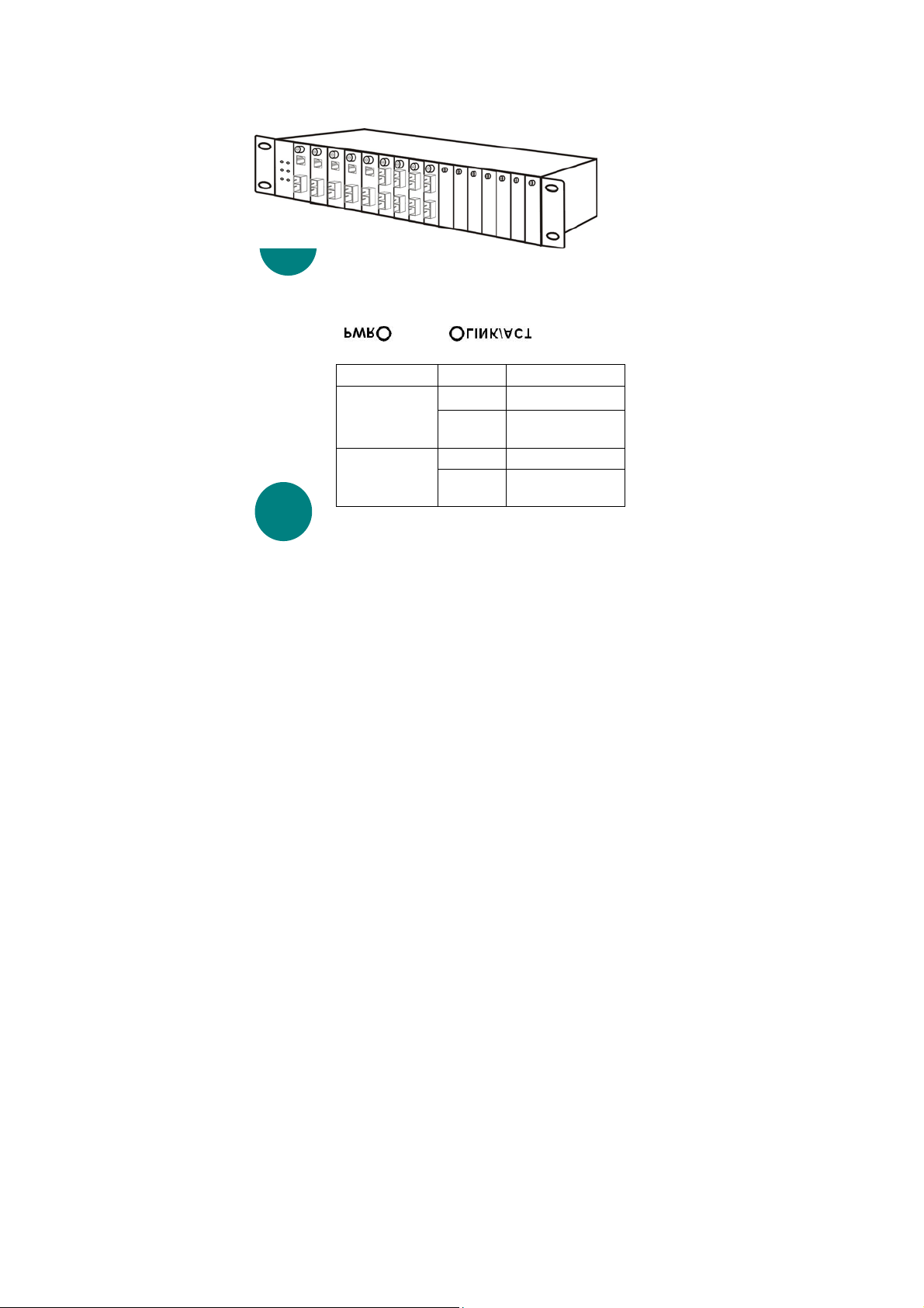
Installing in a Chassis
2
The Converter can be fit into any of the expansion slots on a special
designed chassis.
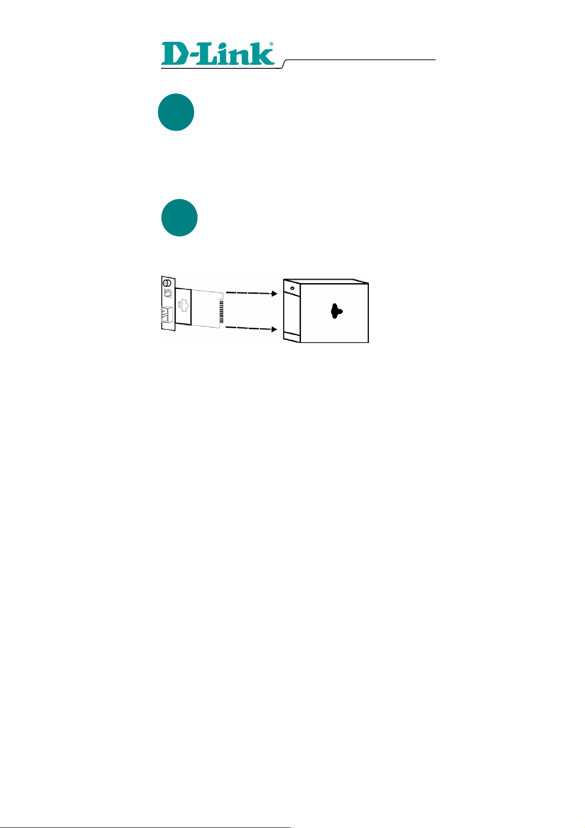
Unscrew and pull out the media converter board
y First, install the converter onto a carrier supplied with the chassis:
Step 1- Unscrew and pull out the media converter board.
Step 2- Plug in the media board to any of the vacant slot.
Step 3- Fit the converter onto the carrier and use the screw to secure it.
1
Page 2

LED Indicator
3
LEDs State Indication
Steady Power on Power
(PWR)
LINK/ACT
Lights off Power off
Lights on Linking
Lights off Not Linking
Link Pass Through Function
4
LLCF (Link Loss Carry Forward)
When a device connected to the converter and the TP line loss the link,
the converter’s fiber will disconnect the link of transmit, so that the
other ends will know that there is a linkage error on this end. And when
the Fiber line loss the link, the converter’s TP will disconnected, and the
other end will know that there is linkage problem exist.
There is a default LLCF setting on this converter.
LLR (Link Loss Return)
When a device connected to the converter and the fiber line loss the link,
the converter’s fiber will disconnect the link of transmit.
There is a switch to enable or disable the function of the media
converter.
2
Page 3

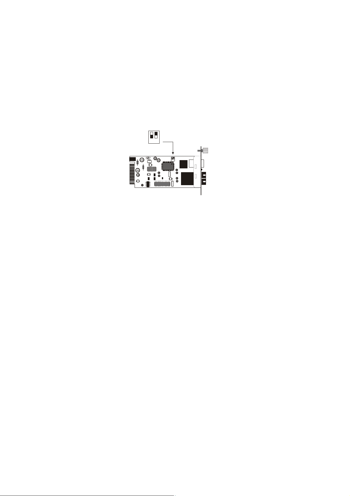
Switch 1 : On -> Forced Mode
Of f - > Au to N ego ti ati on m ode
Switch 2 : On -> LLR enable
Of f -> LL R dis ab le
12
12
Switch
There is a two pin DIP switch on the module which define as switch 1
and switch 2:
Switch 1: Fiber mode switch
When the switch was turned to “On”, it means that the fiber was turned
to forced mode, and “Off” for auto-negotiation mode.
Note: Be sure the opposite end is using the same setting(forced or Autonegotiation). And when using two converters at the same time, the two
converters MUST set to forced mode.
Switch 2: LLR
When the switch was turned to “On”, it means that the LLR was
enabled and “Off” for disabled.
Note: When using two converters at the same time, then only one
converter need to enable the LLR function.
The Switch can be mounted in an EIA standard size, 19-inch rack,
which can be placed in a wiring closet with other equipment. To install,
attach the mounting brackets on the switch’s front panel (one on each
side) and secure them with the screws provided.
3
Page 4
Quick Install Guide
1000Base-T to 1000Base-SX/LX
Media Converter
1
Installation in einem Basisgehäuse
Der Konverter kann in einen beliebigen Erweiterungssteckplatz eines
speziellen Basisgehäuses montiert werden.
Stromversorgung
Dieser Konverter ist ein Plug & Play-Gerät.
Schließen Sie das mitgelieferte Netzteil (7,5 V
Gleichspannung/1,5 A) an die Eingangsbuchse des
Konverters an. Verbinden Sie das Netzteil dann mit einer
Steckdose.
2
Lösen Sie die Schrauben der Medienkonverterkarte und ziehen Sie die Karte heraus.
y Installieren Sie den Konverter zunächst auf einem zum Basisgehäuse
gehörenden Träger. Gehen Sie dabei wie folgt vor:
Schritt 1: Lösen Sie die Schrauben der Medienkonverterkarte und ziehen
Sie die Karte heraus.
Schritt 2: Stecken Sie die Konverterkarte in einen beliebigen freien
Steckplatz.
4
Page 5
Schritt 3: Bringen Sie den Konverter auf dem Träger an. Sichern Sie ihn
mit der Schraube.
3
LED-Anzeigen
4
LEDs Status Bedeutung
Stromversorgung
(PWR)
LINK/ACT
Dauerlicht Eingeschaltet
Aus Ausgeschaltet
An Verbunden
Aus Nicht verbunden
Pass-Through-Funktion
LLCF (Link Loss Carry Forward)
Wenn ein mit dem Konverter und der TP-Leitung verbundenes Gerät
die Verbindung nicht halten kann, wird die Übertragungsverbindung
durch die Glasfaserleitung des Konverters abgebrochen. Dies dient der
anderen Seite als Mitteilung über den Übertragungsfehler. Wenn die
Verbindung von der Glasfaserleitung nicht gehalten werden kann, so
5
Page 6
wird die TP-Leitung des Konverters unterbrochen. Dadurch erhält die
andere Seite Kenntnis von dem aufgetretenen Übertragungsproblem.
Der Konverter ist standardmäßig auf LLCF eingestellt.
LLR (Link Loss Return)
Wenn ein mit dem Konverter und dem Glasfaserleitung verbundenes
Gerät die Verbindung nicht halten kann, wird die
Übertragungsverbindung durch die Glasfaserleitung des Konverters
unterbrochen.
Es ist ein Schalter zum Ein- und Ausschalten der Funktion des
Medienkonverters vorhanden.
Switch 1 : On -> Forced Mode
O ff - > Auto N egoti at ion m ode
Switch 2 : On -> LLR enable
Off -> L LR di sab le
12
12
Schalter
Am Modul befindet sich ein zweiteiliger DIP-Schalter, bezeichnet als
Schalter 1 (Switch 1) und Schalter 2 (Switch 2):
Schalter 1: Schalter für den Modus des Glasfaserkabels
Wenn der Schalter auf „Ein“ gestellt ist, ist das Glasfaserkabel auf den
Standardmodus eingestellt, bei „Aus“ auf den automatischen
Einstellungsmodus.
Hinweis: Stellen Sie sicher, dass die andere Seite dieselben
Einstellungen benutzt (Standardeinstellung oder automatische
Einstellung). Sollten Sie zur gleichen Zeit zwei Konverter in Betrieb
haben, so stellen Sie sicher, dass bei den Konvertern die
Standardeinstellung eingestellt ist.
6
Page 7

Schalter 2: LLR
Wenn der Schalter auf „Ein“ gestellt ist, ist LLR aktiviert, bei „Aus“
deaktiviert.
Hinweis: Sollten Sie zwei Konverter gleichzeitig in Betrieb haben, muss
lediglich bei einem Konverter die LLR-Fuktion aktiviert sein.
7
Page 8

Quick Install Guide
1000Base-T to 1000Base-SX/LX
Media Converter
Alimentation
1
Ce convertisseur est un équipement « plug and play ».
Branchez l'adaptateur d'alimentation secteur conçu pour
fournir 7,5Vdc/1,5A sur le convertisseur et sur une prise
secteur standard.
2
Installation dans un châssis
Le convertisseur peut être installé dans n'importe quel emplacement
d’extension d'un châssis spécial.
Dévissez et tirez le convertisseur
y Commencez par installer le convertisseur sur un support fourni avec le
châssis :
Étape 1- Dévissez et tirez le convertisseur.
Étape 2- Enfichez le convertisseur dans l'un des emplacements vides.
Étape 3- Fixez le convertisseur sur le support à l'aide d'une vis.
8
Page 9

Voyants
3
LEDs Status Indication
Allumé Alimentation on Alimentation
(PWR)
LINK/ACT
Eteint Alimentation off
Allumé Liaison
Eteint Pas de liaison
Fonction de test de liaison
4
LLCF (indication de coupure de liaison vers l’aval)
Lorsqu’un équipment relié au convertisseur et la paire torsadée perdent
la liaison, la fibre du convertisseur déconnecte la liaison d’émission, de
sorte que l’équipement situé à l’autre extrémité est informé de
l’existence d’un problème de liaison. Lorsque la ligne en fibre optique
perd la liaison, la paire torsadée du convertisseur est déconnectée, de
sorte que l’autre extrémité est informée de l’existence d’un problème de
liaison.
Sur ce convertisseur, le paramètre LLCF a une valeur par défaut.
9
Page 10

LLR (indication de coupure de liaison vers l’amont)
Lorsqu’un équipement relié au convertisseur et la ligne à fibre optique
perdent la liaison, la fibre du convertisseur déconnecte la liaison
d’émission.
Un commutateur permet d’activer ou de désactiver les fonctions du
convertisseur de suppport.
Sw it ch 1 : On -> Fo rc ed Mo de
Of f - > Auto N egoti at ion m od e
Switch 2 : On -> LLR enable
Of f -> LL R d is ab le
12
12
Commutateur
Le commutateur DIP à deux broches du module est constitué de deux
commutateurs : commutateur 1 et commutateur 2:
Commutateur 1 : commutateur de mode.
Lorsqu’il est dans la position « On », la fibre est en mode forcé.
Lorsqu’il est dans la position « Off », la fibre est en mode
négociation automatique.
Nota : le paramétrage doit être le même à l’autre extrémité (mode forcé
ou mode négociation automatique). Si deux convertisseurs sont utilisés
en même temps, ils DOIVENT être tous deux en mode forcé.
Commutateur 2 : LLR
Lorsque le commutateur est dans la position « On », c’est que la
fonction LLR est activée. Dans la position « Off », la fonction LLR est
désactivée.
Nota : lorsque deux convertisseurs sont utilisés en même temps, la
fonction LLR n’est à activer que sur l’un d’entre eux.
10
Page 11

Quick Install Guide
1000Base-T to 1000Base-SX/LX
Media Converter
Conexión a la corriente
1
ste convertidor es un dispositivo plug-and-play.
Conecte el adaptador de corriente CA a CC con un voltaje de
7.5Vdc/1.5Amp a la toma CC del convertidor y a
continuación, enchúfelo a la toma estándar CA.
Instalación en un chasis
2
El convertidor puede instalarse en cualquier ranura de expansión de un
chasis con un diseño específico.
Desatornille y abra la placa del convertidor de medios.
y Primero instale el convertidor en un portador que vendrá en el chasis:
Paso 1- Desatornille y abra la placa del convertidor de medios.
Paso 2- Inserte la placa de medios en una de las ranuras libres.
Paso 3- Coloque el convertidor en el portador y utilice el tornillo para
asegurarlo.
11
Page 12

Voyants
3
LEDs Status Indication
Allumé Alimentation on Alimentation
(PWR)
LINK/ACT
4
Eteint Alimentation off
Allumé Liaison
Eteint Pas de liaison
Link Pass Through Funcion
LLCF (Link Loss Carry Forward)
Cuando un dispositivo conectado al conversor mediante el conector de
par trenzado pierda el enlace, el conversor desconectará el enlace de
transmisión de fibra, así, en el otro extremo se reconocerá que ha habido
un error en el enlace. Del mismo modo, cuando la pérdida de enlace se
produzca por causa del dispositivo conectado en el conector de fibra, se
desconectará el enlace de transmisión de par trenzado.
Existe una configuración LLCF por defecto en el conversor:
12
Page 13

LLR (Link Loss Return)
Cuando un dispositivo conectado al conversor pierda el enlace del
conector de fibra, el conversor de fibra desconectará el enlace de
transmisión.
Existe también un conmutador para habilitar o deshabilitar la función
del conversor de medios.
Sw it ch 1 : On -> Fo rc ed Mo de
Of f - > Auto N egoti at ion m od e
Switch 2 : On -> LLR enable
Of f -> LL R d is ab le
12
12
Conmutador
Existen dos conmutadores DIP en el módulo, definidos como
conmutador 1 y conmutador 2:
Conmutador 1: Modo fibra
Al posicionarlo en encendido “on”, el conector de fibra está en modo
forzado, en la posición apagado “off” para el modo auto-negociación.
Nota: Asegurarse que el extremo opuesto está usando la misma
configuración (forzado o auto-negociación). Y al usar dos conversores
al mismo tiempo, ambos DEBEN estar configurados en modo forzado
Conmutador 2: LLR
Modo encendido “on” para habilitar LLR, apagado “off” para
deshabilitarlo.
Nota: Al usar dos conversores al mismo tiempo, entonces únicamente
un solo conversor necesita tener habilitada la función LLR.
13
Page 14

Quick Install Guide
1000Base-T to 1000Base-SX/LX
Media Converter
Alimentazione
1
Il Converter è un dispositivo plug-and-play.
Connettere il trasformatore AC-CC con voltaggio pari a
7.5Vdc/1.5Amp al connettore CC del converter e alla presa
AC standard.
Installazione in uno chassis
2
Il Converter può essere inserito in un qualsiasi slot di espansione in uno
chassis appositamente progettato.
Unscrew and pull out the media converter board
y Installare il converter in un alloggiamento dello chassis:
Fase 1- Svitare ed estrarre la scheda del media converter.
Fase 2- Inserire la scheda in un qualsiasi slot libero.
Fase 3- Incastrare la scheda nell’alloggiamento e utilizzare le viti per
fissarla.
14
Page 15

4
LED diagnostici
3
LED Stato Indicazione
Aliementazione
(PWR)
LINK/ACT
Fisso Acceso
Luce
Spenta
Luce
Accesa
Luce
Spenta
Spento
Collegato
Non Collegato
Funzione di Collegamento Pass Through
4
LLCF (Link Loss Carry Forward)
Quando un apparato connesso al convertitore e al TP di perdita di linea,
il convertitore di fibra disconnetterà il collegamento della trasmissione,
cosicché gli altri terminali sapranno che c’è un errore di collegamento
sul terminale. E quando la linea in fibra perderà il collegamento, il TP
del convertitore si disconnetterà e gli altri terminali sapranno che esiste
un problema di connessione.
Questa è l’impostazione LLCF di fabbrica sul convertitore.
15
Page 16

LLR (Link Loss Return)
Quando un apparato connesso al convertitore e alla fibra di perdita di
linea, il convertitore di fibra disconnetterà il collegamento della
trasmissione.
Il convertitore di media è dotato di un interruttore (switch) per abilitare
o disabilitare la funzione
Sw it ch 1 : On -> Fo rc ed Mo de
Of f - > Auto N egoti at ion m od e
Switch 2 : On -> LLR enable
Of f -> LL R d is ab le
12
12
Switch
Sul modulo è presente un DIP switch a due pin che è definito switch 1 e
switch 2:
Switch 1: switch modalità fibra
Quando lo switch è posizionato su “On” significa che la fibra sta
funzionando in modo forzato, se posizionato su “Off” è in modalità di
auto-negoziazione
Nota: Assicurarsi che il terminale opposto sia usando le stesse
impostazioni (forzato o Auto-negoziazione). Quando vengono usati due
convertitori allo stesso tempo, entrambi DEVONO essere impostati in
modalità forzata
Switch 2: LLR
Quando lo switch è posizionato su “On” significa che la funzionalità
LLR è abilitata, se posizionato su “Off” è disabilitata.
Nota: Quando vengono usati due convertitori allo stesso tempo, solo
uno dei due deve avere la funzione LLR abilitata.
16
Page 17

Руководство по быстрой установке
1000Base-T to 1000Base-SX/LX
Медиаконвертер
Подключение питания
1
Медиаконвертер является устройством типа «Plug-and-
Play».
Подключите входящий в состав поставки блок питания
AC/DC с выходным постоянным напряжением 7.5В/1.5А
к разъему конве ртора, а затем к стандартной розетке
питания.
Установка в шасси
2
Медиаконвертер может быть установлен в слот расширения
специально разработанного шасси.
.
Отвинтите шуруп и выньте плату конвертора
y Сначала, вставьте конвертор по направляющим в шасси:
Шаг 1- Отвинтите шуруп и выньте плату конвертора.
Шаг 2- Вставьте плату конвертор а в любой свободный слот.
Шаг 3- Ус т а н о в и т е конвертор, перемещая его по направляющим до
крайнего положения, и зафиксируйте его винтом.
17
Page 18

3
Индикаторы состояния
Индикатор Состояние Описание
Питание
(PWR)
LINK/ACT
Светится
постоянно
Не горит
Горит Связь есть
Не горит Связи нет
Питание включено
Питание
выключено
4
Функции передачи соединения
Перемещение вперед потери соединения LLCF (Link Loss Carry
Forward)
Если произошел обрыв соединения между конвертором и
устройством, подключенным к его медному порту, на оптический
порт DMC-700SC передается соответствующий сигнал и он
автоматически прекращает передачу данных (индикатор Link/Act
не горит). Аналогичным образом, в случае обрыва оптического
соединения, порт на основе витой пары отключается (индикатор
Link/Act не горит), показывая потерю соединения на оптическом
интерфейсе.
18
Page 19

Функция LLCF активизирована на конвертере по умолчанию и
может быть использована для диагностики подключения
оптического или медного порта устройства.
Возврат потери соединения LLR (Link Loss Return)
Функция LLR используется для диагностики неисправностей на
оптическом порту. При обрыве оптического соединения, на
соседний конвертер передается сигнал неисправности и передача
даных через оптический порт прекращается.
На конверторе установлены переключатели для активизации или
отключения функции.
Sw it ch 1 : On -> Fo rc ed Mo de
Of f - > Auto N egoti at ion m od e
Switch 2 : On -> LLR enable
Of f -> LL R d is ab le
12
12
Переключатели
На модуле установлены два переключателя, которые называются
Переключатель 1 и Переключатель 2:
Переключатель 1: Задание режима оптики
Если переключатель находится в положении “On”, то
активизирован принудительный режим Forced, положение “Off” –
режим авто-определения Auto-negotiation.
Замечание: Убедитесь, что на противоположны концах канала
связи используются одинаковые установки (Forced или Autonegotiation). При одновременном использовании двух конверторов,
они оба ДОЛЖНЫ быть установлены в режим Forced.
Переключатель 2: LLR
19
Page 20

Если переключатель находится в положении “On”, то активирована
функция LLR, если в положении “Off” – то LLR отключена.
Замечание: При одновременном использовании двух конверторов,
только у одного необходимо активизировать функцию LLR.
.
20
 Loading...