


 Loading...
R150/R230/R300
Operator’s
Manual
CMW® |
Issue 1.6 |
0531173

R150/R230/R300 Operator’s Manual |
Overview - 1 |
Overview
Chapter Contents
Serial Number Location . . . . . . . . . . . . . . . . . . . . . . 2
Intended Use . . . . . . . . . . . . . . . . . . . . . . . . . . . . . . . 3
Equipment Modification . . . . . . . . . . . . . . . . . . . . . 3
Unit Components . . . . . . . . . . . . . . . . . . . . . . . . . . . 4
Operator Orientation. . . . . . . . . . . . . . . . . . . . . . . . . 4
About This Manual . . . . . . . . . . . . . . . . . . . . . . . . . . 4
• Bulleted Lists. . . . . . . . . . . . . . . . . . . . . . . . . . . . . . . . . . . . . . . . . . . . . . .5
• Numbered Lists . . . . . . . . . . . . . . . . . . . . . . . . . . . . . . . . . . . . . . . . . . . . .5
• “Continued” Indicators . . . . . . . . . . . . . . . . . . . . . . . . . . . . . . . . . . . . . . .5
CMW

Overview - 2
R150/R230/R300 Operator’s Manual
Serial Number Location
Serial Number Location
Record serial numbers and date of purchase in spaces provided. Power unit serial number is located as shown.
Date of manufacture
Date of purchase
Power unit serial number
Front end serial numbers
CMW

R150/R230/R300 Operator’s Manual |
Overview - 3 |
Intended Use
Intended Use
The Zahn line consists of three versatile performers. The R150 is configured as a dedicated trencher. The R230 and R300 units can be configured as dedicated trenchers or they can be configured with an InterChange connection to allow them to accept a variety of front ends. Available interchangeable front ends include a trencher, vibratory plow, dumper, tool carrier, backhoe, stump grinder and tiller. Contact your Ditch Witch dealer for a complete list of available front ends.
The unit is designed for operation in temperatures typically experienced in earth moving and construction work environments. Provisions may be required to operate in extreme temperatures. Contact your Ditch Witch dealer. Use in any other way is considered contrary to the intended use.
Zahn R150, R230 and R300 units should be used with genuine Ditch Witch front ends, attachments and components. They should be operated, serviced, and repaired only by persons familiar with their particular characteristics and acquainted with the relevant safety procedures.
Equipment Modification
This equipment was designed and built in accordance with applicable standards and regulations. Modification of equipment could mean that it will no longer meet regulations and may not function properly or in accordance with the operating instructions. Modification of equipment should only be made by competent personnel possessing knowledge of applicable standards, regulations, equipment design functionality/requirements and any required specialized testing.
CMW

Overview - 4
R150/R230/R300 Operator’s Manual
Unit Components
Unit Components
|
|
|
|
|
|
|
|
|
|
|
|
|
|
|
|
|
|
|
|
|
|
|
|
|
|
|
|
|
|
|
|
|
|
|
|
|
|
|
|
|
|
|
|
|
|
|
|
|
|
|
|
|
|
|
|
|
|
|
|
|
|
|
|
|
|
|
|
|
|
1. |
operator platform |
4. |
|
|
|
front end manifold |
|||
2. |
engine compartment |
5. |
|
|
|
articulation joint |
|||
3. |
control console |
6. |
|
|
|
InterChange connection (R230 and R300) |
|||
Operator Orientation
1. |
Front of unit |
3. |
Rear of unit |
|
|
|
|
2. |
Right of unit |
4. |
Left of unit |
|
|
|
|
Right and left sides of machine are determined by facing front of unit while standing on platform.
NOTICE: Operate unit only while standing on platform.
CMW

R150/R230/R300 Operator’s Manual
About This Manual
Overview - 5
About This Manual
This manual contains information for the proper use of this machine. See Operation Overview for basic operating procedures. Cross references such as “See page 50” will direct you to detailed procedures.
Bulleted Lists
Bulleted lists provide helpful or important information or contain procedures that do not have to be performed in a specific order.
Numbered Lists
Numbered lists contain illustration callouts or list steps that must be performed in order.
“Continued” Indicators
indicates that a procedure is continued on the next page.
CMW

Overview - 6
R150/R230/R300 Operator’s Manual
About This Manual
CMW

R150/R230/R300 Operator’s Manual |
Foreword - 7 |
Foreword
This manual is an important part of your equipment. It provides safety information and operation instructions to help you use and maintain your Ditch Witch equipment.
Read this manual before using your equipment. Keep it with the equipment at all times for future reference. If you sell your equipment, be sure to give this manual to the new owner.
If you need a replacement copy, contact your Ditch Witch dealer or download it at www.ditchwitch.com. If you need assistance in locating a dealer, visit our website or write to the following address:
The Charles Machine Works, Inc.
Attn: Marketing Department
PO Box 66
Perry, OK 73077-0066
USA
The descriptions and specifications in this manual are subject to change without notice. The Charles Machine Works, Inc. reserves the right to improve equipment. Some product improvements may have taken place after this manual was published. For the latest information on Ditch Witch equipment, see your Ditch Witch dealer.
Thank you for buying and using Ditch Witch equipment.
CMW

Foreword - 8 |
R150/R230/R300 Operator’s Manual |
|
|
R150/R230/R300
Operator’s Manual
Issue number 1.6/OM-9/09
Part number 053-1173
Copyright 2007, 2008, 2009
by The Charles Machine Works, Inc.
, Ditch Witch, CMW, AutoCrowd, Jet Trac, Roto Witch, Subsite, Fluid Miser, Power Pipe, Super Witch, Pierce Airrow, The Underground, The Underground Authority Worldwide, and Zahn are registered trademarks of The Charles Machine Works, Inc.
This product is covered by the following patent: U.S. 7,621,366; other U.S. and foreign patents pending.
CMW

R150/R230/R300 Operator’s Manual |
Contents - 9 |
Contents
Overview |
1 |
machine serial number, information about the type of work this machine is designed to perform, basic machine components, and how to use this manual
Foreword |
7 |
part number, revision level, and publication date of this manual, and factory contact information
|
|
Safety |
11 |
|
|
||
|
|
machine safety alerts and emergency procedures |
|
|
|
|
|
|
|
|
|
|
|
Controls |
21 |
|
|
machine controls, gauges, and indicators and how to use them |
|
|
|
|
|
|
|
Prepare |
33 |
|
|
||
|
|
procedures for inspecting and classifying the jobsite, planning the installation path (if |
|
|
|
needed), preparing the jobsite for work, and connecting front ends |
|
|
|
|
|
|
|
Drive |
39 |
|
|
procedures for startup, cold start, driving, and shutdown |
|
|
|
|
|
|
|
Transport |
43 |
|
|
||
|
|
procedures for lifting, hauling, and towing |
|
|
|
|
|
|
|
|
|
|
|
Trench |
51 |
|
|
procedures for trenching |
|
|
|
|
|
|
|
Systems and Equipment |
55 |
|
|
||
|
|
chain, teeth, sprockets, and optional equipment |
|
|
|
|
|
|
|
|
|
|
|
Complete the Job |
59 |
|
|
procedures for restoring the jobsite and rinsing and storing equipment |
|
|
|
|
|
|
|
Service |
61 |
|
|
||
|
|
service intervals and instructions for this machine including lubrication, replacement |
|
|
|
of wear items, and basic maintenance |
|
|
|
|
|
|
|
Specifications |
81 |
|
|
machine specifications including weights, measurements, power ratings, and fluid |
|
|
|
capacities |
|
CMW
Contents - 10 |
R150/R230/R300 Operator’s Manual |
||
|
|
|
|
|
|
|
|
|
|
Support |
99 |
|
|
||
|
|
the warranty policy for this machine, and procedures for obtaining warranty |
|
|
|
consideration and training |
|
|
|
|
|
|
|
Service Record |
103 |
a record of major service performed on the machine
CMW

R150/R230/R300 Operator’s Manual |
Safety - 11 |
Safety
Chapter Contents
Guidelines . . . . . . . . . . . . . . . . . . . . . . . . . . . . . . . . 12
Safety Alert Classifications . . . . . . . . . . . . . . . . . . 13
Safety Alerts . . . . . . . . . . . . . . . . . . . . . . . . . . . . . . 14
Emergency Procedures . . . . . . . . . . . . . . . . . . . . . 17
• |
Electric Strike Description . . . . . . . . . . . . . . . . . . . . . . . . . . . . . . . . . . . |
17 |
• If an Electric Line is Damaged . . . . . . . . . . . . . . . . . . . . . . . . . . . . . . . . |
18 |
|
• If a Gas Line is Damaged . . . . . . . . . . . . . . . . . . . . . . . . . . . . . . . . . . . . |
18 |
|
• If a Fiber Optic Cable is Damaged . . . . . . . . . . . . . . . . . . . . . . . . . . . . . |
19 |
|
• |
If Machine Catches on Fire . . . . . . . . . . . . . . . . . . . . . . . . . . . . . . . . . . |
19 |
CMW

Safety - 12
R150/R230/R300 Operator’s Manual
Guidelines
Guidelines
Follow these guidelines before operating any jobsite equipment:
•Complete proper training and read operator’s manual before using equipment.
•Contact your local One-Call (811 in USA) or the One-Call referral number ( 888-258-0808 in USA and Canada) to have underground utilities located before digging. Also contact any utilities that do not participate in the One-Call service.
•Classify jobsite based on its hazards and use correct tools and machinery, safety equipment, and work methods for jobsite.
•Mark jobsite clearly and keep spectators away.
•Wear personal protective equipment.
•Review jobsite hazards, safety and emergency procedures, and individual responsibilities with all personnel before work begins. Safety videos are available at www.ditchwitch.com and from Ditch Witch dealers.
•Replace missing or damaged safety shields and safety signs.
•Use equipment carefully. Stop operation and investigate anything that does not look or feel right.
•Do not operate unit where flammable gas is present.
•Contact your Ditch Witch dealer if you have any question about operation, maintenance, or equipment use.
CMW

R150/R230/R300 Operator’s Manual |
Safety - 13 |
Safety Alert Classifications
Safety Alert Classifications
These classifications and the icons defined on the following pages work together to alert you to situations which could be harmful to you, jobsite bystanders or your equipment. When you see these words and icons in the book or on the machine, carefully read and follow all instructions. YOUR SAFETY IS AT STAKE.
Watch for the three safety alert levels: DANGER, WARNING and CAUTION. Learn what each level means.
 indicates an imminently hazardous situation which, if not avoided, will result in death or serious injury.
 indicates a potentially hazardous situation which, if not avoided, could result in death or serious injury.
 indicates a potentially hazardous situation which, if not avoided, may result in minor or moderate injury.
Watch for two other words: NOTICE and IMPORTANT.
NOTICE can keep you from doing something that might damage the machine or someone's property. It can also alert you against unsafe practices.
IMPORTANT can help you do a better job or make your job easier in some way.
CMW

Safety - 14
R150/R230/R300 Operator’s Manual
Safety Alerts
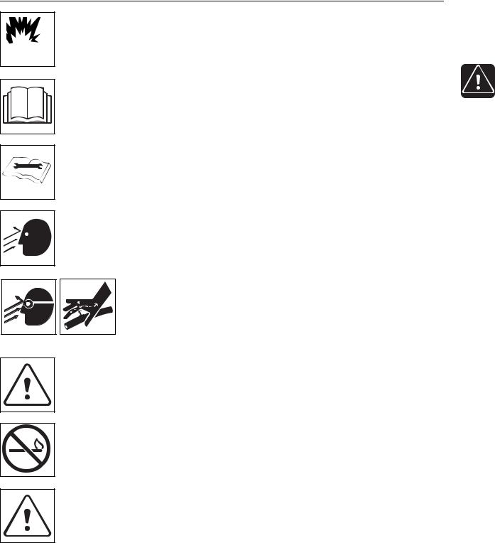
Safety Alerts
Moving digging teeth will kill you or cut off arm or leg. Stay away.
Turning shaft will kill you or crush arm or leg. Stay away.
 Electric shock. Contacting electric lines will cause death or serious injury. Know location of lines and stay away.
 Deadly gases. Lack of oxygen or presence of gas will cause sickness or death. Provide ventilation.
 Jobsite hazards could cause death or serious injury. Use correct equipment and work methods. Use and maintain proper safety equipment.
 Crushing weight could cause death or serious injury. Use proper procedures and equipment or stay away.
Moving parts could cut off hand or foot. Stay away.
CMW
R150/R230/R300 Operator’s Manual
Safety Alerts
Safety - 15
 Explosion possible. Serious injury or equipment damage could occur. Follow directions carefully.
 Incorrect procedures could result in death, injury, or property damage. Learn to use equipment correctly.
 Improper control function could cause death or serious injury. If control does not work as described in instructions, stop machine and have it serviced.
 Looking into fiber optic cable could result in permanent vision damage. Do not look into ends of fiber optic or unidentified cable.
 Pressurized fluid or air could pierce skin and cause injury or death. Stay away.
 Runaway possible. Machine could run over you or others. Learn how to use all controls. Start and operate only from operator’s position.
 Fire or explosion possible. Fumes could ignite and cause burns. No smoking, no flame, no spark.
 Moving traffic - hazardous situation. Death or serious injury could result. Avoid moving vehicles, wear high visibility clothing, post appropriate warning signs.
CMW

Safety - 16
R150/R230/R300 Operator’s Manual
Safety Alerts
Tipover possible. Machine can tip over and crush you.
•Always operate with load end uphill.
•Always carry load low. High load can cause tipping, loss of load or loss of visibility.
•Never jerk control levers. Use a steady even motion.
Flying objects may cause injury. Wear hard hat and safety glasses.
Hot parts may cause burns. Do not touch until cool.
 Exposure to high noise levels may cause hearing loss. Wear hearing protection.
Fall possible. Slips or trips may result in injury. Keep area clean.
Battery acid may cause burns. Avoid contact.
 Improper handling or use of chemicals may result in illness, injury, or equipment damage. Follow instructions on labels and in material safety data sheets (MSDS).
CMW

R150/R230/R300 Operator’s Manual |
Safety - 17 |
Emergency Procedures
Emergency Procedures
Before operating any equipment, review emergency procedures and check that all safety precautions have been taken.
EMERGENCY SHUTDOWN: Release all controls (including cruise control pedal) and turn ignition switch to OFF.
Electric Strike Description
When working near electric cables, remember the following:
•Electricity follows all paths to ground, not just path of least resistance.
•Pipes, hoses, and cables will conduct electricity back to all equipment.
•Low voltage current can injure or kill. Almost one-third of work-related electrocutions result from contact with less than 440 volts.
Most electric strikes are not noticeable, but indications of a strike include:
•power outage
•smoke
•explosion
•popping noises
•arcing electricity
If any of these occur, assume an electric strike has occurred.
CMW

Safety - 18
R150/R230/R300 Operator’s Manual
Emergency Procedures
If an Electric Line is Damaged
If you suspect an electric line has been damaged and you are on platform, DO NOT MOVE. Remain on platform and take the following actions. The order and degree of action will depend upon the situation.
•Warn people nearby that an electric strike has occurred. Instruct them to leave the area and contact utility.
•Raise front end and attachments and drive from immediate area.
•Contact utility company to shut off power.
•Do not return to jobsite or allow anyone into area until given permission by utility company.
If you suspect an electric line has been damaged and you are off platform, DO NOT TOUCH UNIT. Take the following actions. The order and degree of action will depend upon the situation.
•LEAVE AREA. The ground surface may be electrified, so take small steps with feet close together to reduce the hazard of being shocked from one foot to the other. For more information, contact your Ditch Witch dealer.
•Contact utility company to shut off power.
•Do not return to jobsite or allow anyone into area until given permission by utility company.
If a Gas Line is Damaged
If you suspect a gas line has been damaged, take the following actions. The order and degree of action will depend on the situation.
•Immediately shut off engine(s), if this can be done safely and quickly.
•Remove any ignition source(s), if this can be done safely and quickly.
•Warn others that a gas line has been cut and that they should leave the area.
•Leave jobsite as quickly as possible.
•Immediately call your local emergency phone number and utility company.
•If jobsite is along street, stop traffic from driving near jobsite.
•Do not return to jobsite until given permission by emergency personnel and utility company.
CMW

R150/R230/R300 Operator’s Manual
Emergency Procedures
If a Fiber Optic Cable is Damaged
Safety - 19
Do not look into cut ends of fiber optic or unidentified cable. Vision damage can occur.
If Machine Catches on Fire
Perform emergency shutdown procedure and then take the following actions. The order and degree of action will depend on the situation.
•Immediately move battery disconnect switch (if equipped) to disconnect position.
•If fire is small and fire extinguisher is available, attempt to extinguish fire.
•If fire cannot be extinguished, leave area as quickly as possible and contact emergency personnel.
CMW
Safety - 20
R150/R230/R300 Operator’s Manual
Emergency Procedures
CMW

R150/R230/R300 Operator’s Manual |
Controls - 21 |
Controls
Chapter Contents
Gauges and Indicators . . . . . . . . . . . . . . . . . . . . . 22
Controls . . . . . . . . . . . . . . . . . . . . . . . . . . . . . . . . . 24
• |
R150/R150E . . . . . . . . . . . . . . . . . . . . . . . . . . . . . . . . . . . . . . . . . . . . . |
.24 |
• |
R230/R300 . . . . . . . . . . . . . . . . . . . . . . . . . . . . . . . . . . . . . . . . . . . . . . . |
28 |
• |
R150/R230/R300 . . . . . . . . . . . . . . . . . . . . . . . . . . . . . . . . . . . . . . . . . . |
32 |
CMW

Controls - 22
R150/R230/R300 Operator’s Manual
Gauges and Indicators
Gauges and Indicators
|
|
|
|
|
|
|
|
|
|
|
|
|
|
|
|
|
|
|
|
|
|
|
|
|
|
|
|
|
|
|
|
|
|
|
|
|
|
|
|
|
|
|
|
|
|
|
|
|
|
|
|
|
|
|
|
|
|
|
|
|
|
|
|
|
|
|
|
|
|
|
|
|
|
|
1. |
Auxiliary power outlet (R150E/R230/R300 |
3. |
Hydraulic fluid sight glass |
|||||||||||
|
only) |
|
4. |
Hourmeter (optional) |
||||||||||
2. |
Fuel sight glass |
|
||||||||||||
|
|
|
|
|
|
|||||||||
|
|
|
|
|
|
|
|
|
|
|
|
|
|
|
Item |
Description |
|
|
|
|
Notes |
||||||||
|
|
|
|
|
|
|
|
|
|
|
|
|
||
1. |
Auxiliary power outlet |
To operate work lights or |
Not available on R150 with rope start. |
|||||||||||
|
|
|
|
|
|
|
|
|
other 12V devices, plug into |
|
||||
|
|
|
|
|
|
|
|
|
outlet. |
|
|
|
|
|
|
|
|
|
|
|
|
|
|
|
|
|
|
||
2. |
Fuel tank sight window |
Shows level of fuel in tank. |
|
|||||||||||
|
|
|
|
|
|
|
|
|
|
|
|
|
||
3. |
Hydraulic fluid sight |
Shows level of hydraulic fluid |
|
|||||||||||
|
glass |
in tank. Maintain fluid at |
|
|
|
|
||||||||
|
|
|
|
|
|
|
|
|
halfway point on glass. |
|
|
|
|
|
|
|
|
|
|
|
|
|
|
|
|
|
|
|
|
CMW
R150/R230/R300 Operator’s Manual
Gauges and Indicators
Controls - 23
Item |
Description |
Notes |
||||
|
|
|
|
|
|
|
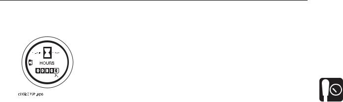
4. Hourmeter (optional) |
Displays engine operating |
Use these times to schedule service. |
||||
|
|
|
|
|
time. |
|
|
|
|
|
|
|
|
|
|
|
|
|
|
|
|
|
|
|
|
|
|
|
|
|
|
|
|
|
|
|
|
|
|
|
|
CMW

Controls - 24 |
R150/R230/R300 Operator’s Manual |
|
Controls |
Controls |
|
R150/R150E |
|
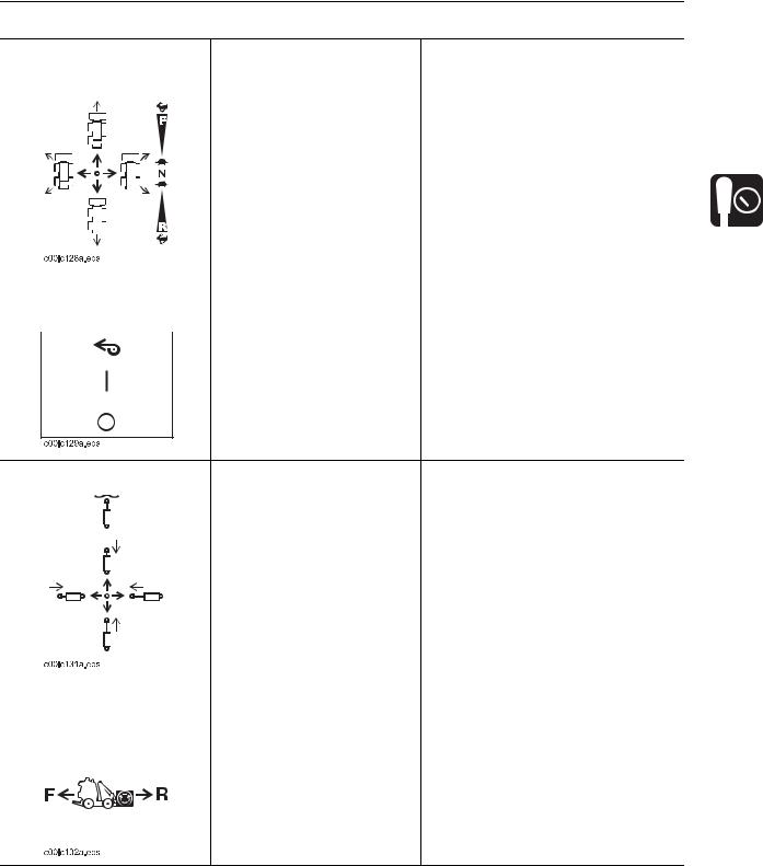
1. |
Ground drive control |
6. |
Choke (R150)/manual start switch (R150E) |
2. |
Traction assist switch |
7. |
Rope start |
3. |
Throttle switch |
8. |
Ignition switch |
4. |
Front end lift control |
9. |
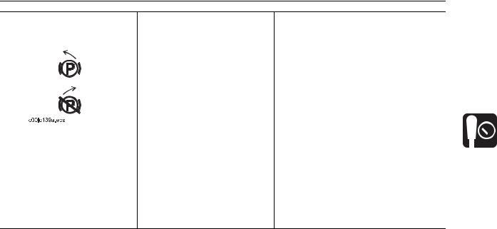
Parking brake |
5. |
Front end drive control |
10. |
Cruise control pedal |
CMW
R150/R230/R300 Operator’s Manual
Controls
Controls - 25
Item |
Description |
Notes |
|||
|
|
|
|
|
|
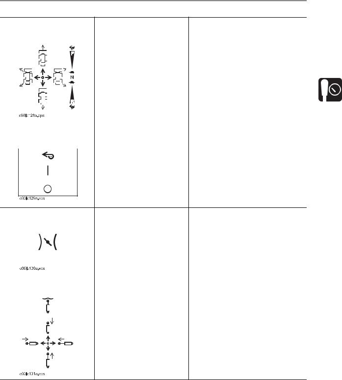
1. |
Ground drive control |
To move forward, push. |
To make a gradual turn, move control |
||
|
|
|
|
|
halfway between desired directions |
|
|
|
|
|
|
|
|
|
|
To move backward, pull. |
and return to center. Unit will remain |
|
|
|
|
To turn right, move to right. |
articulated until it is returned to center. |
|
|
|
|
IMPORTANT: As long as control is |
|
|
|
|
|
|
|
|
|
|
|
To turn left, move to left. |
moved to right or left, unit is |
|
|
|
|
To go faster in any direction, |
articulating and turning is tightened. |
|
|
|
|
|
|
|
|
|
|
move control farther from |
|
|
|
|
|
neutral position. |
|
|
|
|
|
|
|
|
|
|
|
To stop, release. |
|
|
|
|
|
|
|
2. |
Traction assist switch |
To allow maximum power to |
Use when working on a slope to |
||
|
|
|
|
tires, press top. |
lessen undesired movement. |
|
|
|
|
||
To return to normal operation, press bottom.
3. |
Throttle switch |
To set engine speed for |
||
|
|
|
|
operation, press top. |
|
|
|
|
|
|
|
|
|
To set speed to middle range |
|
|
|
|
for transport, move to center |
|
|
|
|
position |
|
|
|
|
To decrease speed to idle, |
|
|
|
|
|
|
|
|
|
press bottom. |
|
|
|
|
|
4. |
Front end lift control |
To lower trencher, push. |
||
|
|
|
|
To raise trencher, pull. |
|
|
|
|
|
CMW
Controls - 26
R150/R230/R300 Operator’s Manual
Controls
Item |
Description |
Notes |
|||||
|
|
|
|
|
|
|
|
5. |
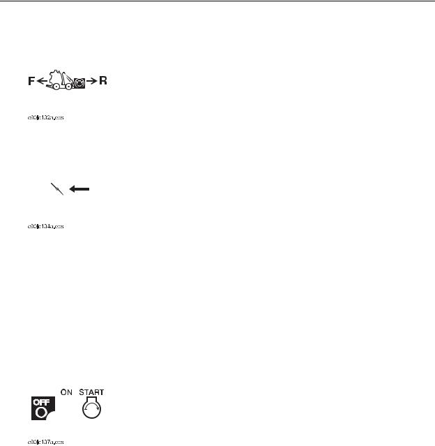
Front end drive control |
To engage front end drive in |
|
||||
|
|
|
|
|
|
reverse, lift lever release and |
|
|
|
|
|
|
|
|
|
|
|
|
|
|
|
move to right. |
|
|
|
|
|
|
|
To engage front end drive in |
|
|
|
|
|
|
|
forward, lift lever release and |
|
|
|
|
|
|
|
move to left. |
|
|
|
|
|
|
|
|
|
6. |
Choke/manual start |
Choke (R150) |
This valve regulates air/fuel mixture. |
||||
|
switch |
To help start cold engine, |
|
||||
|
|
|
|
|
|
|
|
|
|
|
|
|
|
close valve. |
|
|
|
|
|
|
|
Manual start switch (R150E) |
IMPORTANT: R150E units have |
|
|
|
|
|
|
||
|
|
|
|
|
|
To manually start engine |
automatic choke feature. |
|
|
|
|
|
|
|
|
|
|
|
|
|
|
when electric starter doesn’t |
|
|
|
|
|
|
|
|
|
|
|
|
|
|
|
work, move switch to right, |
|
|
|
|
|
|
|
turn on power switch and pull |
|
|
|
|
|
|
|
rope start. |
|
|
|
|
|
|
|
|
|
7. |
Rope start |
To start engine, pull rope. |
Ignition switch must be on for this |
||||
|
|
|
|
|
|
|
control to function. |
|
|
|
|
|
|
|
If engine does not start after three |
|
|
|
|
|
|
|
pulls, turn power switch off and check |
|
|
|
|
|
|
|
for fuel blockage or electrical system |
|
|
|
|
|
|
|
problems. |
|
|
|
|
|
|
|
|
8. |
Ignition switch |
R150 |
|
||||
|
|
|
|
|
|
To start engine, insert key and |
|
|
|
|
|
|
|
turn clockwise. Pull rope start. |
|
|
|
|
|
|
|
|
|
|
|
|
|
|
|
To stop engine, turn key |
|
|
|
|
|
|
|
|
|
|
|
|
|
|
|
counterclockwise. |
|
|
|
|
|
|
|
R150E |
IMPORTANT: |
|
|
|
|
|
|
||
|
|
|
|
|
|
To start engine, insert key and |
• If engine does not start, turn key |
|
|
|
|
|
|
turn clockwise. |
to OFF and then restart. |
|
|
|
|
|
|
To stop engine, turn key |
• Do not allow starter motor to run |
|
|
|
|
|
|
continuously for more than 20 |
|
|
|
|
|
|
|
counterclockwise. |
|
|
|
|
|
|
|
seconds. |
|
|
|
|
|
|
|
|
|
|
|
|
|
|
|
|
|
CMW
R150/R230/R300 Operator’s Manual
Controls
Controls - 27
Item |
Description |
Notes |
||||
|
|
|
|
|
|
|
9. Parking brake lever |
To engage, move handle to |
IMPORTANT: |
||||
|
|
|
|
|
left. |
• Move unit slightly to ensure |
|
|
|
|
|
||
|
|
|
|
|
|
|
|
|
|
|
|
To disengage, move handle |
parking brake pins are engaged. |
|
|
|
|
|
to right. |
• It might be necessary to move |
|
|
|
|
|
||
|
|
|
|
|
|
|
|
|
|
|
|
|
unit slightly to disengage parking |
|
|
|
|
|
|
brake. |
|
|
|
|
|
|
|
|
|
|
|
|
|
|
10. Cruise control pedal |
To maintain ground drive and |
NOTICE: Pedal must return to neutral |
||||
|
|
|
|
|
front end drive settings, press |
when released. Never tie down or use |
|
|
|
|
|
pedal and release handles. |
anything other than foot to hold pedal |
|
|
|
|
|
|
down. |
To adjust settings, grab drive handles, step off pedal, adjust drive settings, press pedal and release handles.
CMW

Controls - 28
R150/R230/R300 Operator’s Manual
Controls
R230/R300
|
|
|
|
|
1. |
Ground drive control |
6. |
Choke |
|
2. |
Traction assist switch |
7. |
Throttle |
|
3. |
Front end lift control |
8. |
Ignition switch |
|
4. |
Front end drive control |
9. |
Parking brake |
|
5. |
Remote throttle control (optional) |
10. |
Cruise control pedal |
|
CMW
R150/R230/R300 Operator’s Manual
Controls
Controls - 29
Item |
Description |
Notes |
|||
|
|
|
|
|
|
1. |
Ground drive control |
To move forward, push. |
To make a gradual turn, move control |
||
|
|
|
|
|
halfway between desired directions |
|
|
|
|
|
|
|
|
|
|
To move backward, pull. |
and return to center. Unit will remain |
|
|
|
|
To turn right, move to right. |
articulated until it is returned to center. |
|
|
|
|
IMPORTANT: As long as control is |
|
|
|
|
|
|
|
|
|
|
|
To turn left, move to left. |
moved to right or left, unit is |
|
|
|
|
To go faster in any direction, |
articulating and turning is tightened. |
|
|
|
|
|
|
|
|
|
|
move control farther from |
|
|
|
|
|
neutral position. |
|
|
|
|
|
|
|
|
|
|
|
To stop, release. |
|
|
|
|
|
|
|
2. |
Traction assist switch |
To allow maximum power to |
Use when working on a slope to |
||
|
|
|
|
tires, press top. |
lessen undesired track movement. |
|
|
|
|
||
To return to normal operation, press bottom.
3. |
Front end lift control |
To retract primary cylinder or |
|
||
|
|
|
|
lower trencher, push. |
IMPORTANT: Front end will drop |
|
|
|
|
||
|
|
|
|
To float, push forward to |
|
|
|
|
|
detent. |
when unit is put in float position. |
|
|
|
|
To extend primary cylinder or |
|
|
|
|
|
raise trencher, pull. |
|
|
|
|
|
To retract secondary cylinder, |
|
|
|
|
|
move to left. |
|
|
|
|
|
To extend secondary cylinder, |
|
|
|
|
|
move to right. |
|
|
|
|
|
|
|
4. |
Front end drive control |
To engage front end drive in |
|
||
|
|
|
|
reverse, lift lever release and |
|
|
|
|
|
move to right. |
|
|
|
|
|
To engage front end drive in |
|
|
|
|
|
forward, lift lever release and |
|
|
|
|
|
move to left. |
|
CMW
Loading...