


 Loading...
RT12/RT16/RT20/RT24
Operator’s
Manual
CMW® |
Issue 1.0 |
053-2439 |
|
Original Translation |
|

RT12/RT16/RT20/RT24 Operator’s Manual |
Overview - 1 |
Overview
Chapter Contents
Serial Number Location . . . . . . . . . . . . . . . . . . . . . . 2
Intended Use . . . . . . . . . . . . . . . . . . . . . . . . . . . . . . . 3
Equipment Modification . . . . . . . . . . . . . . . . . . . . . . 3
Unit Components . . . . . . . . . . . . . . . . . . . . . . . . . . . 3
Operator Orientation. . . . . . . . . . . . . . . . . . . . . . . . . 4
About This Manual . . . . . . . . . . . . . . . . . . . . . . . . . . 4
• |
Bulleted Lists. . . . . . . . . . . . . . . . . . . . . . . . . . . . . . . . . . . . . . . . . . . . . . |
4 |
• |
Numbered Lists . . . . . . . . . . . . . . . . . . . . . . . . . . . . . . . . . . . . . . . . . . . . |
4 |
CMW

Overview - 2
RT12/RT16/RT20/RT24 Operator’s Manual
Serial Number Location
Serial Number Location
Record serial numbers and date of purchase in spaces provided. Trencher serial number is located as shown.
Item |
date of manufacture
date of purchase
trencher serial number
trailer serial number
engine serial number
CMW

RT12/RT16/RT20/RT24 Operator’s Manual
Intended Use
Intended Use
Overview - 3
The RT12, RT16, RT20, and RT24 pedestrian trenchers are designed to install buried cable and pipe to depths of 48” (1220 mm) and widths of 8” (200 mm). These units are intended for operation in ambient temperatures from 20° to 115°F (-7° to 46°C). Use in any other way is considered contrary to the intended use.
RT12, RT16, RT20, and RT24 units should be used with genuine Ditch Witch chain, teeth, and sprockets. They should be operated, serviced, and repaired only by persons familiar with their particular characteristics and acquainted with the relevant safety procedures.
Equipment Modification
This equipment was designed and built in accordance with applicable standards and regulations. Modification of equipment could mean that it will no longer meet regulations and may not function properly or in accordance with the operating instructions. Modification of equipment should only be made by competent personnel possessing knowledge of applicable standards, regulations, equipment design functionality/requirements and any required specialized testing.
Unit Components
1. |
Control console |
3. |
Digging boom and chain |
2. |
Engine |
4. |
Trail wheel |
CMW

Overview - 4
RT12/RT16/RT20/RT24 Operator’s Manual
Operator Orientation
Operator Orientation
1. Front of unit
2. Right side of unit
3. Rear of unit
4. Left side of unit
About This Manual
This manual contains information for the proper use of this machine. See the beige Operation Overview pages for basic operating procedures. Cross references such as “See page 50” will direct you to detailed procedures.
Bulleted Lists
Bulleted lists provide helpful or important information or contain procedures that do not have to be performed in a specific order.
Numbered Lists
Numbered lists contain illustration callouts or list steps that must be performed in order.
CMW

RT12/RT16/RT20/RT24 Operator’s Manual |
Foreword - 5 |
Foreword
This manual is an important part of your equipment. It provides safety information and operation instructions to help you use and maintain your Ditch Witch equipment.
Read this manual before using your equipment. Keep it with the equipment at all times for future reference. If you sell your equipment, be sure to give this manual to the new owner.
If you need a replacement copy, contact your Ditch Witch dealer. If you need assistance in locating a dealer, visit our website at www.ditchwitch.com or write to the following address:
The Charles Machine Works, Inc.
Attn: Marketing Department
PO Box 66
Perry, OK 73077-0066
USA
The descriptions and specifications in this manual are subject to change without notice. The Charles Machine Works, Inc. reserves the right to improve equipment. Some product improvements may have taken place after this manual was published. For the latest information on Ditch Witch equipment, see your Ditch Witch dealer.
Thank you for buying and using Ditch Witch equipment.
CMW

Foreword - 6 |
RT12/RT16/RT20/RT24 Operator’s Manual |
|
|
RT12/RT16/RT20/RT24
Operator’s Manual
Issue number 1.0/OM-12/11
Part number 053-2439
Copyright 2011
by The Charles Machine Works, Inc.


 , Ditch Witch, CMW, and Roto Witch are registered trademarks of The Charles Machine Works, Inc.
CMW

RT12/RT16/RT20/RT24 Operator’s Manual |
Contents - 7 |
Contents
Overview |
1 |
machine serial number, information about the type of work this machine is designed to perform, basic machine components, and how to use this manual
Foreword |
5 |
part number, revision level, and publication date of this manual, and factory contact information
Safety |
9 |
machine safety alerts and emergency procedures |
|
|
|
Controls |
21 |
machine controls, gauges, and indicators and how to use them |
|
|
|
Prepare |
31 |
procedures for inspecting and classifying the jobsite, planning the installation path, |
|
and preparing the jobsite for work |
|
|
|
Drive |
37 |
procedures for startup, cold start, driving, and shutdown |
|
|
|
Transport |
41 |
procedures for lifting, hauling, and towing |
|
|
|
Trench |
49 |
procedures for trenching |
|
|
|
Drill |
53 |
procedures for drilling |
|
|
|
Systems and Equipment |
61 |
chain, teeth, sprockets, and optional equipment |
|
|
|
Complete the Job |
69 |
procedures for backfilling and restoring the jobsite and rinsing and storing |
|
equipment |
|
|
|
Service |
71 |
service intervals and instructions for this machine including lubrication, replacement |
|
of wear items, and basic maintenance |
|
CMW
Contents - 8 |
RT12/RT16/RT20/RT24 Operator’s Manual |
|
|
|
|
Specifications |
95 |
machine specifications including weights, measurements, power ratings, and fluid |
|
capacities |
|
|
|
Support |
109 |
the warranty policy for this machine, and procedures for obtaining warranty |
|
consideration and training |
|
Service Record |
113 |
a record of major service performed on the machine
CMW

RT12/RT16/RT20/RT24 Operator’s Manual |
Safety - 9 |
Safety
Chapter Contents
Guidelines . . . . . . . . . . . . . . . . . . . . . . . . . . . . . . . . 10
Safety Alert Classifications . . . . . . . . . . . . . . . . . . 11
Safety Alerts . . . . . . . . . . . . . . . . . . . . . . . . . . . . . . 12
Emergency Procedures . . . . . . . . . . . . . . . . . . . . . 15
• |
Electric Strike Description . . . . . . . . . . . . . . . . . . . . . . . . . . . . . . . . . . . |
15 |
• If an Electric Line is Damaged . . . . . . . . . . . . . . . . . . . . . . . . . . . . . . . |
16 |
|
• If a Gas Line is Damaged . . . . . . . . . . . . . . . . . . . . . . . . . . . . . . . . . . . |
16 |
|
• If a Fiber Optic Cable is Damaged . . . . . . . . . . . . . . . . . . . . . . . . . . . . |
17 |
|
• |
If Machine Catches on Fire . . . . . . . . . . . . . . . . . . . . . . . . . . . . . . . . . . |
17 |
CMW
Safety - 10
RT12/RT16/RT20/RT24 Operator’s Manual
Guidelines
Guidelines
Follow these guidelines before operating any jobsite equipment:
•Complete proper training and read operator’s manual before using equipment.
•Contact your local One-Call (811 in USA) or the One-Call referral number (888-258-0808 in USA and Canada) to have underground utilities located before digging. Also contact any utilities that do not participate in the One-Call service.
•Classify jobsite based on its hazards and use correct tools and machinery, safety equipment, and work methods for jobsite.
•Mark jobsite clearly and keep spectators away.
•Wear personal protective equipment.
•Review jobsite hazards, safety and emergency procedures, and individual responsibilities with all personnel before work begins. Safety videos are available from your Ditch Witch dealer.
•Replace missing or damaged safety shields and safety signs.
•Use equipment carefully. Stop operation and investigate anything that does not look or feel right.
•Do not operate unit where flammable gas may be present.
•Contact your Ditch Witch dealer if you have any question about operation, maintenance, or equipment use.
CMW

RT12/RT16/RT20/RT24 Operator’s Manual |
Safety - 11 |
Safety Alert Classifications
Safety Alert Classifications
These classifications and the icons defined on the following pages work together to alert you to situations which could be harmful to you, jobsite bystanders or your equipment. When you see these words and icons in the book or on the machine, carefully read and follow all instructions. YOUR SAFETY IS AT STAKE.
Watch for the three safety alert levels: DANGER, WARNING and CAUTION. Learn what each level means.
 indicates a hazardous situation that, if not avoided, will result in death or serious injury. This signal word is to be limited to the most extreme situations.
 indicates a hazardous situation that, if not avoided, could result in death or serious injury.
 indicates a hazardous situation that, if not avoided, could result in minor or moderate injury.
Watch for two other words: NOTICE and IMPORTANT.
NOTICE indicates information considered important, but not hazard-related (e.g., messages relating to property damage).
IMPORTANT can help you do a better job or make your job easier in some way.
CMW
Safety - 12
RT12/RT16/RT20/RT24 Operator’s Manual
Safety Alerts
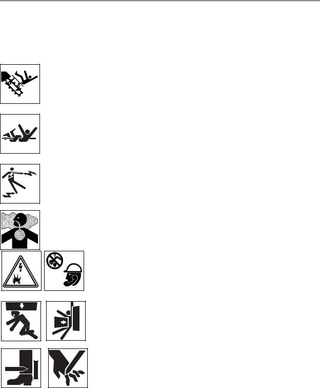
Safety Alerts
 Moving digging teeth will kill you or cut off arm or leg. Stay away.
 Turning shaft will kill you or crush arm or leg. Stay away.
 Electric shock. Contacting electric lines will cause death or serious injury. Know location of lines and stay away.
 Deadly gases. Lack of oxygen or presence of gas will cause sickness or death. Provide ventilation.
 Jobsite hazards could cause death or serious injury. Use correct equipment and work methods. Use and maintain proper safety equipment.
 Crushing weight could cause death or serious injury. Use proper procedures and equipment or stay away.
 Moving parts could cut off hand or foot. Stay away.
CMW

RT12/RT16/RT20/RT24 Operator’s Manual
Safety Alerts
Safety - 13
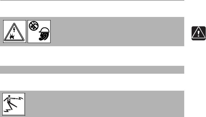
 Explosion possible. Serious injury or equipment damage could occur. Follow directions carefully.
 Incorrect procedures could result in death, injury, or property damage. Learn to use equipment correctly.
 Improper control function could cause death or serious injury. If control does not work as described in instructions, stop machine and have it serviced.
 Looking into fiber optic cable could result in permanent vision damage. Do not look into ends of fiber optic or unidentified cable.
 Pressurized fluid or air could pierce skin and cause injury or death. Stay away.
 Fire or explosion possible. Fumes could ignite and cause burns. No smoking, no flame, no spark.
 Moving traffic - hazardous situation. Death or serious injury could result. Avoid moving vehicles, wear high visibility clothing, post appropriate warning signs.
CMW

Safety - 14
RT12/RT16/RT20/RT24 Operator’s Manual
Safety Alerts
 Hot pressurized cooling system fluid could cause serious burns. Allow to cool before servicing.
 Flying objects may cause injury. Wear hard hat and safety glasses.
 Hot parts may cause burns. Do not touch until cool.
 Exposure to high noise levels may cause hearing loss. Wear hearing protection.
 Fall possible. Slips or trips may result in injury. Keep area clean.
 Battery acid may cause burns. Avoid contact.
 Improper handling or use of chemicals may result in illness, injury, or equipment damage. Follow instructions on labels and in material safety data sheets (MSDS).
CMW
RT12/RT16/RT20/RT24 Operator’s Manual
Emergency Procedures
Emergency Procedures
Safety - 15
 Jobsite hazards could cause death or serious injury. Use correct equipment and work methods. Use and maintain proper safety equipment.
Before operating any equipment, review emergency procedures and check that all safety precautions have been taken.
EMERGENCY SHUTDOWN - Release all controls and turn ignition switch to STOP.
Electric Strike Description
 Electric shock. Contacting electric lines will cause death or serious injury. Know location of lines and stay away.
When working near electric cables, remember the following:
•Electricity follows all paths to ground, not just path of least resistance.
•Pipes, hoses, and cables will conduct electricity back to all equipment.
•Low voltage current can injure or kill. Many work-related electrocutions result from contact with less than 440 volts.
Most electric strikes are not noticeable, but indications of a strike include:
•power outage
•smoke
•explosion
•popping noises
•arcing electricity
If any of these occur, assume an electric strike has occurred.
CMW

Safety - 16
RT12/RT16/RT20/RT24 Operator’s Manual
Emergency Procedures
If an Electric Line is Damaged
If you suspect an electric line has been damaged and you are near pedestrian unit, DO NOT MOVE and do not touch unit. Take the following actions. The order and degree of action will depend upon the situation.
•Warn people nearby that an electric strike has occurred. Instruct them to leave the area and contact utility.
•Do not allow anyone into area until given permission by utility company.
•Do not allow anyone to touch equipment.
If a Gas Line is Damaged
 Fire or explosion possible. Fumes could ignite and cause burns. No smoking, no flame, no spark.
 Explosion possible. Serious injury or equipment damage could occur. Follow directions carefully.
If you suspect a gas line has been damaged, take the following actions. The order and degree of action will depend on the situation.
•Immediately shut off engine(s), if this can be done safely and quickly.
•Remove any ignition source(s), if this can be done safely and quickly.
•Warn others that a gas line has been cut and that they should leave the area.
•Leave jobsite as quickly as possible.
•Immediately call your local emergency phone number and utility company.
•If jobsite is along street, stop traffic from driving near jobsite.
•Do not return to jobsite until given permission by emergency personnel and utility company.
CMW

RT12/RT16/RT20/RT24 Operator’s Manual
Emergency Procedures
If a Fiber Optic Cable is Damaged
Safety - 17
Do not look into cut ends of fiber optic or unidentified cable. Vision damage can occur.
If Machine Catches on Fire
Perform emergency shutdown procedure and then take the following actions. The order and degree of action will depend on the situation.
•Immediately move battery disconnect switch (if equipped) to disconnect position.
•If fire is small and fire extinguisher is available, attempt to extinguish fire.
•If fire cannot be extinguished, leave area as quickly as possible and contact emergency personnel.
CMW

Safety - 18
RT12/RT16/RT20/RT24 Operator’s Manual
Emergency Procedures
CMW

RT12/RT16/RT20/RT24 Operator’s Manual |
Operation Overview - 19 |
Operation Overview
Chapter Contents
Planning. . . . . . . . . . . . . . . . . . . . . . . . . . . . . . . . . . 20
Trenching. . . . . . . . . . . . . . . . . . . . . . . . . . . . . . . . . 20
Leaving Jobsite. . . . . . . . . . . . . . . . . . . . . . . . . . . . 20
CMW
Operation Overview - 20
RT12/RT16/RT20/RT24 Operator’s Manual
Planning
Planning
1.Gather information about jobsite. See page 31.
2.Inspect jobsite. See page 33.
3.Classify jobsite. See page 34.
4.Select best chain type and tooth pattern for your application. See page 62.
5.Consider optional equipment, if necessary. See page 64.
6.Check supplies and prepare equipment. See page 36.
7.Load unit onto trailer. See page 43.
Trenching
1.Unload unit from trailer. See page 46.
2.Leave optional backfill blade, if equipped, in stowed position with digging boom low to ground.
3.Start unit. See page 38.
4.Drive to starting point of trench. See page 39.
5.Dig the trench. See page 51.
6.Shut down unit. See page 39.
Leaving Jobsite
1.Restore the jobsite. See page 70.
2.Rinse unit and stow tools. See page 70.
3.Load unit onto trailer. See page 43.
CMW

RT12/RT16/RT20/RT24 Operator’s Manual |
Controls - 21 |
Controls
Chapter Contents
Control Console . . . . . . . . . . . . . . . . . . . . . . . . . . . 22
RT12 Engine Controls . . . . . . . . . . . . . . . . . . . . . . 26
RT16 Engine Controls . . . . . . . . . . . . . . . . . . . . . . 27
RT20 and RT24 Engine Controls . . . . . . . . . . . . . . 29
CMW
Controls - 22
RT12/RT16/RT20/RT24 Operator’s Manual
Control Console
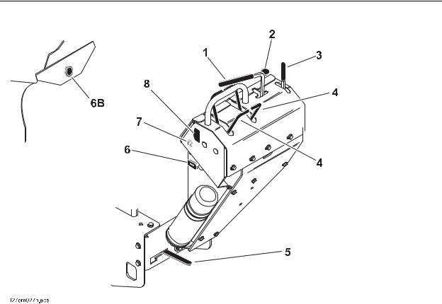
Control Console
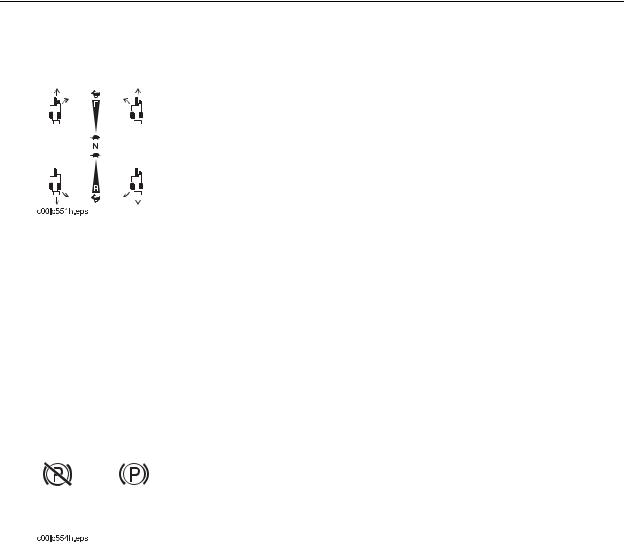
1.Digging chain/Roto Witch® control
2.Selector valve control (Roto Witch® option)
3.Boom lift control
4.Speed/direction controls
5.Parking brake lever
6.Hourmeter/tachometer (RT16 option) 6B. Hourmeter (RT 12 option)
7.Ignition Switch (RT12)
8.Throttle switch (RT12)
CMW

RT12/RT16/RT20/RT24 Operator’s Manual
Control Console
Controls - 23
Item |
Description |
Notes |
||||
|
|
|
|
|
|
|
1. |
Digging chain control |
To start digging chain, pull |
NOTICE: Trenching movement is |
|||
|
|
|
|
|
toward operator, then push |
always backward (toward you). |
|
|
|
|
|
||
|
|
|
|
|
down to dig position. |
|
|
|
|
|
|
To stop digging chain, release |
|
|
|
|
|
|
control. |
|
|
|
|
|
|
To dislodge a rock or other |
NOTICE: To dislodge obstructions, |
|
|
|
|
|
obstruction, pull up on control |
reverse chain. |
|
|
|
|
|
||
|
|
|
|
|
to reverse chain. |
NOTICE: Do not attempt to travel with |
|
|
|
|
|
IMPORTANT: This control |
|
|
|
|
|
|
digging chain control pulled up (chain |
|
|
|
|
|
|
changes function when |
in reverse position). |
|
|
|
|
|
equipped with optional Roto |
|
|
|
|
|
|
Witch. |
|
|
|
|
|
|
In drill mode: |
|
|
|
|
|
|
|
|
|
|
|
|
|
To drill clockwise, push down. |
|
|
|
|
|
|
To stop drill rotation, release |
|
|
|
|
|
|
control. |
|
|
|
|
|
|
To drill counterclockwise, pull |
|
|
|
|
|
|
|
|
|
|
|
|
|
up. |
|
|
|
|
|
|
|
|
2. |
Selector valve control |
Optional selector valve |
|
|||
|
|
|
|
|
control used on units |
|
|
|
|
|
|
|
|
|
|
|
|
|
equipped with Roto Witch to |
|
|
|
|
|
|
change function of digging |
|
|
|
|
|
|
|
|
|
|
|
|
|
chain control. |
|
|
|
|
|
|
To select drill mode, pull up. |
|
|
|
|
|
|
To select dig mode, push |
|
|
|
|
|
|
|
|
|
|
|
|
|
down. |
|
|
|
|
|
|
|
|
3. |
Boom lift control |
To lower boom, push. |
NOTICE: Keep digging boom low |
|||
|
|
|
|
|
|
when operating on a slope or |
|
|
|
|
|
|
|
|
|
|
|
|
To raise boom, pull. |
transporting. Drive slowly and |
|
|
|
|
|
|
cautiously at all times. |
|
|
|
|
|
|
|
|
|
|
|
|
|
|
CMW
Controls - 24
RT12/RT16/RT20/RT24 Operator’s Manual
Control Console
Item |
Description |
Notes |
||||
|
|
|
|
|
|
|
4. |
Speed/direction |
To drive straight forward, |
NOTICE: Trenching movement is |
|||
|
controls |
push BOTH controls slowly |
always backward (toward you). |
|||
|
|
|
|
|
forward. |
|
|
|
|
|
|
|
|
|
|
|
|
|
To drive straight in reverse, |
|
|
|
|
|
|
|
|
|
|
|
|
|
|
|
|
|
|
|
|
pull BOTH controls slowly |
|
|
|
|
|
|
rearward. |
|
|
|
|
|
|
To turn left, move RIGHT |
|
|
|
|
|
|
|
|
|
|
|
|
|
speed/direction control for |
|
|
|
|
|
|
forward or reverse. |
|
|
|
|
|
|
To turn right, move LEFT |
|
|
|
|
|
|
speed/direction control for |
|
|
|
|
|
|
forward or reverse. |
|
|
|
|
|
|
To go faster in any direction, |
|
|
|
|
|
|
move controls farther from |
|
|
|
|
|
|
neutral position. |
|
|
|
|
|
|
To stop, release controls. |
|
|
|
|
|
|
|
|
5. |
Parking brake |
To engage parking brake, |
IMPORTANT: |
|||
|
|
|
|
|
move lever to the right. |
• Move unit slightly to ensure |
|
|
|
|
|
||
|
|
|
|
|
|
|
|
|
|
|
|
To disengage parking brake, |
parking brake pins are engaged. |
|
|
|
|
|
move lever left to notch. |
• It might be necessary to move |
|
|
|
|
|
|
|
|
|
|
|
|
|
unit slightly to disengage parking |
|
|
|
|
|
|
brake. |
|
|
|
|
|
|
|
|
|
|
|
|
|
|
CMW

RT12/RT16/RT20/RT24 Operator’s Manual
Control Console
Controls - 25
Item |
Description |
Notes |
||||
|
|
|
|
|
|
|
6. Hourmeter/tachometer |
Displays engine operating |
Use engine operating times to |
||||
(RT16 option) |
time and engine speed. |
schedule service. |
||||
|
|
|
|
|
|
|
|
|
|
|
|
|
|
|
|
|
|
|
|
|
6B. (RT12 option)
|
|
|
|
|
|
|
|
|
|
|
|
|
|
|
|
|
|
|
c00ic259h.eps |
|
|||
|
|
|
|
|
|
7. Ignition switch (RT12) |
To start engine, turn key all |
||||
|
|
|
|
|
the way clockwise. Release |
|
|
|
|
|
|
|
|
|
|
|
key as engine starts. |
|
|
|
|
|
To stop engine, turn key |
|
|
|
|
|
counterclockwise. |
|
|
|
|
|
|
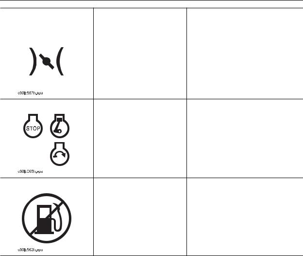
8. Throttle control (RT12) |
To increase engine speed, |
Start unit with throttle switch in the low |
||
|
|
|
press bottom. |
position. |
|
|
|
||
|
|
|
To decrease engine speed, |
|
|
|
|
press top. |
|
|
|
|
|
|
c00ic243h.eps
CMW

Controls - 26
RT12/RT16/RT20/RT24 Operator’s Manual
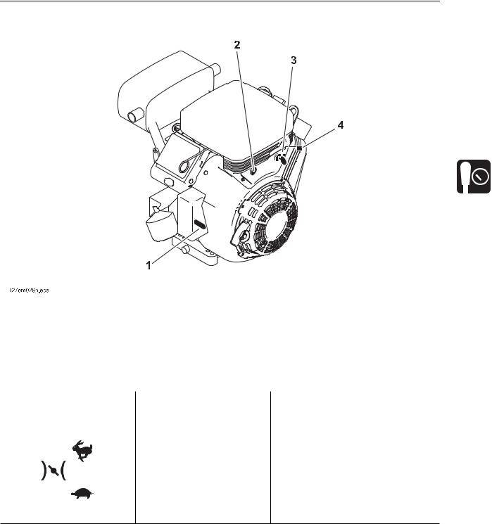
RT12 Engine Controls
RT12 Engine Controls
1
t27om070h.eps
1. |
Fuel shut-off valve |
|
|
||
|
|
|
|
|
|
Item |
Description |
Notes |
|||
|
|
|
|
|
|
1. |
Fuel shut-off valve |
To stop fuel flow from fuel |
Close valve when transporting unit to |
||
|
|
|
|
tank to engine, slide lever |
or from jobsite, or whenever machine |
|
|
|
|
||
|
|
|
|
away from engine. |
is parked. |
|
|
|
|
To allow fuel flow, slide lever |
|
|
|
|
|
toward engine. |
|
|
|
|
|
|
|
|
|
|
|
|
|
CMW
RT12/RT16/RT20/RT24 Operator’s Manual
RT16 Engine Controls
RT16 Engine Controls
Controls - 27
1. |
Throttle control |
3. |
Ignition switch |
|
2. |
Choke control |
4. |
Fuel shut-off valve |
|
|
|
|
|
|
Item |
Description |
Notes |
||
|
|
|
|
|
1. |
Throttle control |
To increase engine speed, |
||
|
|
|
pull up. |
|
|
|
|
|
|
|
|
|
To decrease engine speed, |
|
|
|
|
push down. |
|
|
|
|
|
|
c00ic243h.eps
CMW
Controls - 28
RT12/RT16/RT20/RT24 Operator’s Manual
RT16 Engine Controls
Item |
Description |
Notes |
|
|
|
|
|
2. Choke control |
To close choke valve, pull |
This valve can be closed to enrich |
|
|
|
choke control. |
air/fuel mixture and help start cold |
|
|
||
|
|
|
engine. |
|
|
|
Open choke valve after engine runs |
|
|
|
for a few seconds. |
|
|
|
|
3. Ignition switch |
To start engine, turn key all |
|
|
|
the way clockwise. Release |
|
|
|
|
|
key as engine starts. |
|
|
To stop engine, turn key |
|
|
counterclockwise. |
|
|
|
4. Fuel shut-off valve |
To stop fuel flow from fuel |
Close valve when transporting unit to |
|
|
|
tank to engine, turn valve |
or from jobsite, or whenever machine |
|
|
||
|
|
clockwise. |
is parked. |
|
|
To allow fuel flow, turn valve |
|
|
|
counterclockwise. |
|
|
|
|
|
CMW

RT12/RT16/RT20/RT24 Operator’s Manual
RT20/RT24 Engine Controls
RT20/RT24 Engine Controls
Controls - 29
1. |
Throttle control |
4. |
Oil pressure indicator |
|||
2. |
Choke control |
5. |
Hourmeter |
|||
3. |
Ignition switch |
|
|
|
||
|
|
|
|
|
|
|
Item |
Description |
|
Notes |
|||
|
|
|
|
|
|
|
1. |
Throttle control |
To increase engine speed, |
|
|||
|
|
|
|
pull up. |
|
|
|
|
|
|
|
|
|
|
|
|
|
To decrease engine speed, |
|
|
|
|
|
|
push down. |
|
|
|
|
|
|
|
|
|
|
|
|
|
|
|
|
CMW
Loading...