


 Loading...
JT922
Tier 4i
Operator’s
Manual
CMW® |
Issue 2.0 |
053-1298 |
|
Original Instruction |
|

JT922 Operator’s Manual |
Overview - 1 |
Overview
Chapter Contents
Serial Number Location . . . . . . . . . . . . . . . . . . . . . . 2
Intended Use . . . . . . . . . . . . . . . . . . . . . . . . . . . . . . . 3
Unit Components . . . . . . . . . . . . . . . . . . . . . . . . . . . 4
Operator Orientation. . . . . . . . . . . . . . . . . . . . . . . . . 5
About This Manual . . . . . . . . . . . . . . . . . . . . . . . . . . 5
• |
Bulleted Lists. . . . . . . . . . . . . . . . . . . . . . . . . . . . . . . . . . . . . . . . . . . . . . |
5 |
• |
Numbered Lists . . . . . . . . . . . . . . . . . . . . . . . . . . . . . . . . . . . . . . . . . . . . |
5 |
• |
“Continued” Indicators . . . . . . . . . . . . . . . . . . . . . . . . . . . . . . . . . . . . . . |
5 |
CMW

Overview - 2
JT922 Operator’s Manual
Serial Number Location
Serial Number Location
Record serial numbers and date of purchase in spaces provided. Drilling unit serial number is located as shown.
Item |
date of manufacture
date of purchase
drilling unit serial number
trailer serial number
engine serial number
CMW

JT922 Operator’s Manual |
Overview - 3 |
Intended Use
Intended Use
The JT922 Mach 1 is a self-contained horizontal directional drilling unit designed to install buried cable and pipe at distances to 300’ (90 m) depending on soil conditions and is intended for operation in ambient temperatures from 0° to 115°F (-18° to 46°C). Use in any other way is considered contrary to the intended use.
The JT922 Mach 1 can be used with Ditch Witch drilling fluid units and Ditch Witch locating equipment. It should be operated, serviced, and repaired only by persons familiar with its particular characteristics and acquainted with the relevant safety procedures.
Equipment Modification
This equipment was designed and built in accordance with applicable standards and regulations. Modification of equipment could mean that it will no longer meet regulations and may not function properly or in accordance with the operating instructions. Modification of equipment should only be made by competent personnel possessing knowledge of applicable standards, regulations, equipment design functionality/requirements and any required specialized testing.
CMW

Overview - 4
JT922 Operator’s Manual
Unit Components
Unit Components
1. |
Operator’s station |
6. |
Drill frame |
2. |
Spindle |
7. |
Tracks |
3. |
Carriage |
8. |
Vise wrenches |
4. |
Drill pipe box |
9. |
Anchoring system |
5. |
Stabilizer |
|
|
CMW

JT922 Operator’s Manual
Operator Orientation
Overview - 5
Operator Orientation
IMPORTANT: Top view of unit is shown.
1. Front of unit
2. Right side of unit
3. Rear of unit
4. Left side of unit
About This Manual
This manual contains information for the proper use of this machine. See the beige Operation Overview pages for basic operating procedures. Cross references such as “See page 50” will direct you to detailed procedures.
Bulleted Lists
Bulleted lists provide helpful or important information or contain procedures that do not have to be performed in a specific order.
Numbered Lists
Numbered lists contain illustration callouts or list steps that must be performed in order.
“Continued” Indicators
 indicates that a procedure is continued on the next page.
CMW

Overview - 6
JT922 Operator’s Manual
About This Manual
CMW

JT922 Operator’s Manual |
Foreword - 7 |
Foreword
This manual is an important part of your equipment. It provides safety information and operation instructions to help you use and maintain your Ditch Witch equipment.
Read this manual before using your equipment. Keep it with the equipment at all times for future reference. If you sell your equipment, be sure to give this manual to the new owner.
If you need a replacement copy, contact your Ditch Witch dealer. If you need assistance in locating a dealer, visit our website at www.ditchwitch.com or write to the following address:
The Charles Machine Works, Inc.
Attn: Marketing Department
PO Box 66
Perry, OK 73077-0066
USA
The descriptions and specifications in this manual are subject to change without notice. The Charles Machine Works, Inc. reserves the right to improve equipment. Some product improvements may have taken place after this manual was published. For the latest information on Ditch Witch equipment, see your Ditch Witch dealer.
Thank you for buying and using Ditch Witch equipment.
CMW

Foreword - 8 |
JT922 Operator’s Manual |
|
|
JT922 Tier 4i
Operator’s Manual
Issue number 2.0/OM-04/11
Part number 053-1298
Copyright 2008, 2011
by The Charles Machine Works, Inc.
, Ditch Witch, CMW, AutoCrowd, Jet Trac, Roto Witch, Subsite, Fluid Miser, Power Pipe, Super Witch, Pierce Airrow, The Underground, The Underground Authority Worldwide, and Zahn are registered trademarks of The Charles Machine Works, Inc.
This product is covered by one or more of the following patents:
U.S. B1 4,858,704; 4,953,638; 5,148,880; 5,242,026; 5,341,887; 5,490,569; 5,684,466; 5,713,423; 5,794,719; 5,880,680; 5,941,322; 6,085,852; 6,109,371; 6,179,065; 6,216,803; 6,250,403; 6,250,404; 6,290,606; 6,311,790; 6,411,094; 6,543,551; 6,550,547; 6,672,409; 6,739,413; 6,761,231; 6,776,246; 6,808,210; 6,827,158; 6,848,506; 6,871,712; RE37,450; RE37,923; RE37,975; RE38,418; AU 689,533; 706,544; 718,034; 755,862; CA 2,156,398; 2,217,899; DE 694 17 019; 695 29 634; 297 01 406;
EP 0683845; 0674093; 0817901; 0846841; 0927892; FR 674,093; GB 2,309,239; 2,312,006; EP674,093; EP846,841; JP 3,458,247; other U.S. and foreign patents pending.
CMW
JT922 Operator’s Manual |
Contents - 9 |
Contents
Overview |
1 |
machine serial number, information about the type of work this machine is designed to perform, basic machine components, and how to use this manual
Foreword |
7 |
part number, revision level, and publication date of this manual, and factory contact information
Safety |
11 |
machine safety alerts and emergency procedures |
|
|
|
Controls |
21 |
machine controls, gauges, and indicators and how to use them |
|
|
|
Operation Overview |
45 |
an overview for completing a job with this machine: planning, setting up, installing |
|
product, and restoring the jobsite; with cross references to detailed procedures |
|
|
|
Prepare |
49 |
procedures for inspecting and classifying the jobsite, planning the installation path, |
|
and preparing the jobsite for work |
|
|
|
Drive |
65 |
procedures for startup, cold start, driving, and shutdown |
|
|
|
Transport |
69 |
procedures for lifting, hauling, and towing |
|
|
|
Conduct a Bore |
75 |
procedures for drilling and backreaming |
|
|
|
Systems and Equipment |
91 |
downhole tools and drill pipe, anchor, electric strike, tracker control, and fluid |
|
systems |
|
|
|
Complete the Job |
121 |
procedures for restoring the jobsite and rinsing and storing equipment |
|
|
|
Service |
127 |
service intervals and instructions for this machine including lubrication, replacement |
|
of wear items, and basic maintenance |
|
CMW
Contents - 10 |
JT922 Operator’s Manual |
|
|
|
|
Specifications |
149 |
machine specifications including weights, measurements, power ratings, and fluid |
|
capacities |
|
|
|
Support |
153 |
the warranty policy for this machine, and procedures for obtaining warranty |
|
consideration and training |
|
|
|
Service Record |
157 |
a record of major service performed on the machine |
|
|
|
CMW

JT922 Operator’s Manual |
Safety - 11 |
Safety
Chapter Contents
Guidelines . . . . . . . . . . . . . . . . . . . . . . . . . . . . . . . . 12
Safety Alert Classifications . . . . . . . . . . . . . . . . . . 13
Safety Alerts . . . . . . . . . . . . . . . . . . . . . . . . . . . . . . 14
Emergency Procedures . . . . . . . . . . . . . . . . . . . . . 17
• |
Electric Strike Description . . . . . . . . . . . . . . . . . . . . . . . . . . . . . . . . . . . |
17 |
• If an Electric Line is Damaged . . . . . . . . . . . . . . . . . . . . . . . . . . . . . . . |
18 |
|
• If a Gas Line is Damaged . . . . . . . . . . . . . . . . . . . . . . . . . . . . . . . . . . . |
19 |
|
• If a Fiber Optic Cable is Damaged . . . . . . . . . . . . . . . . . . . . . . . . . . . . |
20 |
|
• |
If Machine Catches on Fire . . . . . . . . . . . . . . . . . . . . . . . . . . . . . . . . . . |
20 |
CMW

Safety - 12
JT922 Operator’s Manual
Guidelines
Guidelines
Follow these guidelines before operating any jobsite equipment:
•Complete proper training and read operator’s manual before using equipment.
•Contact your local One-Call (811 in USA) or the One-Call referral number (888-258-0808 in USA and Canada) to have underground utilities located before digging. Also contact any utilities that do not participate in the One-Call service.
•Classify jobsite based on its hazards and use correct tools and machinery, safety equipment, and work methods for jobsite.
•Mark jobsite clearly and keep spectators away.
•Wear personal protective equipment.
•Review jobsite hazards, safety and emergency procedures, and individual responsibilities with all personnel before work begins. Safety videos are available from your Ditch Witch dealer.
•Replace missing or damaged safety shields and safety signs.
•Use equipment carefully. Stop operation and investigate anything that does not look or feel right.
•Do not operate unit where flammable gas may be present.
•Contact your Ditch Witch dealer if you have any question about operation, maintenance, or equipment use.
CMW

JT922 Operator’s Manual |
Safety - 13 |
Safety Alert Classifications
Safety Alert Classifications
These classifications and the icons defined on the following pages work together to alert you to situations which could be harmful to you, jobsite bystanders or your equipment. When you see these words and icons in the book or on the machine, carefully read and follow all instructions. YOUR SAFETY IS AT STAKE.
Watch for the three safety alert levels: DANGER, WARNING and CAUTION. Learn what each level means.
 indicates an imminently hazardous situation which, if not avoided, will result in death or serious injury.
 indicates a potentially hazardous situation which, if not avoided, could result in death or serious injury.
 indicates a potentially hazardous situation which, if not avoided, may result in minor or moderate injury.
Watch for two other words: NOTICE and IMPORTANT.
NOTICE can keep you from doing something that might damage the machine or someone's property. It can also alert you against unsafe practices.
IMPORTANT can help you do a better job or make your job easier in some way.
CMW

Safety - 14
JT922 Operator’s Manual
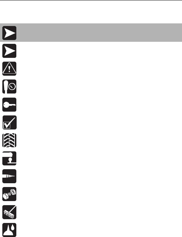
Safety Alerts
Safety Alerts
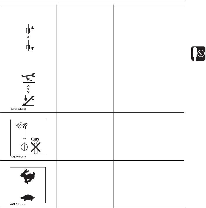
 Turning shaft will kill you or crush arm or leg. Stay away.
 Electric shock. Contacting electric lines will cause death or serious injury. Know location of lines and stay away.
 Deadly gases. Lack of oxygen or presence of gas will cause sickness or death. Provide ventilation.
 Moving tools will kill or injure. Shut off drill string power when anyone can be struck by moving or thrown tools. Never use pipe wrenches on drill string.
 Jobsite hazards could cause death or serious injury. Use correct equipment and work methods. Use and maintain proper safety equipment.
 Crushing weight could cause death or serious injury. Use proper procedures and equipment or stay away.
 Moving parts could cut off hand or foot. Stay away.
CMW
JT922 Operator’s Manual
Safety Alerts
Safety - 15
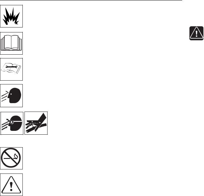
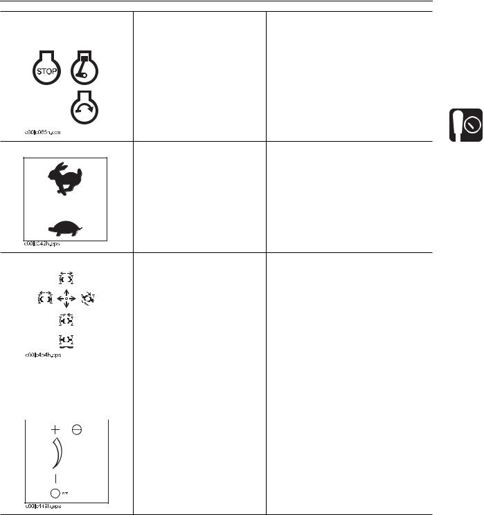
 Explosion possible. Serious injury or equipment damage could occur. Follow directions carefully.
 Incorrect procedures could result in death, injury, or property damage. Learn to use equipment correctly.
 Improper control function could cause death or serious injury. If control does not work as described in instructions, stop machine and have it serviced.
 Looking into fiber optic cable could result in permanent vision damage. Do not look into ends of fiber optic or unidentified cable.
 Pressurized fluid or air could pierce skin and cause injury or death. Stay away.
 Fire or explosion possible. Fumes could ignite and cause burns. No smoking, no flame, no spark.
 Moving traffic - hazardous situation. Death or serious injury could result. Avoid moving vehicles, wear high visibility clothing, post appropriate warning signs.
CMW

Safety - 16
JT922 Operator’s Manual
Safety Alerts
 Hot pressurized cooling system fluid could cause serious burns. Allow to cool before servicing.
 Flying objects may cause injury. Wear hard hat and safety glasses.
 Hot parts may cause burns. Do not touch until cool.
 Exposure to high noise levels may cause hearing loss. Wear hearing protection.
 Fall possible. Slips or trips may result in injury. Keep area clean.
 Battery acid may cause burns. Avoid contact.
 Improper handling or use of chemicals may result in illness, injury, or equipment damage. Follow instructions on labels and in material safety data sheets (MSDS).
CMW

JT922 Operator’s Manual
Emergency Procedures
Emergency Procedures
Safety - 17
 Jobsite hazards could cause death or serious injury. Use correct equipment and work methods. Use and maintain proper safety equipment.
Before operating any equipment, review emergency procedures and check that all safety precautions have been taken.
EMERGENCY SHUTDOWN - Turn ignition switch to stop position or push remote engine stop button (if equipped).
Electric Strike Description
 Electric shock. Contacting electric lines will cause death or serious injury. Know location of lines and stay away.
When working near electric cables, remember the following:
•Electricity follows all paths to ground, not just path of least resistance.
•Pipes, hoses, and cables will conduct electricity back to all equipment.
•Low voltage current can injure or kill. Many work-related electrocutions result from contact with less than 440 volts.
Most electric strikes are not noticeable, but indications of a strike include:
•power outage
•smoke
•explosion
•popping noises
•arcing electricity
If any of these occur, or if strike alarm sounds or flashes, assume an electric strike has occurred.
CMW

Safety - 18
JT922 Operator’s Manual
Emergency Procedures
If an Electric Line is Damaged
If you suspect an electric line has been damaged and you are on drilling unit or bonded equipment, DO NOT MOVE. Remain on drilling machine or mats and take the following actions. The order and degree of action will depend on the situation.
•Warn people nearby that an electric strike has occurred.
•Have someone contact electric company.
•Reverse drilling direction and try to break contact. Do not touch drill pipe with hands or hand-held tools.
•Press electric strike system status button.
•If alarm sounds again, stay where you are and wait for electric company to shut off power.
•If alarm does not sound and there is no other indication of a strike, wait at least one full minute before moving away from equipment. Utility might use automatic reclosers which will restart current flow. If alarm sounds again while waiting, stay where you are until electric company shuts off power.
•If alarm does not sound but all lights in strike indicator are on, assume strike is continuing and stay where you are until electric company shuts off power.
•Do not resume drilling or allow anyone into area until given permission by electric company.
If you suspect an electric line has been damaged and you are off drilling unit or bonded equipment, DO NOT TOUCH ANY EQUIPMENT connected to drilling unit. Take the following actions. The order and degree of action will depend on the situation.
•Stay where you are unless you are wearing electric insulating boots. If you leave, do not return to area or allow anyone into area until given permission by electric company.
CMW
JT922 Operator’s Manual |
Safety - 19 |
Emergency Procedures
If a Gas Line is Damaged
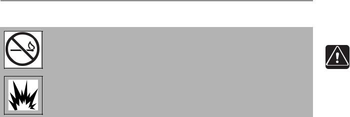
 Fire or explosion possible. Fumes could ignite and cause burns. No smoking, no flame, no spark.
 Explosion possible. Serious injury or equipment damage could occur. Follow directions carefully.
If you suspect a gas line has been damaged, take the following actions. The order and degree of action will depend on the situation.
•Immediately shut off engine(s), if this can be done safely and quickly.
•Remove any ignition source(s), if this can be done safely and quickly.
•Warn others that a gas line has been cut and that they should leave the area.
•Leave jobsite as quickly as possible.
•Immediately call your local emergency phone number and utility company.
•If jobsite is along street, stop traffic from driving near jobsite.
•Do not return to jobsite until given permission by emergency personnel and utility company.
CMW
Safety - 20
JT922 Operator’s Manual
Emergency Procedures
If a Fiber Optic Cable is Damaged
Do not look into cut ends of fiber optic or unidentified cable. Vision damage can occur.
If Machine Catches on Fire
Perform emergency shutdown procedure and then take the following actions. The order and degree of action will depend on the situation.
•Immediately move battery disconnect switch (if equipped) to disconnect position.
•If fire is small and fire extinguisher is available, attempt to extinguish fire.
•If fire cannot be extinguished, leave area as quickly as possible and contact emergency personnel.
CMW

JT922 Operator’s Manual |
Controls - 21 |
Controls
Chapter Contents
Set-Up Console . . . . . . . . . . . . . . . . . . . . . . . . . . . 22
Left Control Console . . . . . . . . . . . . . . . . . . . . . . . 24
Gauge Cluster . . . . . . . . . . . . . . . . . . . . . . . . . . . . 26
Right Control Console . . . . . . . . . . . . . . . . . . . . . . 30
Anchoring System Console . . . . . . . . . . . . . . . . . 31
Seat/Armrest . . . . . . . . . . . . . . . . . . . . . . . . . . . . . . 33
Battery . . . . . . . . . . . . . . . . . . . . . . . . . . . . . . . . . . . 34
ESID . . . . . . . . . . . . . . . . . . . . . . . . . . . . . . . . . . . . . 35
750/752 Display . . . . . . . . . . . . . . . . . . . . . . . . . . . 38
• |
Indicators . . . . . . . . . . . . . . . . . . . . . . . . . . . . . . . . . . . . . . . . . . . . . . . |
38 |
• |
Controls . . . . . . . . . . . . . . . . . . . . . . . . . . . . . . . . . . . . . . . . . . . . . . . . |
41 |
CMW
Controls - 22
JT922 Operator’s Manual
Set-Up Console
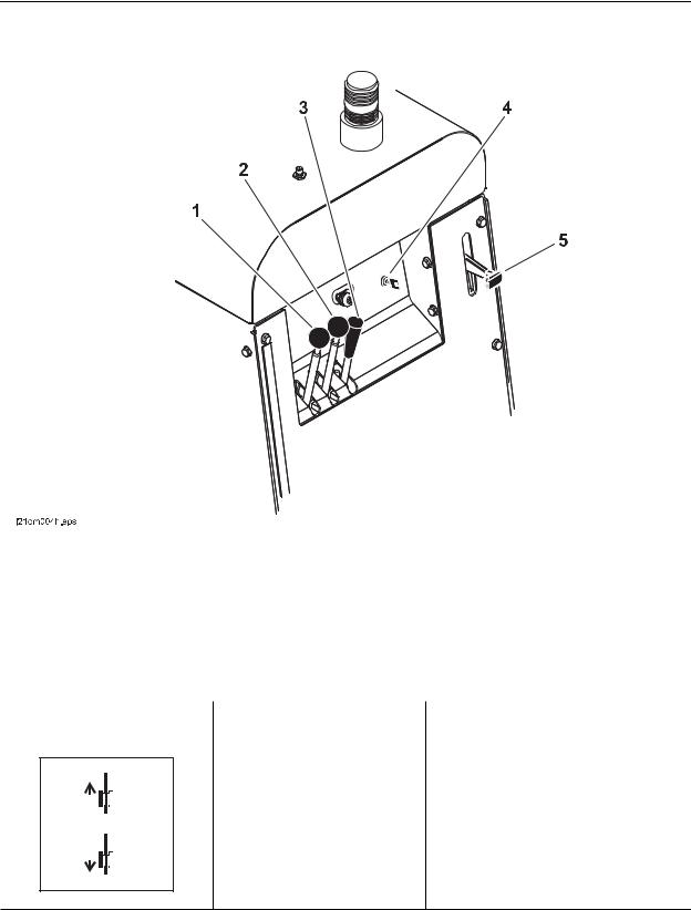
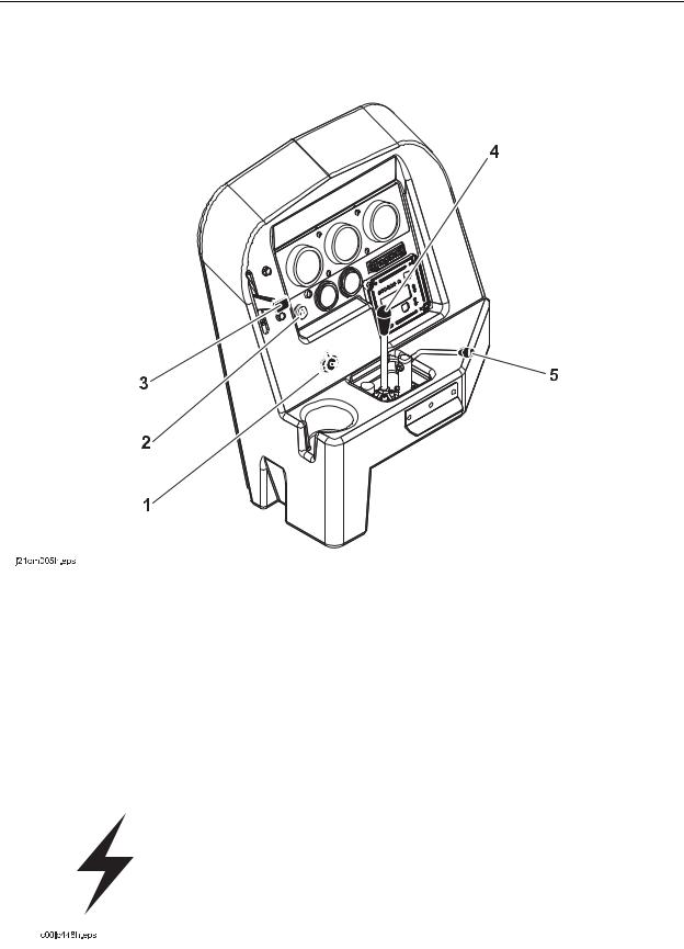
Set-Up Console
1. |
left track control |
4. |
Tracker control key |
2. |
Right track control |
5. |
Engine throttle control |
3. |
Stabilizer and frame tilt control |
|
|
|
|
|
|
Item |
Description |
Notes |
|
|
|
|
|
1. |
Left track control |
To move forward, push. |
|
To move backward, pull.
To stop, move to center.
c00ic147h.eps
CMW
JT922 Operator’s Manual
Set-Up Console
Controls - 23
Item |
Description |
Notes |
|||
|
|
|
|
|
|
2. Right track control |
To move forward, push. |
|
|||
|
|
|
|
To move backward, pull. |
|
|
|
|
|
|
|
|
|
|
|
To stop, move to center. |
|
|
|
|
|
|
|
|
|
|
|
|
|
|
|
|
|
|
|
|
c00ic148h.eps |
|
|
|||||
|
|
|
|
|
|
|
|
|
3. Stabilizer and frame tilt |
To raise stabilizer and |
Note: Stabilizer control lowers the |
||||||
control |
increase frame tilt, push. |
front of the drill frame along with the |
||||||
|
|
|
|
|
|
|
To lower stabilizer and |
stabilizer. |
|
|
|
|
|
|
|
||
|
|
|
|
|
|
|
||
|
|
|
|
|
|
|
|
|
|
|
|
|
|
|
|
decrease frame tilt, pull. |
|
|
|
|
|
|
|
|
|
|
|
|
|
|
|
|
|
|
|
|
|
|
|
|
|
|
|
|
4. Tracker control key |
To allow tracker operator to |
IMPORTANT: Remove key and keep |
|
|
|
stop thrust and rotation, move |
in tracker operator’s possession. |
|
|
||
|
|
key to enable position (up). |
|
To override tracker control mode, move key to disable position (right).
5. Engine throttle control |
To increase engine speed, |
|
push up. |
|
To decrease engine speed, |
|
pull down. |
CMW
Controls - 24
JT922 Operator’s Manual
Left Control Console
Left Control Console
Drilling/Operation Controls
1. |
Auxiliary outlet |
4. |
Wrench control |
|||
2. |
Ignition switch |
5. |
Fluid flow control |
|||
3. |
Engine throttle control |
|
|
|
||
|
|
|
|
|
|
|
Item |
Description |
|
Notes |
|||
|
|
|
|
|
|
|
1. |
Auxiliary outlet |
Provides power for other |
Power output is 12V, 5A. |
|||
|
|
|
|
equipment. |
|
|
|
|
|
|
|
|
|
|
|
|
|
|
|
|
|
|
|
|
|
|
|
CMW
JT922 Operator’s Manual
Left Control Console
Controls - 25
Item |
Description |
Notes |
|
|
|
|
|
2. Ignition switch |
To start engine, insert key and |
|
|
|
|
turn clockwise. |
|
|
|
|
|
|
|
To stop engine, turn key |
|
|
|
counterclockwise. |
|
|
|
|
|
3. Engine throttle control |
To increase engine speed, |
|
push up. |
|
To decrease engine speed, |
|
pull down. |
4. |
Wrench control |
To clamp front wrench and |
|
|
|
|
shut off drilling fluid, move |
|
|
|
|
|
|
|
toward pipe box. |
|
|
|
To unclamp front wrench, |
|
|
|
move away from pipebox. |
|
|
|
To clamp and rotate rear |
|
|
|
(rotating) wrench, move |
|
|
|
|
|
|
|
toward engine compartment. |
|
|
|
To unclamp rear (rotating) |
|
|
|
wrench, move toward seat. |
|
|
|
|
5. |
Fluid flow control |
To increase flow, turn |
|
|
|
|
counterclockwise. |
|
|
|
|
To decrease flow, turn clockwise.
To stop flow, turn all the way clockwise.
CMW
Controls - 26
JT922 Operator’s Manual
Gauge Cluster
Gauge Cluster
|
|
|
|
|
|
|
|
|
|
|
|
|
|
|
|
|
|
|
|
|
|
|
|
|
|
|
|
|
|
|
|
|
|
|
|
|
|
|
|
|
|
|
|
|
|
|
|
|
|
|
|
|
|
|
|
|
|
|
|
|
|
|
|
|
|
|
|
|
|
|
|
|
|
|
|
|
|
|
|
|
|
|
|
|
|
|
|
|
|
|
|
|
|
|
|
|
|
|
|
|
|
|
|
|
|
|
|
|
|
|
|
|
|
|
|
|
|
|
|
|
|
|
|
|
|
|
|
|
|
|
|
|
|
|
|
|
|
|
|
|
|
|
|
|
|
|
|
|
|
|
|
|
|
|
|
|
|
|
|
|
|
|
|
|
|
|
|
|
|
|
|
|
|
|
|
|
|
|
|
|
|
|
|
|
|
|
|
|
|
|
|
|
|
|
|
|
|
|
|
|
|
|
|
|
|
|
|
|
|
|
|
|
|
|
|
|
|
|
|
|
|
|
|
|
|
|
|
|
|
|
|
|
|
|
|
|
|
|
|
|
|
|
|
|
|
|
|
|
|
|
|
|
|
|
|
|
|
|
|
|
|
|
|
|
|
|
|
|
|
|
|
|
|
|
|
|
|
|
|
|
|
|
|
|
|
|
|
|
|
|
|
|
|
|
|
|
|
|
|
|
|
|
|
|
|
|
|
|
|
|
|
|
|
|
|
|
|
|
|
|
|
|
|
|
|
|
|
|
|
|
|
|
|
|
|
|
|
|
|
|
|
|
|
|
|
|
|
|
|
|
|
|
|
|
|
|
|
|
|
|
|
|
|
|
|
|
|
|
|
|
|
|
|
|
|
|
|
|
|
|
|
|
|
|
|
|
|
|
|
|
|
|
|
|
|
|
|
|
|
|
|
|
|
|
|
|
|
|
|
|
|
|
|
|
|
|
|
|
|
|
|
|
|
|
|
|
|
|
|
|
|
|
|
|
|
|
|
|
|
|
|
|
|
|
|
|
|
|
|
|
|
|
|
|
|
|
|
|
|
|
|
|
|
|
|
|
|
|
|
|
|
|
|
|
|
|
|
|
|
|
|
|
|
|
|
|
|
|
|
|
|
|
|
|
|
|
|
|
|
|
|
|
|
|
|
|
|
|
|
|
|
|
|
|
|
|
|
|
|
|
|
|
|
|
|
|
|
|
|
|
|
|
|
|
|
|
|
|
|
|
|
|
|
|
|
|
|
|
|
|
|
|
|
|
|
|
|
|
|
|
|
|
|
|
|
|
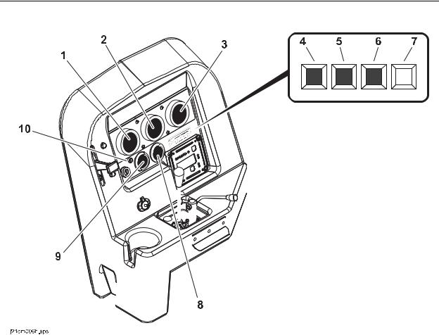
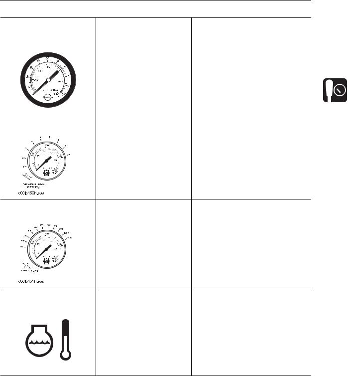
1. |
Drilling fluid pressure gauge |
6. |
Hydraulic fluid temperature indicator |
|
|
|||||||||||||||||||||
2. |
Thrust pressure gauge |
7. |
Hydraulic filter service indicator |
|
|
|||||||||||||||||||||
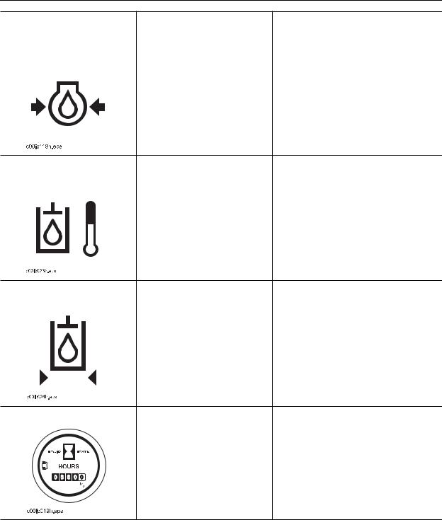
3. |
Rotation pressure gauge |
8. |
Hourmeter |
|
|
|||||||||||||||||||||
4. |
High temperature indicator |
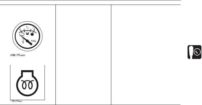
9. |
Fuel gauge |
|
|
|||||||||||||||||||||
5. |
Engine oil pressure indicator |
10. |
Cold start wait indicator |
|
|
|||||||||||||||||||||
CMW
JT922 Operator’s Manual
Gauge Cluster
Controls - 27
Item |
Description |
Notes |
||
|
|
|
|
|
1. Drilling fluid pressure |
Displays drilling fluid pressure |
|
||
gauge |
supplied by drilling fluid |
|
||
|
|
|
pump. |
|
|
|
|
|
|
|
|
|
|
|
|
c00ic157h.eps |
|
|
|
|
|
|
2. Thrust pressure gauge |
Displays hydraulic fluid |
||
|
|
|
pressure to thrust motor |
|
|
|
|
|
|
|
during thrust and pullback. |
|
|
|
Estimates thrust and pullback |
|
|
|
force on lines outside gauge. |
|
|
|
|
3. Rotation pressure |
Displays hydraulic fluid |
|
gauge |
pressure to rotation motor |
|
|
|
when spindle is turned |
|
|
|
|
|
clockwise. |
|
|
Estimates rotational torque on |
|
|
lines outside gauge. |
|
|
|
4. high temperature |
Indicates engine is |
IMPORTANT: Alarms will sound when |
|
indicator |
overheating. |
engine overheats. |
|
|
|
|
Stop engine and service unit. |
|
|
|
|
c00ic120h.eps
CMW
Controls - 28
JT922 Operator’s Manual
Gauge Cluster
Item |
Description |
Notes |
|
|
|
|
|
5. Engine oil pressure |
Indicates engine oil pressure |
IMPORTANT: Alarms will sound when |
|
indicator |
is too low. |
engine oil pressure is too low. |
|
|
|
|
Stop engine and check oil level. |
|
|
|
|
6. Hydraulic fluid |
Indicates hydraulic fluid is |
• |
Check hydraulic fluid level. |
||
temperature indicator |
overheating. |
• |
Check cooler for debris. See |
||
|
|
|
|
||
|
|
|
|
|
page 137. |
|
|
|
|
|
|
7. Hydraulic filter service |
Indicates hydraulic fluid filter |
Change filter when indicator lights |
||||||
indicator |
needs replacing. |
continuously and as indicated on |
||||||
|
|
|
|
|
|
|
|
page 142. |
|
|
|
|
|
|
|
|
|
|
|
|
|
|
|
|
|
|
|
|
|
|
|
|
|
|
|
|
|
|
|
|
|
|
|
|
8. Hourmeter |
|
|
Displays engine operating |
Use engine operating times to |
|
|
|
|
|
time. |
schedule service. |
|
|
|
|
||
|
|
|
|
|
|
|
|
|
|
|
|
|
|
|
|
|
|
CMW
JT922 Operator’s Manual
Gauge Cluster
Controls - 29
Item |
Description |
Notes |
||||||||
|
|
|
|
|
|
|
|
|
|
|
9. Fuel gauge |
Displays fuel level in tank. |
NOTICE: Use low sulfur or ultra low |
||||||||
|
|
|
|
|
|
|
|
|
|
sulfur fuel only. |
|
|
|
|
|
|
|
|
|
|
|
|
|
|
|
|
|
|
|
|
|
Refer to engine operator’s manual for |
|
|
|
|
|
|
|
|
|
|
|
|
|
|
|
|
|
|
|
|
|
|
|
|
|
|
|
|
|
|
|
|
|
|
|
|
|
|
|
|
|
|
|
cold weather fuel recommendations. |
|
|
|
|
|
|
|
|
|
|
|
|
|
|
|
|
|
|
|
|
|
Tank holds 19 gal (72 L). |
|
|
|
|
|
|
|
|
|
|
|
|
|
|
|
|
|
|
|
|
|
|
|
|
|
|
|
|
|
|
|
|
|
|
|
|
|
|
|
|
|
|
|
|
|
|
|
|
|
|
|
|
|
|
|
10. Cold start wait indicator |
Lights when intake air pre- |
|
||||||||
|
|
|
|
|
|
|
|
|
heater is operating. |
|
|
|
|
|
|
|
|
|
|
|
|
Wait until light goes off before starting engine.
CMW
Loading...