


MV800
Table of contents
 Loading...
MV800
Operator’s
Manual
CMW
®
Issue 1.0
053-2767

MV800 Operator’s Manual Overview - 1
Overview
Chapter Contents
Serial Number Location . . . . . . . . . . . . . . . . . . . . . . 2
Intended Use . . . . . . . . . . . . . . . . . . . . . . . . . . . . . . . 2
Equipment Modification . . . . . . . . . . . . . . . . . . . . . 3
Unit Components . . . . . . . . . . . . . . . . . . . . . . . . . . . 3
Operator Orientation. . . . . . . . . . . . . . . . . . . . . . . . . 4
About This Manual . . . . . . . . . . . . . . . . . . . . . . . . . . 4
• Bulleted Lists. . . . . . . . . . . . . . . . . . . . . . . . . . . . . . . . . . . . . . . . . . . . . . .4
• Numbered Lists. . . . . . . . . . . . . . . . . . . . . . . . . . . . . . . . . . . . . . . . . . . . .4
CMW
®

Overview - 2 MV800 Operator’s Manual
Serial Number Location
Serial Number Location
Record serial numbers and date of purchase in spaces provided. MV800 serial number is located as
shown.
Date of manufacture
Date of purchase
MV800 serial number (shown)
Engine serial number
Blower serial number
Water pump serial number
Trailer serial number
Intended Use
The MV800 is a self-contained vacuum excavation unit designed to remove used drilling fluid from the
jobsite and to expose existing buried utilities. The optional reverse flow system allows for spoils transfer to
another tank. The MV800 is intended for operation in ambient temperatures from 0° to 115°F (-18° to
46°C). Use in any other way is considered contrary to the intended use.
The MV800 should be operated, serviced, and repaired only by persons familiar with its particular
characteristics and acquainted with the relevant safety procedures.
CMW
®
MV800 Operator’s Manual Overview - 3
Equipment Modification
Equipment Modification
This equipment was designed and built in accordance with applicable standards and regulations.
Modification of equipment could mean that it will no longer meet regulations and may not function properly
or in accordance with the operating instructions. Modification of equipment should only be made by
competent personnel possessing knowledge of applicable standards, regulations, equipment design
functionality/requirements and any required specialized testing.
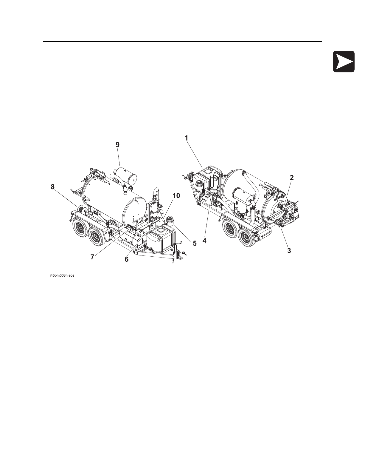
Unit Components
1. Water tank
2. Inlet valve
3. Drain/Outlet valve
4. Reverse flow valve
5. Antifreeze tank
6. Power pack
7. Operator’s station
8. Hose reel
9. Vacuum filter
10. Blower relief air filter
CMW
®
Overview - 4 MV800 Operator’s Manual
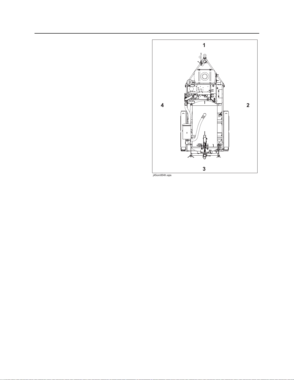
Operator Orientation
Operator Orientation
1. Front of unit
2. Right of unit
Right and left sides of machine are determined by
facing towing vehicle.
3. Rear of unit
4. Left of unit
About This Manual
This manual contains information for the proper use of this machine. See Operation Overview for basic
operating procedures. Cross references such as “See page 50” will direct you to detailed procedures.
Bulleted Lists
Bulleted lists provide helpful or important information or contain procedures that do not have to be
performed in a specific order.
Numbered Lists
Numbered lists contain illustration callouts or list steps that must be performed in order.
CMW
®

MV800 Operator’s Manual Foreword - 5
Reporting Safety Defects
Foreword
This manual is an important part of your equipment. It provides safety information and operation
®
instructions to help you use and maintain your Ditch Witch
Read this manual before using your equipment. Keep it with the equipmen t at all times for future reference.
If you sell your equipment, be sure to give this manual to the new owner.
If you need a replacement copy, contact your Ditch Witch dealer. If you need assistance in locating a
dealer, visit our website at www.ditchwitch.com or write to the following address:
The Charles Machine Works, Inc.
Attn: Marketing Department
PO Box 66
Perry, OK 73077-0066
USA
The descriptions and specifications in this manual are subject to change without notice. The Charles
Machine Works, Inc. reserves the right to improve equipment. Some product improvements may have
taken place after this manual was publishe d. For the latest information on Ditch Witch equipment, see your
Ditch Witch dealer.
equipment.
Thank you for buying and using Ditch Witch equipment.
Reporting Safety Defects
If you believe that your vehicle has a defect which could cau se a cr ash o r co uld ca use injury or death, you
should immediately inform the National Highway Traffic Safety Administration (NHTSA) in addition to
notifying the Product Safety Coordinator at The Charles Machine Works, Inc.
If NHTSA receives similar complaints, it may open an investigation, and if it finds that a safety defect exists
in a group of vehicles, it may order a recall and remedy campaign. However, NHTSA cannot become
involved in any individual problems between you, your Ditch Witch dealer, or The Charles Machine Works,
Inc.
To contact NHTSA you may either call the Auto Safety Hotline toll-free at 1-888-327-4236 (TTY: 1-800424-9153), go to http://www.safercar.gov, or write to:
Administrator
NHTSA
1200 New Jersey Avenue S.E.
Washington, DC 20590
You can also obtain other information about motor vehicle safety from http://www.safe rcar.gov.
CMW
®

Foreword - 6 MV800 Operator’s Manual
Works, Inc.
MV800
Operator’s Manual
Issue number 1.0/OM-9/14
Part number 053-2767
Copyright 2014
by The Charles Machine Works, Inc.
, Ditch Witch, and CMW are registered trademarks of The Charles Machine
U.S. patents pending.
®
CMW
MV800 Operator’s Manual Contents - 7
Content s
Overview
machine serial number, information about the type of work this machine is designed
to perform, basic machine components, and how to use this manual
Foreword
part number, revision level, and publication date of this manual, and factory contact
information
Safety
machine safety alerts and emergency procedures
Controls
machine controls, gauges, and indicators and how to use them
Operation Overview
an overview for completing a job with this machine: planning, setting up, vacuuming,
potholing, and restoring the jobsite; with cross references to detailed procedures
Prepare
procedures for inspecting and classifying the jobsite, and preparing the jobsite for
work
Transport
procedures for lifting and hauling
1
5
9
19
27
31
37
Vacuum and Pothole
procedures for removing debris and potholing utility locations
Complete the Job
procedures for restoring the jobsite and rinsing and storing equipment
Service
service intervals and instructions for this machine including lubrication, replacement
of wear items, and basic maintenance
Specifications
machine specifications including weights, measurements, power ratings, and fluid
capacities
Support
the warranty policy for this machine, and procedures for obtaining warranty
consideration and training
41
55
59
93
97
CMW
®

Contents - 8 MV800 Operator’s Manual
Service Record
a record of major service performed on the machine
Appendix
additional information about Ditch Witch® equipment
101
103
CMW
®

MV800 Operator’s Manual Safety - 9
Safety
Chapter Contents
Guidelines . . . . . . . . . . . . . . . . . . . . . . . . . . . . . . . . 10
Emergency Procedures . . . . . . . . . . . . . . . . . . . . . 11
• Electric Strike Description. . . . . . . . . . . . . . . . . . . . . . . . . . . . . . . . . . . .11
• If an Electric Line is Damaged . . . . . . . . . . . . . . . . . . . . . . . . . . . . . . . .12
• If a Gas Line is Damaged . . . . . . . . . . . . . . . . . . . . . . . . . . . . . . . . . . . .13
• If a Fiber Optic Cable is Damaged . . . . . . . . . . . . . . . . . . . . . . . . . . . . .14
• If Machine Catches on Fire. . . . . . . . . . . . . . . . . . . . . . . . . . . . . . . . . . .14
Safety Alert Classifications . . . . . . . . . . . . . . . . . . 15
Machine Safety Alerts . . . . . . . . . . . . . . . . . . . . . . 16
CMW
®

Safety - 10 MV800 Operator’s Manual
Guidelines
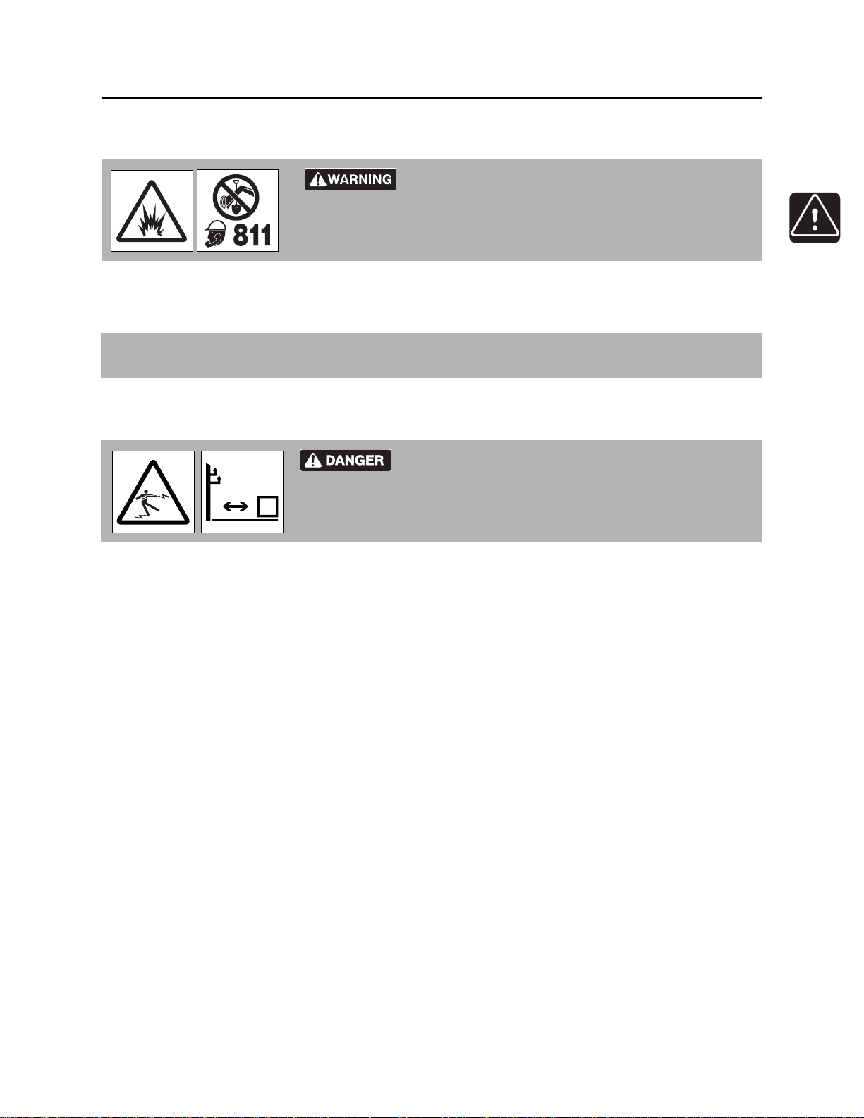
Guidelines
Follow these guidelines before operating any jobsite equipment:
• Complete proper training and read operator’s manual before using equipment.
• Contact your local One-Call (811 in USA) or the One-Call referral number (888-258-0808 in USA and
Canada) to have underground utilities located before digging. Also contact any utilities that do not
participate in the One-Call service. Mark proposed p ath with white paint prior to cont acting One- Call or
utilities.
• Classify jobsite based on its hazards and use cor rect tools and machin ery, safety equipment, and work
methods for jobsite.
• Mark jobsite clearly and keep spectators away.
• Wear personal protective equipment.
• Review jobsite hazards, safety and emergency procedures, and individual responsibilities with all
personnel before work begins. Safety videos are available from your Ditch Witch
ditchwitch.com/resources/safety .
• Replace missing or damaged safety shields and safety signs.
®
dealer or at
• Use equipment carefully. Stop operation and investigate anything that does not look or feel right.
• Do not operate unit where flammable gas may be present.
• Contact your Ditch Witch dealer if you have any question about operation, ma intenance, or equipment
use.
• Complete the equipment checklist located at www.ditchwitch.com/resources/safety.
CMW
®
MV800 Operator’s Manual Safety - 11
Emergency Procedures
Emergency Procedures
Jobsite hazards could cause death or serious injury. Use
correct equipment and work methods. Use and maintain proper safety
equipment.
Before operating any equipment, review emergency proc edures and check that all safety precau tions have
been taken.
EMERGENCY SHUTDOWN - Turn ignition switch to stop position or push remote e ngine stop button ( if
equipped).
Electric Strike Description
or serious injury. Know location of lines and stay away.
274-050
Electric shock. Contacting electric lines will cause death
When working near electric cables, remember the following:
• Electricity follows all paths to ground, not just path of least resistance.
• Pipes, hoses, and cables will conduct electricity back to all equipment.
• Low voltage current can injure or kill. Many work-related electrocutions result from contact with less
than 440 volts.
Most electric strikes are not noticeable, but indications of a strike include:
• power outage
•smoke
•explosion
• popping noises
• arcing electricity
If any of these occur, assume an electric strike has occurred.
CMW
®

Safety - 12 MV800 Operator’s Manual
Emergency Procedures
If an Electric Line is Damaged
If you suspect an electric line has been damaged and you are on truck or trailer, DO NOT MOVE.
Remain on truck or trailer and take the following actions. The order and degree of action will depend on the
situation.
• Warn people nearby that an electric strike has occurred. Instruct them to leave the area and contact
utility.
• Do not allow anyone into area until given permission by utility company.
• Do not allow anyone to touch equipment.
If you suspect an electric line has been damaged and you are off truck or trailer, DO NOT TOUCH
EQUIPMENT. Take the following actions. The order and degree of action will depend on the situation.
• LEAVE AREA. The ground surface may be electrified so take small shuffle steps with feet close
together to reduce the hazard of being shocked from one foot to the other.
• Contact utility company to shut off power.
• Do not return to area or allow anyone into area until given permission by utility company.
CMW
®
MV800 Operator’s Manual Safety - 13
Emergency Procedures
If a Gas Line is Damaged
Fire or explosion possible. Fumes could ignite and cause
burns. No smoking, no flame, no spark.
Explosion possible. Serious injury or equipment damage could occur.
Follow directions carefully.
If you suspect a gas line has been damaged, take the following actions. The order and degree of action will
depend on the situation.
• Immediately shut off engine(s), if this can be done safely and quickly.
• Remove any ignition source(s), if this can be done safely and quickly.
275-419 (2P)
• Warn others that a gas line has been cut and that they should leave the area.
• Leave jobsite as quickly as possible.
• Immediately call your local emergency phone number and utility company.
• If jobsite is along street, stop traffic from driving near jobsite.
• Do not return to jobsite until given permission by emergency personnel and utility company.
CMW
®

Safety - 14 MV800 Operator’s Manual
Emergency Procedures
If a Fiber Optic Cable is Damaged
Do not look into cut ends of fiber optic or unidentified cable. Vision damage can occur. Contact utility
company.
If Machine Catches on Fire
Perform emergency shutdown procedure and then take the following actions. The order and degree of
action will depend on the situation.
• Immediately move battery disconnect switch (if equipped and accessible) to disconnect position.
• If fire is small and fire extinguisher is available, attempt to extinguish fire.
• If fire cannot be extinguished, leave area as quickly as possible and contact emergency personnel.
CMW
®

MV800 Operator’s Manual Safety - 15
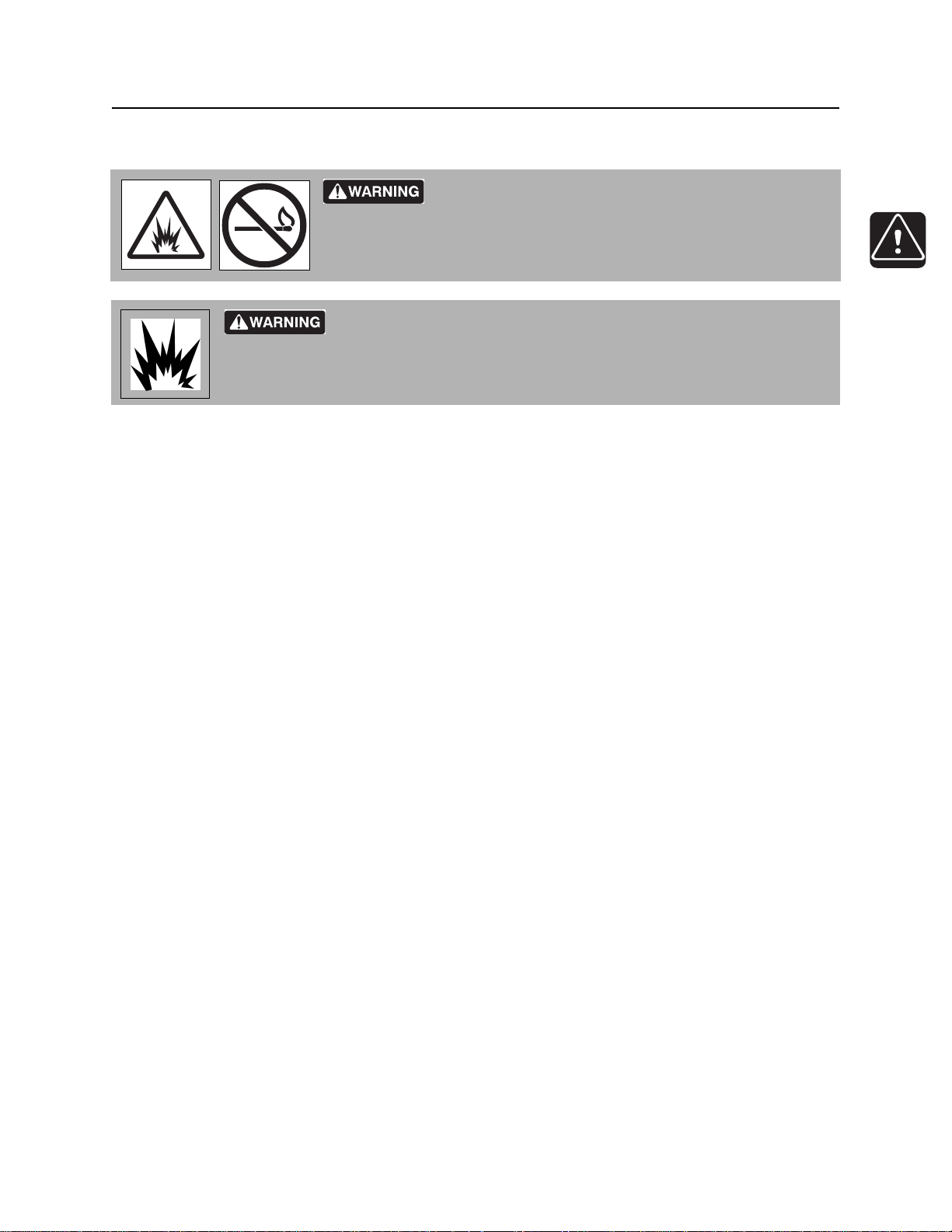
Safety Alert Classifications
Safety Alert Classifications
These classifications and the icons defined on the following pages work together to alert you to situations
which could be harmful to you, jobsite bystanders or your equipment. When you see these words and
icons in the book or on the machine, carefully read and follow all instructions. YOUR SAFETY IS AT
STAKE.
Watch for the three safety alert levels: DANGER, WARNING and CAUTION. Learn what each level
means.
indicates a hazardous situation that, if not avoided, will result in death or serious injury. This
signal word is to be limited to the most extreme situations.
indicates a hazardous situation that, if not avoided, could result in death or serious injury.
indicates a hazardous situation that, if not avoided, could result in minor or moderate injury.
Watch for two other words: NOTICE and IMPORTANT.
NOTICE indicates information considered important, but not hazard-related (e.g., messages relating to
property damage).
IMPORTANT can help you do a better job or make your job easier in some way.
CMW
®
Safety - 16 MV800 Operator’s Manual
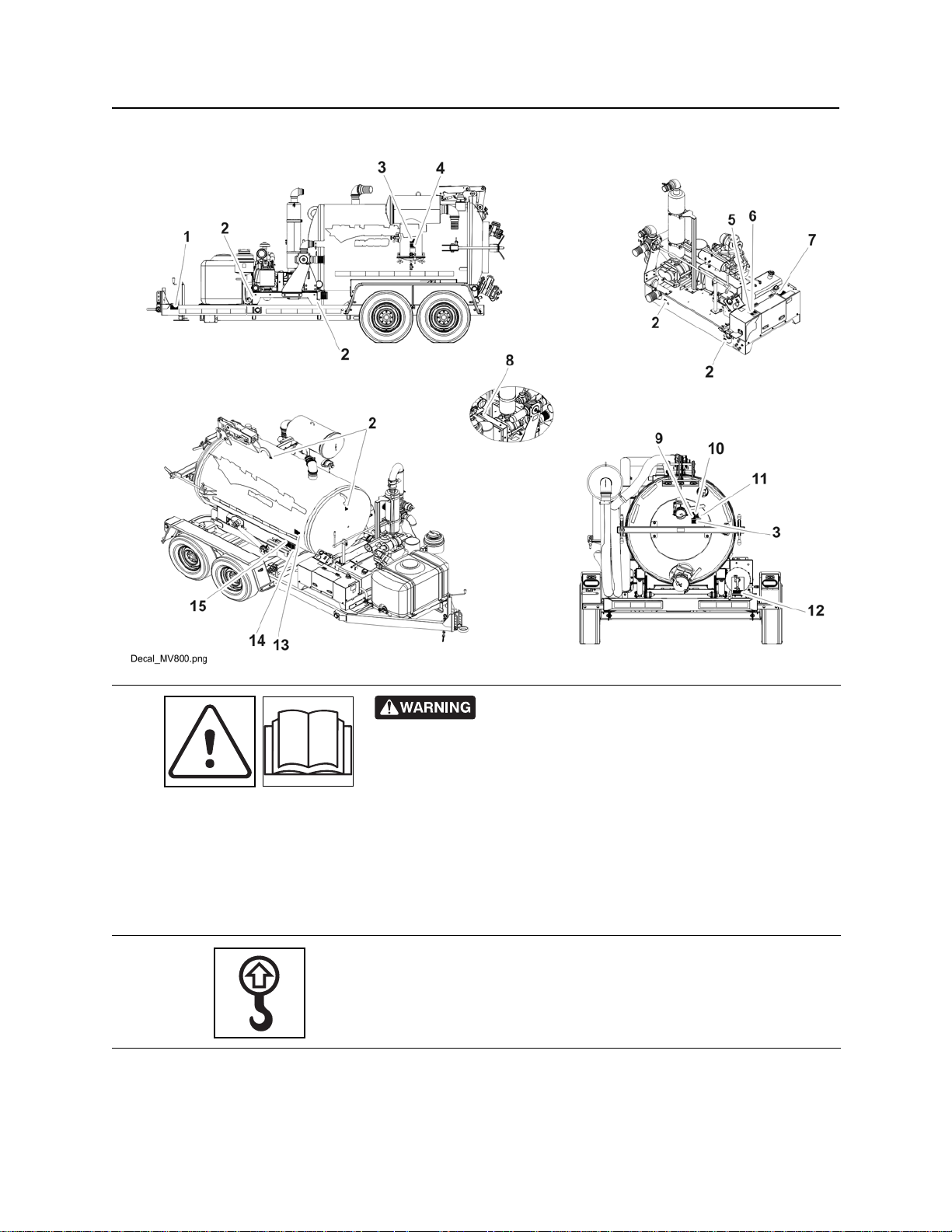
Machine Safety Alerts
Machine Safety Alerts
275-146
• Secure equipment and accessories with chain and binder.
• Check brakes and lights prior to use.
1
2
• Use proper size coupler.
• Maintain adequate distan ce for stopping and passing vehicles.
• Block wheels when parked.
• Check tire condition and inflation frequently.
• Failure to follow these rules may result in personal injury.
Lift point. See Tra nsport chapter for more information.
274-442
CMW
®
MV800 Operator’s Manual Safety - 17
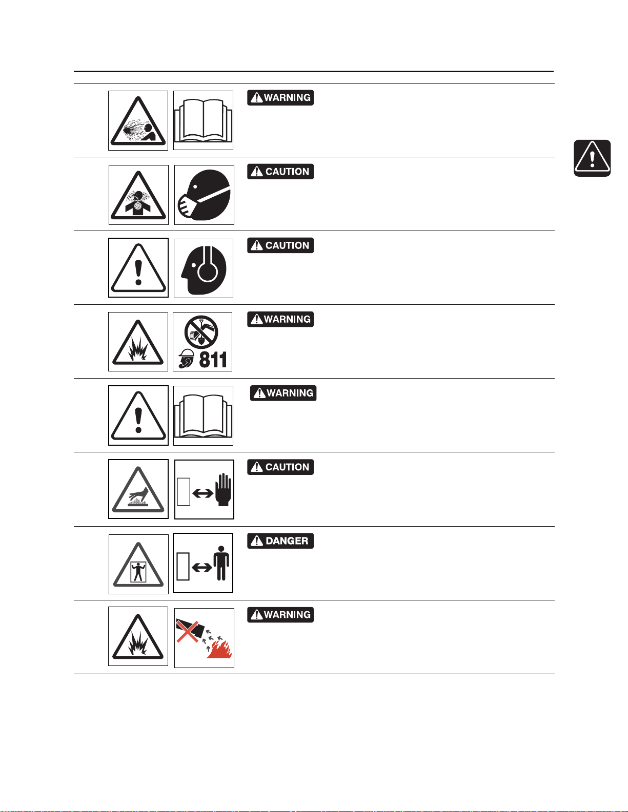
Machine Safety Alerts
Contents under pressure. Relieve pressure b efore
3
opening. Death or injury could occur.
Use breathing protection when exposed to silica
dust.
4
270-4952
Exposure to high noise levels may cause hearing
5
loss. Wear hearing protection.
Jobsite hazards could cause death or serious
6
injury. Use correct equipment and work methods. Use and maintain
proper safety equipment.
274-050; 274-724 (2P)
270-2732
700-009 (2-P)
7
8
9
10
Read operator’s manual. Know how to use all
controls. Your safety is at stake.
273-475
Hot parts may cause burns. Do not touch until cool
or wear gloves.
275-355 (2-P), 273-423 (2-P)
Confined space will cause suffocation. Use proper
procedures for entering or stay away.
273-200
Fire or explosion possible. Do not vacuum
flammable or combustible substances.
273-483
CMW
®

Safety - 18 MV800 Operator’s Manual
Machine Safety Alerts
Vacuum can suffocate. Keep hose end away from
face.
11
12
13
14
273-205
Pressurized fluid or air could pierce skin and cause
severe injury. Refer to operator’s manual for proper use.
Crushing weight could cause
death or serious injury. Stay away.
275-326
Moving parts could cut off hand or foot. Stay away.
275-184
270-6035
15
Crushing weight. Place cylinder lock on extended
cylinder and secure.
273-231, 273-413
CMW
®

MV800 Operator’s Manual Controls - 19
Controls
Chapter Contents
Engine . . . . . . . . . . . . . . . . . . . . . . . . . . . . . . . . . . . 20
Operator’s Station . . . . . . . . . . . . . . . . . . . . . . . . . 21
Machine . . . . . . . . . . . . . . . . . . . . . . . . . . . . . . . . . . 24
CMW
®
Controls - 20 MV800 Operator’s Manual
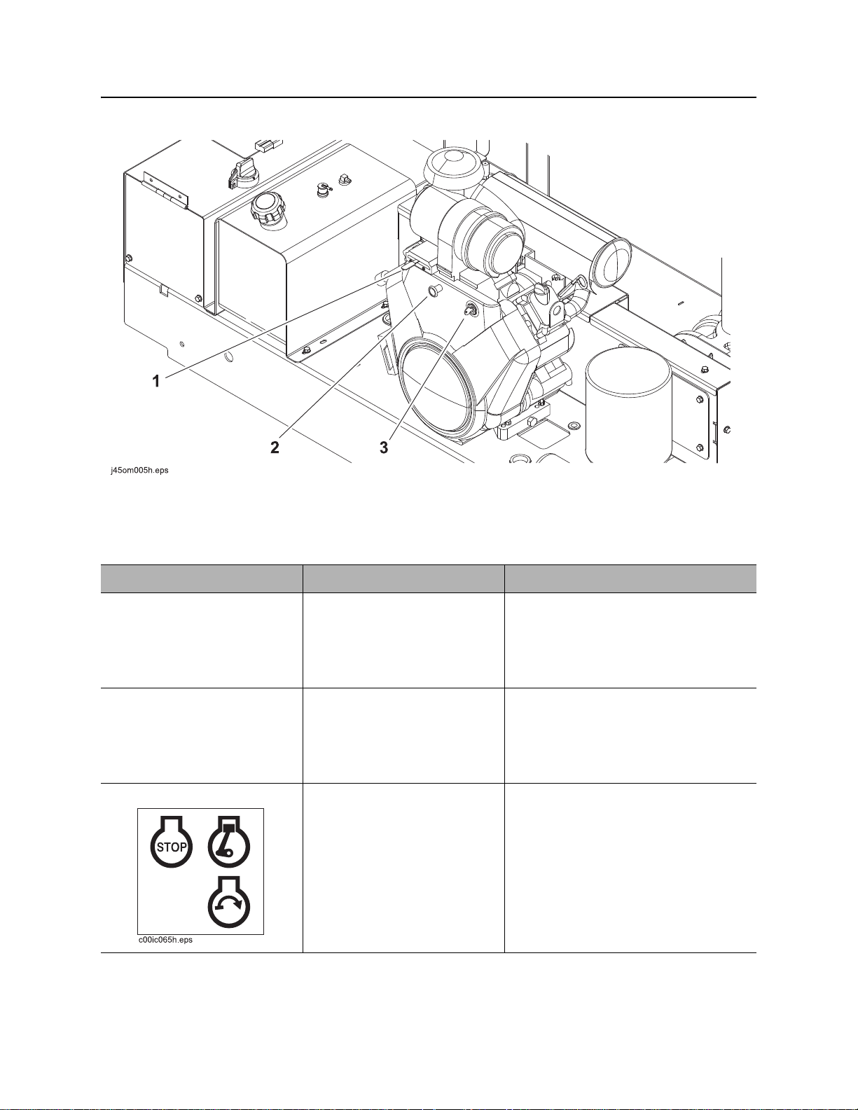
Engine
Engine
1. Throttle
2. Choke
Item Description Notes
1. Throttle To increase engine speed,
move to right.
To decrease engine speed,
move to left.
2. Choke To help start cold engine, pull
knob.
When engine has warmed,
push in completely.
3. Ignition switch T o star t engine, insert key and
turn clockwise.
To stop engine, turn key
counterclockwise.
3. Ignition switch
IMPORTANT: Run engine at full
throttle during operation.
IMPORTANT:
• When engine is on, blower
operates and vacuum is present
at tank inlet.
• All indicators should light briefly at
startup.
CMW
®

MV800 Operator’s Manual Controls - 21
c00ic114t.eps
Operator Station
Operator Station
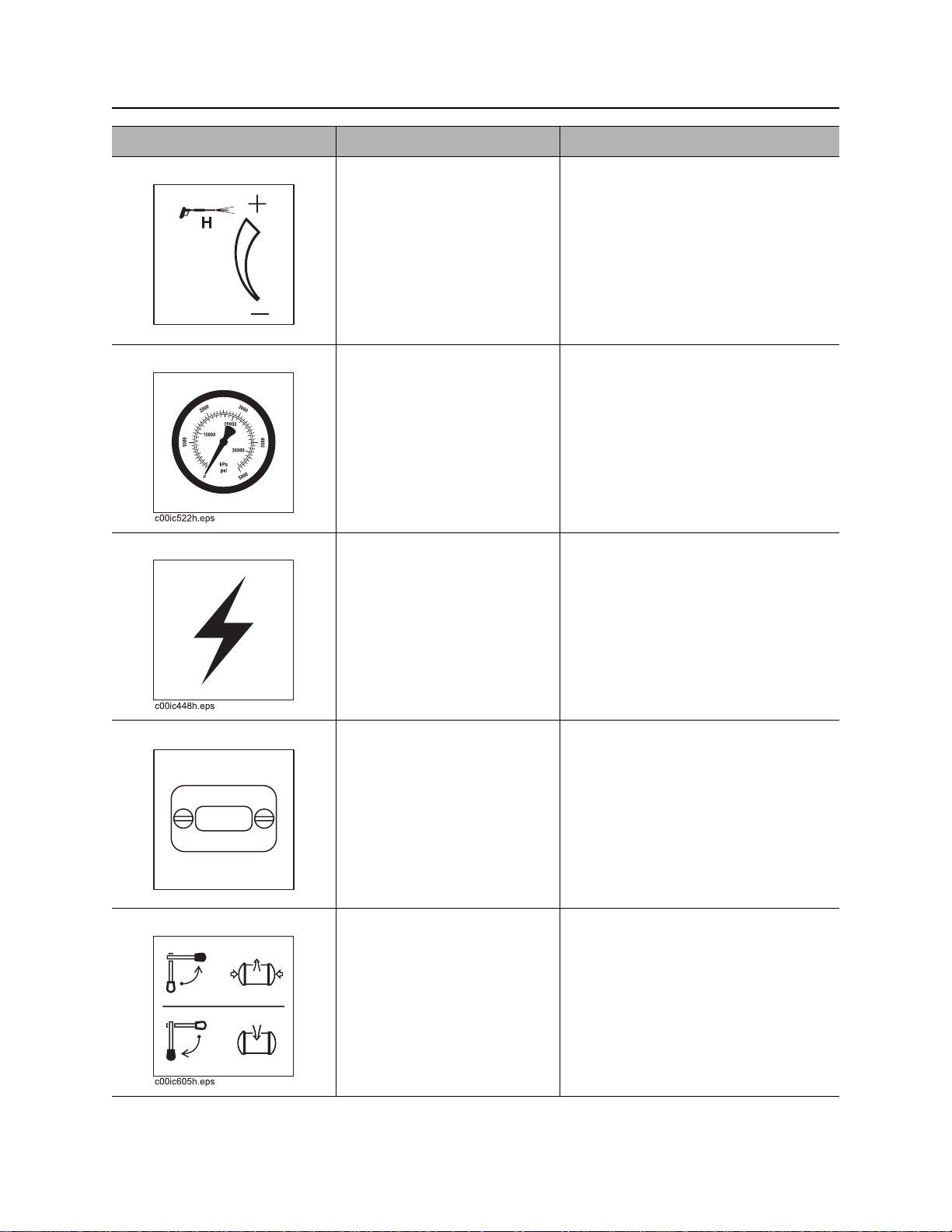
1. Water pressure switch
2. Water pressure control
3. Water pressure gauge
4. Auxiliary outlet
Item Description Notes
1. Water pressure switch To turn on water pump, press
top.
To turn off water pump, move
to center position.
To bypass low water
indication, press bottom.
Water pump will operate for
60 seconds.
5. Hourmeter
6. Flow direction control (optional)
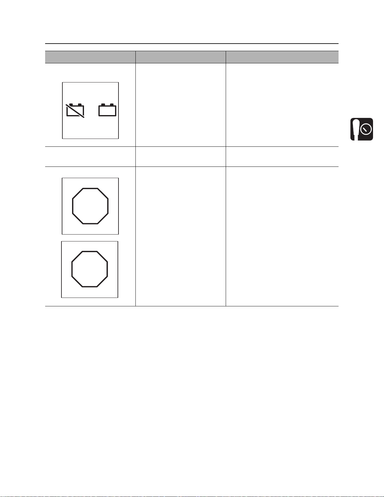
7. Battery disconnect switch
8. Tethered tank control outlet
Use bypass to feed antifreeze into
system when freshwater tank is
empty. See “Add Antifreeze” on
page 56.
CMW
®
Controls - 22 MV800 Operator’s Manual
c00ic113t.eps
c00ic112t.eps
Operator Station
Item Description Notes
2. Water pressure control To increase water pressure,
turn clockwise.
To decrease water pressure,
turn counterclockwise.
3. Water pressure gauge Displays water pressure
when water pressure switch
is on and spray wand is in
use.
4. Auxiliary outlet To operate work lights or
other 12V devices, plug into
outlet.
5. Hourmeter Displays engine operating
time.
6. Flow direction control To operate in reverse flow
mode, turn counterclockwise.
To operate in vacuum mode,
turn clockwise.
Outlet has power only when ignition
switch is on.
Hourmeter runs when engine is
running.
Use these times to schedule service.
Use optional reverse flow to unload
tank contents to another tank.
Operate in reverse flow mode only
when drain/outlet valve is open.
CMW
®
MV800 Operator’s Manual Controls - 23
c00ic063t.eps
+
_
+
_
c00ic065t.eps
DOWN
c00ic064t.eps
U P
Operator Station
Item Description Notes
7. Battery disconnect
switch
8. Tethered tank control
outlet
Tethered tank control To lift and lower tank, set
To connect, turn clockwise.
To disconnect, turn
counterclockwise.
Connection for tethered tank
control.
hydraulic function switch to
the tank position, then
• To lift tank, press UP.
• To lower tank, press
DOWN.
To open and close tank door,
set hydraulic function switch
to the door position, then
IMPORTANT: Use battery disconnect
switch when servicing, welding, and
during long-term storage.
NOTICE: When opening and closing
door, stand in a position with a full
view of the door.
• To open door, press UP.
• To close door, press
DOWN.
CMW
®
Controls - 24 MV800 Operator’s Manual
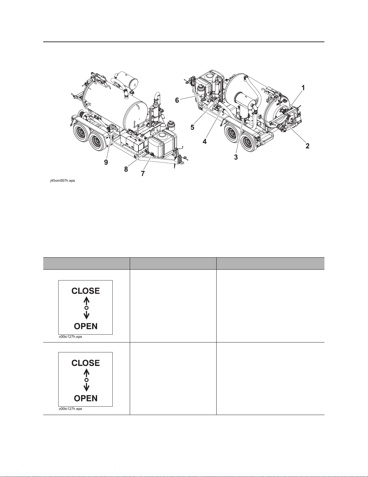
Machine
Machine
1. Inlet valve
2. Drain/Outlet valve
3. Vacuum filter drain
4. Vacuum gauge
5. Reverse flow gauge (optional)
Item Description Notes
1. Inlet valve To close valve (stop suction),
rotate up.
To open valve (start suction),
rotate down.
2. Drain/Outlet valve To drain tank, rotate down.
To close drain, rotate up.
6. Antifreeze tank supply valve (optional)
7. Water tank drain (optional)
8. Water tank supply valve (optional)
9. Hydraulic function switch (optional)
NOTICE: Do not idle engine with inlet
valve closed.
CMW
®
MV800 Operator’s Manual Controls - 25
c00ic602h.eps
c00ic604h.eps
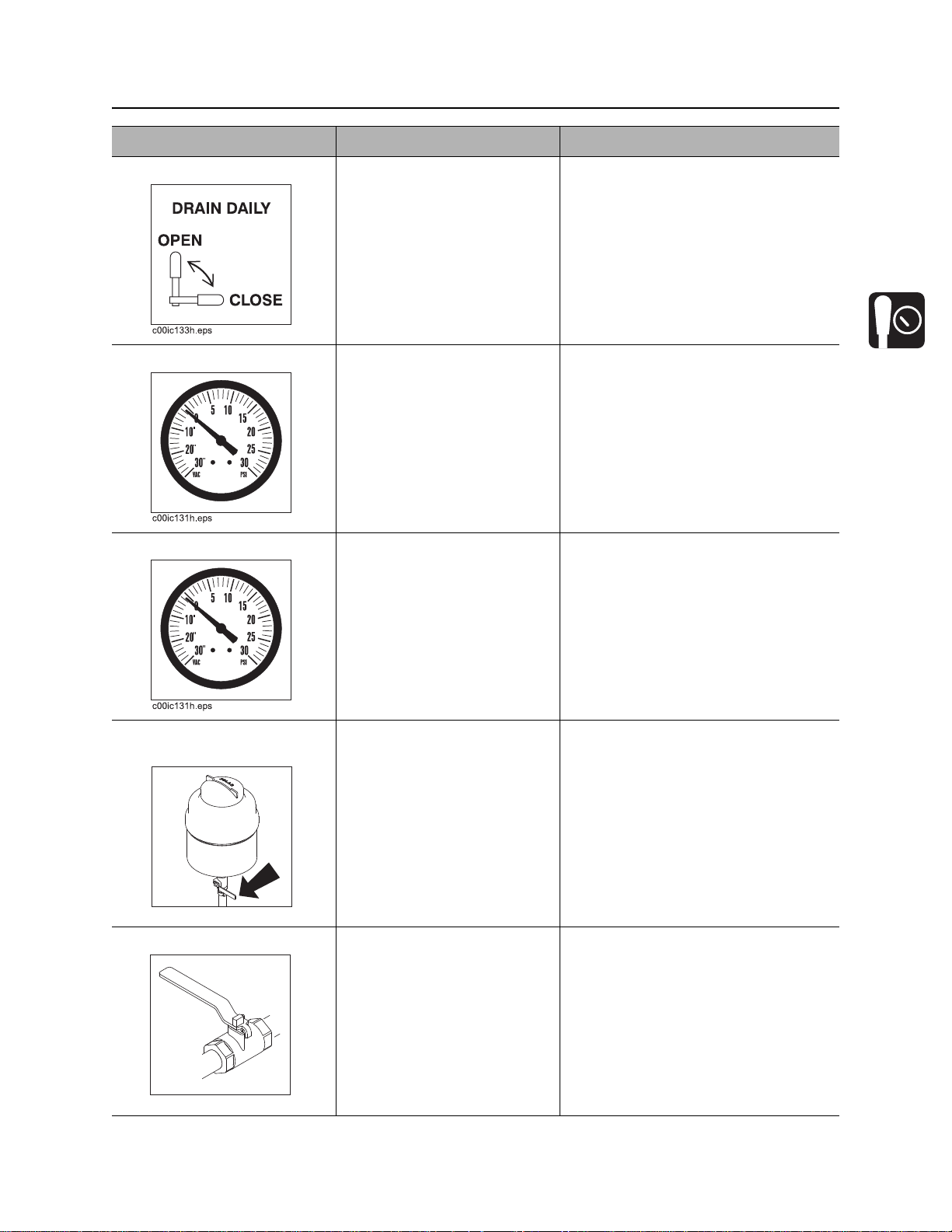
Machine
Item Description Notes
3. Vacuum filter drain To drain vacuum filter
canister, rotate up.
To close drain, rotate down.
4. Vacuum gauge Displays blower vacuum
reading in inches of mercury.
Vacuum relief valve opens
when vacuum reaches 15”
(381 mm).
5. Reverse flow gauge Displays reverse flow
pressure.
6. Antifreeze tank supply
valve
To open valve (send
antifreeze through pump and
water lance), rotate
counterclockwise.
To close valve (stop
antifreeze flow), rotate
clockwise.
7. Water tank drain To drain tank, open valve.
Close valve when tank is
empty.
IMPORTANT: Water tank supply
valve or antifreeze supply valve must
be open when pump is running or
pump will be damaged.
CMW
®
Controls - 26 MV800 Operator’s Manual
c00ic603h.eps
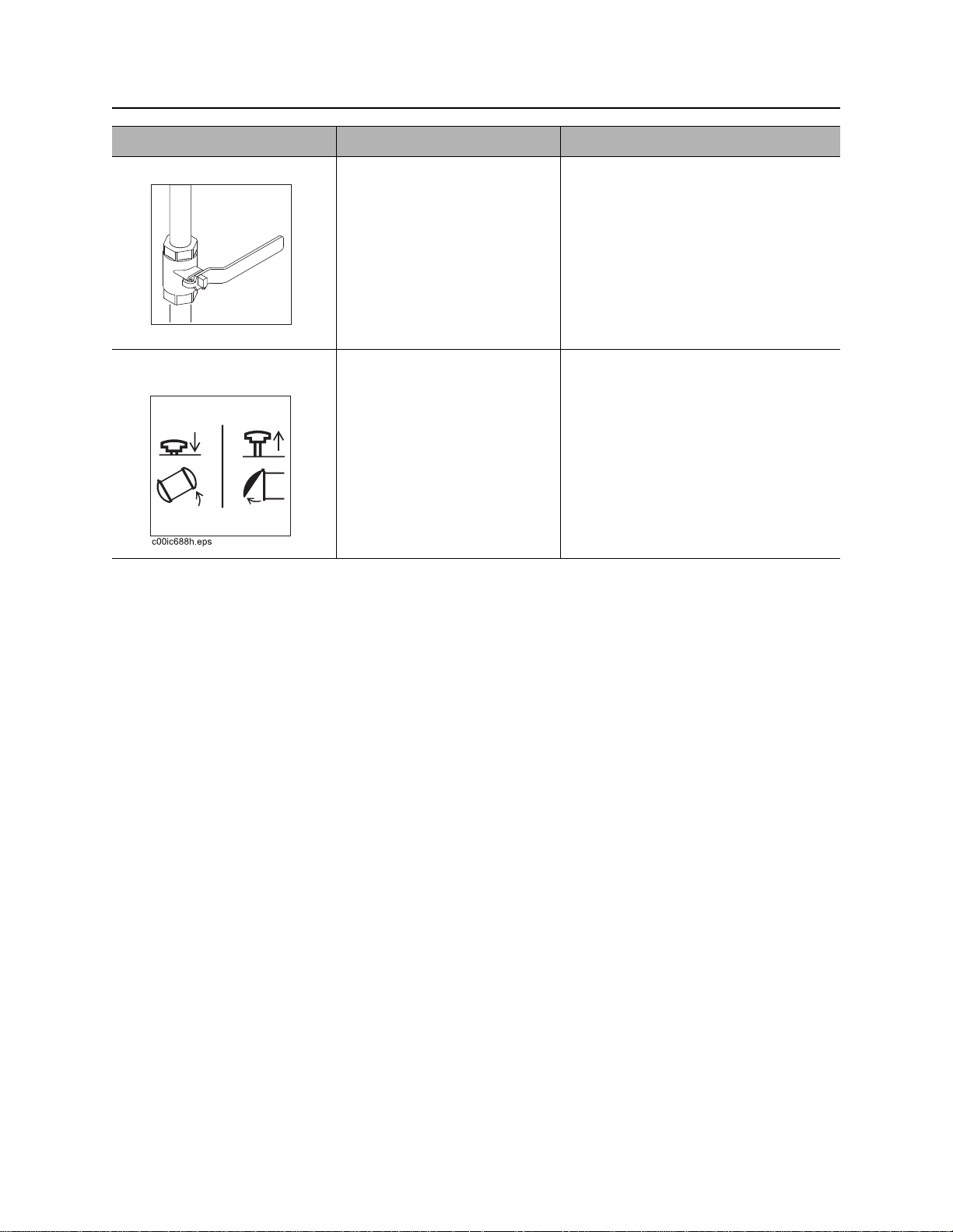
Machine
Item Description Notes
8. Water t ank supply valve To open valve (send water
from the water tank through
the pump and water lance),
rotate counterclockwise.
To close valve (stop water
flow), rotate clockwise.
9. Hydraulic function
switch
To lift and lower tank, push
down.
To open and close door, pull
up.
IMPORTANT: Water tank supply
valve or antifreeze supply valve must
be open when pump is running or
pump will be damaged.
Only with hydraulic door option.
CMW
®

MV800 Operator’s Manual Operation Overview - 27
Operation Overview
Chapter Contents
Planning . . . . . . . . . . . . . . . . . . . . . . . . . . . . . . . . . 28
Setting Up at Jobsite . . . . . . . . . . . . . . . . . . . . . . . 28
Vacuuming . . . . . . . . . . . . . . . . . . . . . . . . . . . . . . . 28
Potholing . . . . . . . . . . . . . . . . . . . . . . . . . . . . . . . . 29
Leaving Jobsite . . . . . . . . . . . . . . . . . . . . . . . . . . . 29
Storing Equipment . . . . . . . . . . . . . . . . . . . . . . . . . 29
CMW
®

Operation Overview - 28 MV800 Operator’s Manual
Planning
Planning
1. Gather information about jobsite (page 32).
2. Inspect jobsite (page 33).
3. Check supplies and prepare equipment (page 35).
Setting Up at Jobsite
1. Prepare jobsite (page 34).
2. Leave unit hitched to towing vehicle or properly stabilized if trailer-mounted unit.
3. Block trailer wheels if trailer-mounted unit.
Vacuuming
1. Connect hoses (page 42).
2. Start unit (page 44).
3. Remove debris (page 45).
4. Disconnect hoses.
5. Drain tank (page 48) or unload to another tank (page 50).
CMW
®

MV800 Operator’s Manual Operation Overview - 29
Potholing
Potholing
1. Connect hoses (page 42).
2. Start unit (page 42).
3. Pothole (page 46).
4. Disconnect hoses.
5. Drain tank (page 48).
Leaving Jobsite
1. Rinse unit and tools (page 57).
2. Stow tools (page 57).
Storing Equipment
1. For cold weather storage, antifreeze vacuum excavation unit (page 56).
2. For long-term storage, disconnect battery disconnect switch (page 22).
CMW
®
Loading...