

Page 1

R150/R230/R300
Operator’s
Manual
CMW
®
Issue 1.6
053- 1173
Page 2

R150/R230/R300 Operator’s Manual Overview - 1
Overview
Chapter Contents
Serial Number Location . . . . . . . . . . . . . . . . . . . . . . 2
Intended Use . . . . . . . . . . . . . . . . . . . . . . . . . . . . . . . 3
Equipment Modification . . . . . . . . . . . . . . . . . . . . . 3
Unit Components . . . . . . . . . . . . . . . . . . . . . . . . . . . 4
Operator Orientation. . . . . . . . . . . . . . . . . . . . . . . . . 4
About This Manual . . . . . . . . . . . . . . . . . . . . . . . . . . 4
• Bulleted Lists. . . . . . . . . . . . . . . . . . . . . . . . . . . . . . . . . . . . . . . . . . . . . . .5
• Numbered Lists. . . . . . . . . . . . . . . . . . . . . . . . . . . . . . . . . . . . . . . . . . . . .5
• “Continued” Indicators . . . . . . . . . . . . . . . . . . . . . . . . . . . . . . . . . . . . . . .5
CMW
Page 3
Overview - 2 R150/R230/R300 Operator’s Manual
Serial Number Location
Serial Number Location
Record serial numbers and date of purchase in spaces provided. Power unit serial number is located as
shown.
Date of manufacture
Date of purchase
Power unit serial number
Front end serial numbers
CMW
Page 4

R150/R230/R300 Operator’s Manual Overview - 3
Intended Use
Intended Use
The Zahn line consists of three versatile performers. The R150 is configured as a dedicated trencher. The
R230 and R300 units can be configured as dedicated trenchers or they can be configured with an
InterChange connection to allow them to accept a variety of front ends. Available interchangeable front
ends include a trencher, vibratory plow, dumper, tool carrier, backhoe, stump grinder and tiller. Contact
your Ditch Witch dealer for a complete list of available front ends.
The unit is designed for operation in temperatures typically experienced in earth moving and construction
work environments. Provisions may be required to operate in extreme temperatures. Contact your Ditch
Witch dealer.
Zahn R150, R230 and R300 units should be used with genuine Ditch Witch front ends, attachments and
components. They should be operated, serviced, and repaired only by persons familiar with their particular
characteristics and acquainted with the relevant safety procedures.
Use in any other way is considered contrary to the intended use.
Equipment Modification
This equipment was designed and built in accordance with applicable standards and regulations.
Modification of equipment could mean that it will no longer meet regulations and may not function properly
or in accordance with the operating instructions. Modification of equipment should only be made by
competent personnel possessing knowledge of applicable standards, regulations, equipment design
functionality/requirements and any required specialized testing.
CMW
Page 5
Overview - 4 R150/R230/R300 Operator’s Manual
Unit Components
Unit Components
1. operator platform
2. engine compartment
3. control console
Operator Orientation
1. Front of unit
2. Right of unit
Right and left sides of machine are determined by
facing front of unit while standing on platform.
NOTICE: Operate unit only while standing on
platform.
3. Rear of unit
4. Left of unit
4. front end manifold
5. articulation joint
6. InterChange connection (R230 and R300)
CMW
Page 6

R150/R230/R300 Operator’s Manual Overview - 5
About This Manual
About This Manual
This manual contains information for the proper use of this machine. See Operation Overview for basic
operating procedures. Cross references such as “See page 50” will direct you to detailed procedures.
Bulleted Lists
Bulleted lists provide helpful or important information or contain procedure s that do not have to be
performed in a specific order.
Numbered Lists
Numbered lists contain illustration callouts or list steps that must be performed in order.
“Continued” Indicators
indicates that a procedure is continued on the next page.
CMW
Page 7

Overview - 6 R150/R230/R300 Operator’s Manual
About This Manual
CMW
Page 8

R150/R230/R300 Operator’s Manual Foreword - 7
Foreword
This manual is an important part of your equipment. It provides safety information and operation
instructions to help you use and maintain your Ditch Witch equipment.
Read this manual before using your equipment. Keep it with the equipmen t at all times for future reference.
If you sell your equipment, be sure to give this manual to the new owner.
If you need a replacement copy, contact your Ditch Witch dealer or download it at www.ditchwitch.com. If
you need assistance in locating a dealer, visit our website or write to the following address:
The Charles Machine Works, Inc.
Attn: Marketing Department
PO Box 66
Perry, OK 73077-0066
USA
The descriptions and specifications in this manual are subject to change without notice. The Charles
Machine Works, Inc. reserves the right to improve equipment. Some product improvements may have
taken place after this manual was publishe d. For the latest information on Ditch Witch equipment, see your
Ditch Witch dealer.
Thank you for buying and using Ditch Witch equipment.
CMW
Page 9

Foreword - 8 R150/R230/R300 Operator’s Manual
R150/R230/R300
Operator’s Manual
Issue number 1.6/OM-9/09
Part number 053-1173
Copyright 2007, 2008, 2009
by The Charles Machine Works, Inc.
, Ditch Witch, CMW, AutoCrowd, Jet Trac, Roto Witch, Subsite, Fluid Miser,
Power Pipe, Super Witch, Pierce Airrow, The Underground, The Underground Authority Worldwide, and
Zahn are registered trademarks of The Ch ar les Mac hin e Works, Inc.
This product is covered by the following patent: U.S. 7,621,366; other U.S. and foreign patents pending.
CMW
Page 10

R150/R230/R300 Operator’s Manual Contents - 9
Content s
Overview
machine serial number, information about the type of work this machine is designed
to perform, basic machine components, and how to use this manual
Foreword
part number, revision level, and publication date of this manual, and factory contact
information
Safety
machine safety alerts and emergency procedures
Controls
machine controls, gauges, and indicators and how to use them
Prepare
procedures for inspecting and classifying the jobsite, plan ning the installation p ath (if
needed), preparing the jobsite for work, and connecting front ends
Drive
procedures for startup, cold start, driving, and shutdown
Transport
procedures for lifting, hauling, and towing
1
7
11
21
33
39
43
Trench
procedures for trenching
Systems and Equipment
chain, teeth, sprockets, and optional equipment
Complete the Job
procedures for restoring the jobsite and rinsing and storing equipment
Service
service intervals and instructions for this machine including lubrication, replacement
of wear items, and basic maintenance
Specifications
machine specifications including weights, measurements, power ratings, and fluid
capacities
51
55
59
61
81
CMW
Page 11

Contents - 10 R150/R230/R300 Operator’s Manual
Support
the warranty policy for this machine, and procedures for obtaining warranty
consideration and training
Service Record
a record of major service performed on the machine
99
103
CMW
Page 12

R150/R230/R300 Operator’s Manual Safety - 11
Safety
Chapter Contents
Guidelines . . . . . . . . . . . . . . . . . . . . . . . . . . . . . . . . 12
Safety Alert Classifications . . . . . . . . . . . . . . . . . . 13
Safety Alerts . . . . . . . . . . . . . . . . . . . . . . . . . . . . . . 14
Emergency Procedures . . . . . . . . . . . . . . . . . . . . . 17
• Electric Strike Description . . . . . . . . . . . . . . . . . . . . . . . . . . . . . . . . . . .17
• If an Electric Line is Damaged . . . . . . . . . . . . . . . . . . . . . . . . . . . . . . . .18
• If a Gas Line is Damaged . . . . . . . . . . . . . . . . . . . . . . . . . . . . . . . . . . . .18
• If a Fiber Optic Cable is Damaged . . . . . . . . . . . . . . . . . . . . . . . . . . . . .19
• If Machine Catches on Fire . . . . . . . . . . . . . . . . . . . . . . . . . . . . . . . . . .19
CMW
Page 13

Safety - 12 R150/R230/R300 Operator’s Manual
Guidelines
Guidelines
Follow these guidelines before operating any jobsite equipment:
• Complete proper training and read operator’s manual before using equipment.
• Contact your local One-Call (811 in USA) or the One-Call referral number ( 888-258-0808 in USA and
Canada) to have underground utilities located before digging. Also contact any utilities that do not
participate in the One-Call service.
• Classify jobsite based on its hazards and use cor rect tools and machin ery, safety equipment, and work
methods for jobsite.
• Mark jobsite clearly and keep spectators away.
• Wear personal protective equipment.
• Review jobsite hazards, safety and emergency procedures, and individual responsibilities with all
personnel before work begins. Safety videos are available at www.ditchwitch.com and from Ditch
Witch dealers.
• Replace missing or damaged safety shields and safety signs.
• Use equipment carefully. Stop operation and investigate anything that does not look or feel right.
• Do not operate unit where flammable gas is present.
• Contact your Ditch Witch dealer if you have any question about operation, ma intenance, or equipment
use.
CMW
Page 14

R150/R230/R300 Operator’s Manual Safety - 13
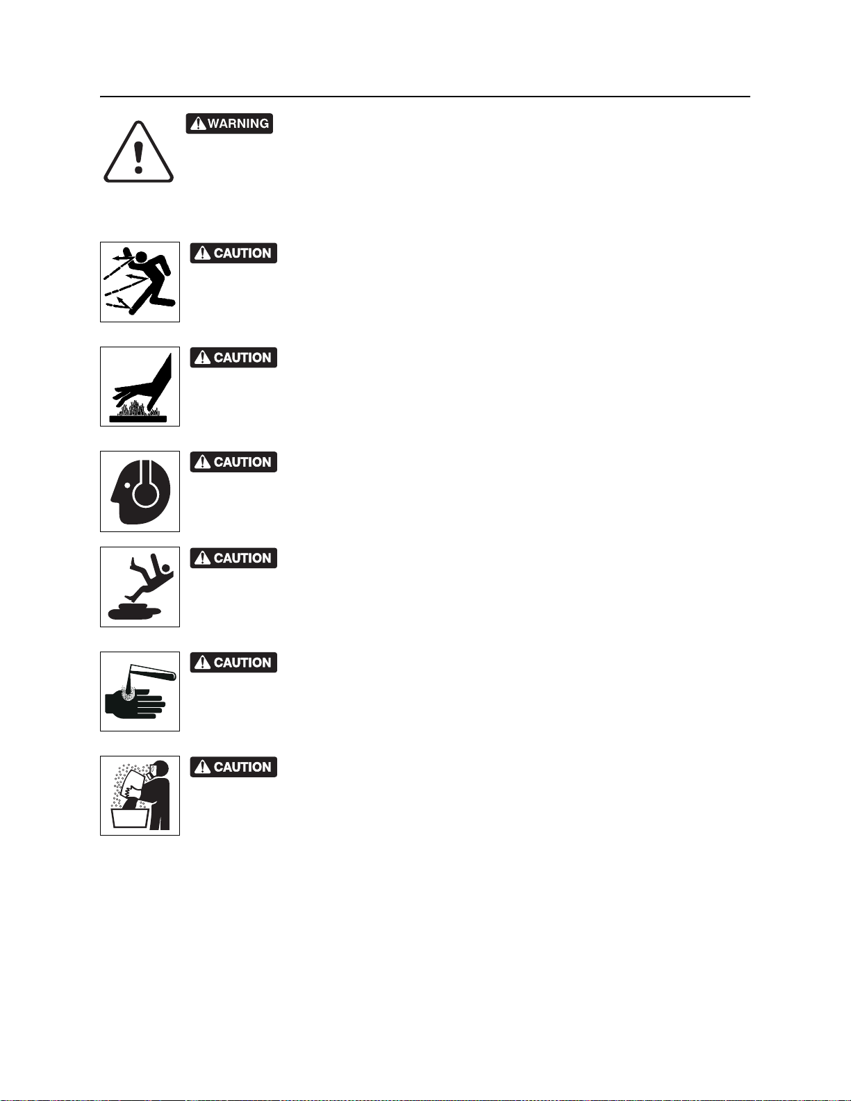
Safety Alert Classifications
Safety Alert Classifications
These classifications and the icons defined on the following pages work together to alert you to situations
which could be harmful to you, jobsite bystanders or your equipment. When you see these words and
icons in the book or on the machine, carefully read and follow all instructions. YOUR SAFETY IS AT
STAKE.
Watch for the three safety alert levels: DANGER, WARNING and CAUTION. Learn what each level
means.
indicates an imminently hazardous situation which, if not avoided, will result in death or
serious injury.
indicates a potentially hazardous situation which, if not avoided, could result in death or
serious injury.
indicates a potentially hazardous situation which, if not avoided, may result in minor or
moderate injury.
Watch for two other words: NOTICE and IMPORTANT.
NOTICE can keep you from doing something that might damage the machine or someone's property. It
can also alert you against unsafe practices.
IMPORTANT can help you do a better job or make your job easier in some way.
CMW
Page 15
Safety - 14 R150/R230/R300 Operator’s Manual
Safety Alerts
Safety Alerts
Moving digging teeth will kill you or cut off arm or leg. Stay away.
Turning shaft will kill you or crush arm or leg. Stay away.
Electric shock. Contacting electric lines will cause death or serious injury.
Know location of lines and stay away.
Deadly gases. Lack of oxygen or presence of gas will cause sickness or
death. Provide ventilation.
correct equipment and work methods. Use and maintain proper safety
equipment.
proper procedures and equipment or stay away.
Jobsite hazards could cause death or serious injury. Use
Crushing weight could cause death or seriou s injur y. Use
Moving parts could cut off hand or foot. Stay away.
CMW
Page 16
R150/R230/R300 Operator’s Manual Safety - 15
Safety Alerts
Explosion possible. Serious injury or equipment damage could occur.
Follow directions carefully .
Incorrect procedures could result in death, injury, or property damage.
Learn to use equipment correctly.
Improper control function could cause death or serious injury. If control does
not work as described in instructions, stop machine and have it serviced.
Looking into fiber optic cable could result in permanent vision damage. Do
not look into ends of fiber optic or unidentified cable.
Pressurized fluid or air could pierce skin a nd cause injur y or
death. St ay away.
Runaway possible. Machine could run over you or others. Learn how to use
all controls. Start and operate only from operator’s position.
Fire or explosion possible. Fumes could ignite and cause burns. No
smoking, no flame, no spark.
Moving traffic - hazardous situation. Death or serious injury could result.
Avoid moving vehicles, wear high visibility clothing, post appropriate warning signs.
CMW
Page 17
Safety - 16 R150/R230/R300 Operator’s Manual
Safety Alerts
Tipover possible. Machine can tip over and crush you.
• Always operate with load end uphill.
• Always carry load low. High load can cause tipping, loss of load or loss of visibility.
• Never jerk control levers. Use a steady even motion.
Flying objects may cause injury. Wear hard hat and safety glasses.
Hot parts may cause burns. Do not touch until cool.
Exposure to high noise levels may cause hearing loss. Wear hearing
protection.
Fall possible. Slips or trips may result in injury. Keep area clean.
Battery acid may cause burns. Avoid contact.
Improper handling or use of chemicals may result in illness, injury, or
equipment damage. Follow instructions on labels and in material safety data sheets
(MSDS).
CMW
Page 18

R150/R230/R300 Operator’s Manual Safety - 17
Emergency Procedures
Emergency Procedures
Before operating any equipment, review emergency proc edures and check that all safety precau tions have
been taken.
EMERGENCY SHUTDOWN: Release all controls (including cruise control pedal) and turn ignition
switch to OFF
Electric Strike Description
When working near electric cables, remember the following:
• Electricity follows all paths to ground, not just path of least resistance.
• Pipes, hoses, and cables will conduct electricity back to all equipment.
• Low voltage current can injure or kill. Almost one-third of work-related electrocutions result from
contact with less than 440 volts.
Most electric strikes are not noticeable, but indications of a strike include:
.
• power outage
•smoke
•explosion
• popping noises
• arcing electricity
If any of these occur, assume an electric strike has occurred.
CMW
Page 19

Safety - 18 R150/R230/R300 Operator’s Manual
Emergency Procedures
If an Electric Line is Damaged
If you suspect an electric line has been damaged and you are on platform, DO NOT MOVE. Remain on
platform and take the following actions. The order and degree of action will depend upon the situation.
• Warn people nearby that an electric strike has occurred. Instruct them to leave the area and contact
utility.
• Raise front end and attachments and drive from immediate area.
• Contact utility company to shut off power.
• Do not return to jobsite or allow anyone into area until given permission by utility company.
If you suspect an electric line has been damaged and you are off platform, DO NOT TOUCH UNIT. Take
the following actions. The order and degree of action will depend upon the situation.
• LEAVE AREA. The ground surface may be electrified, so take small steps with feet close together to
reduce the hazard of being shocked from one foot to the other. For more information, contact your
Ditch Witch dealer.
• Contact utility company to shut off power.
• Do not return to jobsite or allow anyone into area until given permission by utility company.
If a Gas Line is Damaged
If you suspect a gas line has been damaged, take the following actions. The order and degree of action will
depend on the situation.
• Immediately shut off engine(s), if this can be done safely and quickly.
• Remove any ignition source(s), if this can be done safely and quickly.
• Warn others that a gas line has been cut and that they should leave the area.
• Leave jobsite as quickly as possible.
• Immediately call your local emergency phone number and utility company.
• If jobsite is along street, stop traffic from driving near jobsite.
• Do not return to jobsite until given permission by emergency personnel and utility company.
CMW
Page 20

R150/R230/R300 Operator’s Manual Safety - 19
Emergency Procedures
If a Fiber Optic Cable is Damaged
Do not look into cut ends of fiber optic or unidentified cable. Vision damage can occur.
If Machine Catches on Fire
Perform emergency shutdown procedure and then take the following actions. The order and degree of
action will depend on the situation.
• Immediately move battery disconnect switch (if equipped) to disconnect position.
• If fire is small and fire extinguisher is available, attempt to extinguish fire.
• If fire cannot be extinguished, leave area as quickly as possible and contact emergency personnel.
CMW
Page 21

Safety - 20 R150/R230/R300 Operator’s Manual
Emergency Procedures
CMW
Page 22

R150/R230/R300 Operator’s Manual Controls - 21
Controls
Chapter Contents
Gauges and Indicators . . . . . . . . . . . . . . . . . . . . . 22
Controls . . . . . . . . . . . . . . . . . . . . . . . . . . . . . . . . . 24
• R150/R150E . . . . . . . . . . . . . . . . . . . . . . . . . . . . . . . . . . . . . . . . . . . . . .24
• R230/R300 . . . . . . . . . . . . . . . . . . . . . . . . . . . . . . . . . . . . . . . . . . . . . . .28
• R150/R230/R300 . . . . . . . . . . . . . . . . . . . . . . . . . . . . . . . . . . . . . . . . . .32
CMW
Page 23
Controls - 22 R150/R230/R300 Operator’s Manual
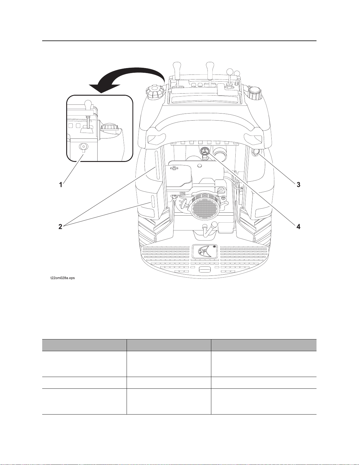
Gauges and Indicators
Gauges and Indicators
1. Auxiliary power outlet (R150E/R230/R300
only)
2. Fuel sight glass
Item Description Notes
1. Auxiliary power outlet To operate work lights or
other 12V devices, plug into
outlet.
2. Fuel tank sight window Shows level of fuel in tank.
3. Hydraulic fluid sight
glass
CMW
Shows level of hydraulic fluid
in tank. Maintain fluid at
halfway point on glass.
3. Hydraulic fluid sight glass
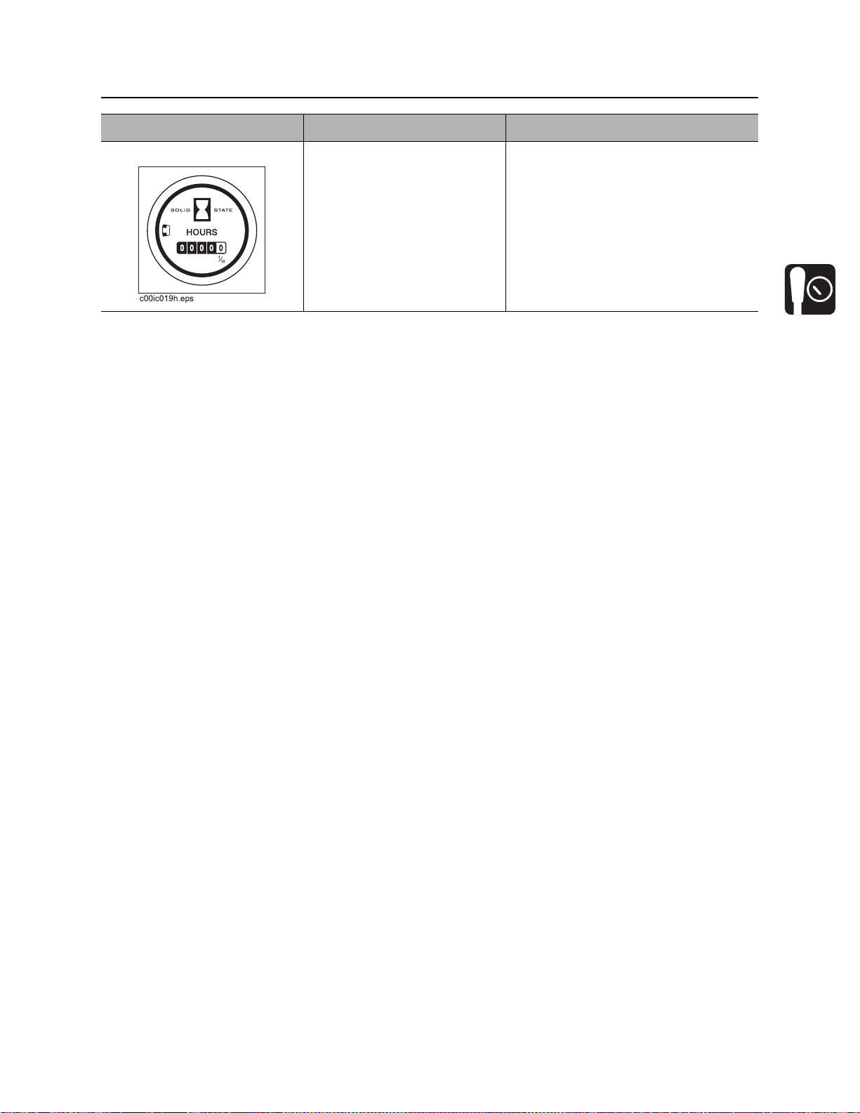
4. Hourmeter (optional)
Not available on R150 with rope start.
Page 24
R150/R230/R300 Operator’s Manual Controls - 23
Gauges and Indicators
Item Description Notes
4. Hourmeter (optional) Displays engine operating
time.
Use these times to schedule service.
CMW
Page 25
Controls - 24 R150/R230/R300 Operator’s Manual
Controls
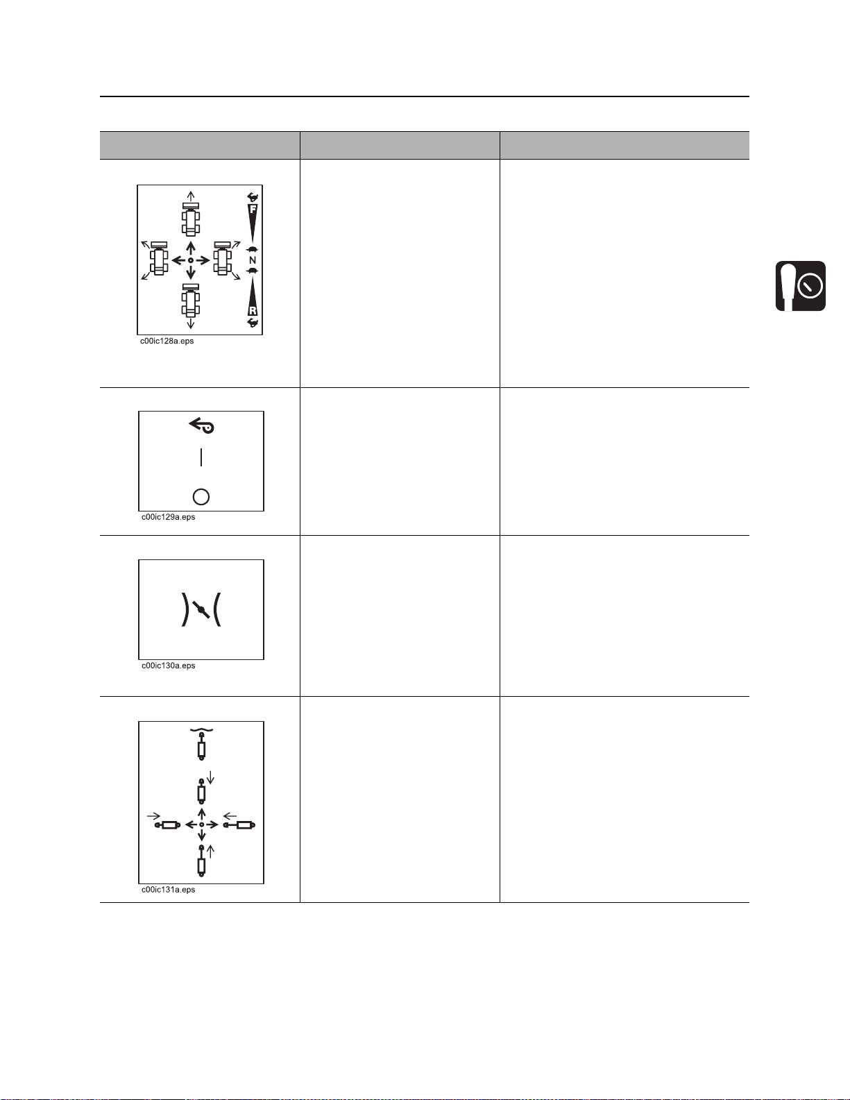
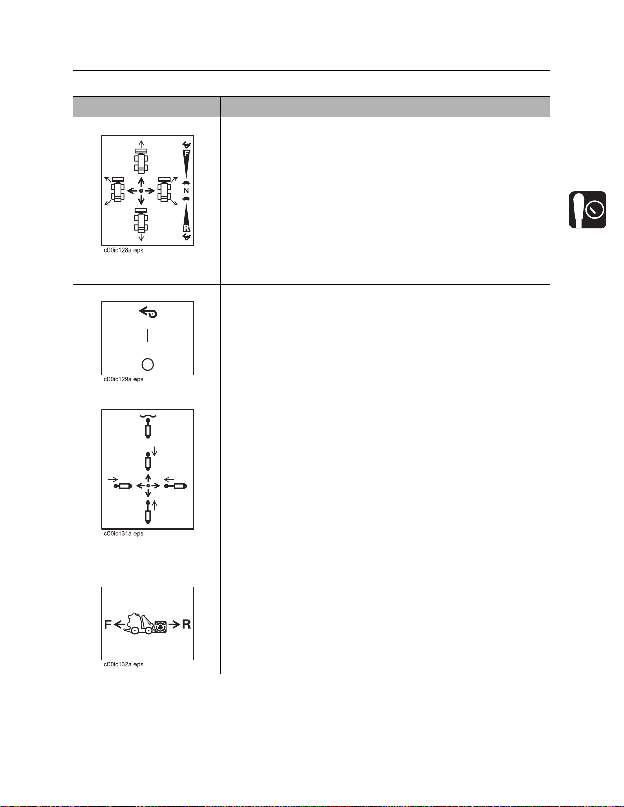
Controls
R150/R150E
1. Ground drive control
2. Traction assist switch
3. Throttle switch
4. Front end lift control
5. Front end drive control
CMW
6. Choke (R150)/manual start switch (R150E)
7. Rope start
8. Ignition switch
9. Parking brake
10. Cruise control pedal
Page 26
R150/R230/R300 Operator’s Manual Controls - 25
Controls
Item Description Notes
1. Ground drive control To move forward, push.
To move backward, pull.
To turn right, move to right.
To turn left, move to left.
To go faster in any direction,
move control farther from
neutral position.
To stop, release.
2. Traction assist switch To allow maximum power to
tires, press top.
To return to normal operation,
press bottom.
3. Throttle switch To set engine speed for
operation, press top.
To make a gradual turn, move control
halfway between desired directions
and return to center. Unit will remain
articulated until it is returned to center.
IMPORTANT: As long as control is
moved to right or left, unit is
articulating and turning is tightened.
Use when working on a slope to
lessen undesired movement.
To set speed to middle range
for transport, move to center
position
To decrease speed to idle,
press bottom.
4. Front end lift control To lower trencher, push.
To raise trencher, pull.
CMW
Page 27
Controls - 26 R150/R230/R300 Operator’s Manual
Controls
Item Description Notes
5. Front end drive control To engage front end drive in
reverse, lift lever release and
move to right.
To engage front end drive in
forward, lift lever release and
move to left.
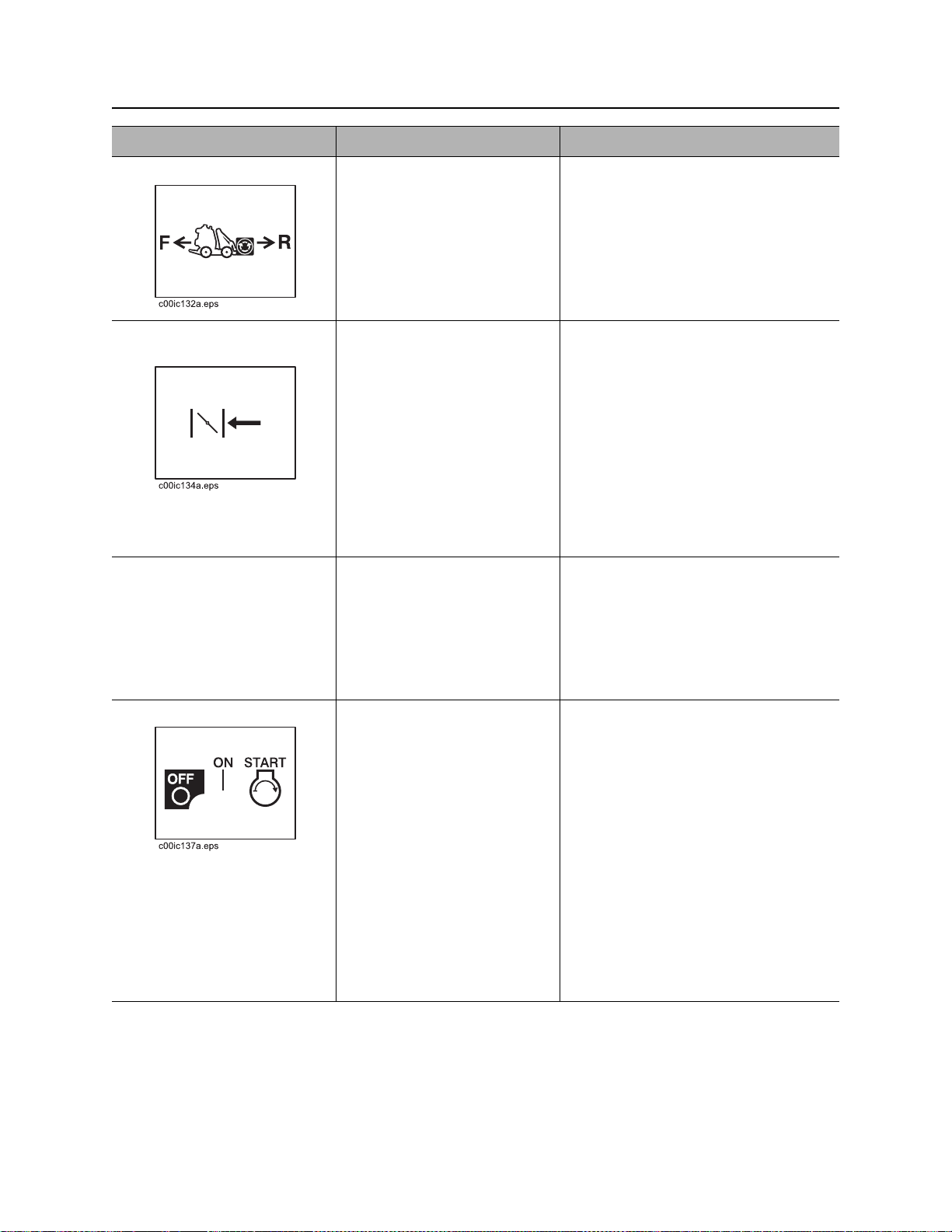
6. Choke/manual start
switch
7. Rope start To start engine, pull rope. Ignition switch must be on for this
8. Ignition switch R150
Choke (R150)
To help start cold engine,
close valve.
Manual start switch (R150E)
To manually start engine
when electric starter doesn’t
work, move switch to right,
turn on power switch and pull
rope start.
T o star t engine, insert key and
turn clockwise. Pull rope start.
This valve regulates air/fuel mixture.
IMPORTANT: R150E units have
automatic choke feature.
control to function.
If engine does not start after three
pulls, turn power switch off and check
for fuel blockage or electrical system
problems.
CMW
To stop engine, turn key
counterclockwise.
R150E
T o star t engine, insert key and
turn clockwise.
To stop engine, turn key
counterclockwise.
IMPORTANT:
• If engine does not start, turn key
to OFF and then restart.
• Do not allow starter motor to run
continuously for more than 20
seconds.
Page 28
R150/R230/R300 Operator’s Manual Controls - 27
Controls
Item Description Notes
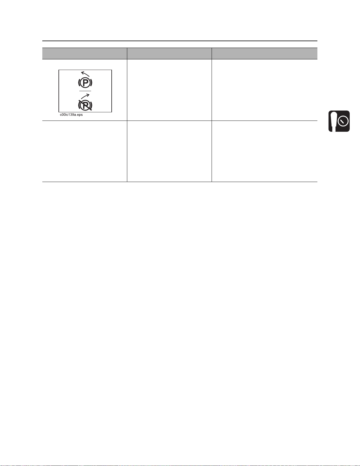
9. Parking brake lever To engage, move handle to
left.
To disengage, move handle
to right.
10. Cruise control pedal To maintain ground drive and
front end drive settings, press
pedal and release handles.
To adjust settings, grab drive
handles, step off pedal, adjust
drive settings, press pedal
and release handles.
IMPORTANT:
• Move unit slightly to ensure
parking brake pins are engaged.
• It might be necessary to move
unit slightly to disengage parking
brake.
NOTICE: Pedal must return to neutral
when released. Never tie down or use
anything other than foot to hold pedal
down.
CMW
Page 29
Controls - 28 R150/R230/R300 Operator’s Manual
Controls
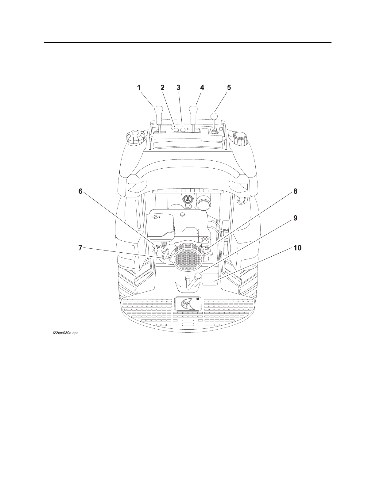
R230/R300
1. Ground drive control
2. Traction assist switch
3. Front end lift control
4. Front end drive control
5. Remote throttle control (optional)
CMW
6. Choke
7. Throttle
8. Ignition switch
9. Parking brake
10. Cruise control pedal
Page 30
R150/R230/R300 Operator’s Manual Controls - 29
Controls
Item Description Notes
1. Ground drive control To move forward, push.
To move backward, pull.
To turn right, move to right.
To turn left, move to left.
To go faster in any direction,
move control farther from
neutral position.
To stop, release.
2. Traction assist switch To allow maximum power to
tires, press top.
To return to normal operation,
press bottom.
3. Front end lift control To retract primary cylinder or
lower trencher, push.
To make a gradual turn, move control
halfway between desired directions
and return to center. Unit will remain
articulated until it is returned to center.
IMPORTANT: As long as control is
moved to right or left, unit is
articulating and turning is tightened.
Use when working on a slope to
lessen undesired track movement.
To float, push forward to
detent.
To extend primary cylinder or
raise trencher, pull.
To retract secondary cylinder,
move to left.
T o extend secondary cylinde r,
move to right.
4. Front end drive control To engage front end drive in
reverse, lift lever release and
move to right.
To engage front end drive in
forward, lift lever release and
move to left.
IMPORTANT: Front end will drop
when unit is put in float position.
CMW
Page 31

Controls - 30 R150/R230/R300 Operator’s Manual
Controls
Item Description Notes
5. Remote throttle control
(optional)
6. Choke To help start cold engine,
7. Throttle To increase engine speed,
To increase engine speed,
push.
To decrease engine speed,
pull.
move to left.
Move to right after engine has
warmed.
move to left.
To decrease engine speed,
move to right.
NOTICE: R300 unit s must be stopped
at full throttle to prevent backfiring.
This valve regulates air/fuel mixture.
This throttle is disengaged if remote
throttle is installed.
NOTICE: R300 unit s must be stopped
at full throttle to prevent backfiring.
8. Ignition switch T o star t engine, insert key and
turn clockwise.
To stop engine, turn key
counterclockwise.
9. Parking brake lever To engage, move handle to
left.
To disengage, move handle
to right.
NOTICE: R300 unit s must be stopped
at full throttle to prevent backfiring.
IMPORTANT:
• If engine does not start, turn key
to OFF and then restart.
• Do not allow starter motor to run
continuously for more than 20
seconds.
IMPORTANT:
• Move unit slightly to ensure
parking brake pins are engaged.
• It might be necessary to move
unit slightly to disengage parking
brake.
CMW
Page 32

R150/R230/R300 Operator’s Manual Controls - 31
Controls
Item Description Notes
10. Cruise control pedal To maintain ground drive and
front end drive settings, press
pedal and release handles.
To adjust settings, grab drive
handles, step off pedal, adjust
drive settings, press pedal
and release handles.
NOTICE: Pedal must return to neutral
when released. Never tie down or use
anything other than foot to hold pedal
down.
CMW
Page 33

Controls - 32 R150/R230/R300 Operator’s Manual
Controls
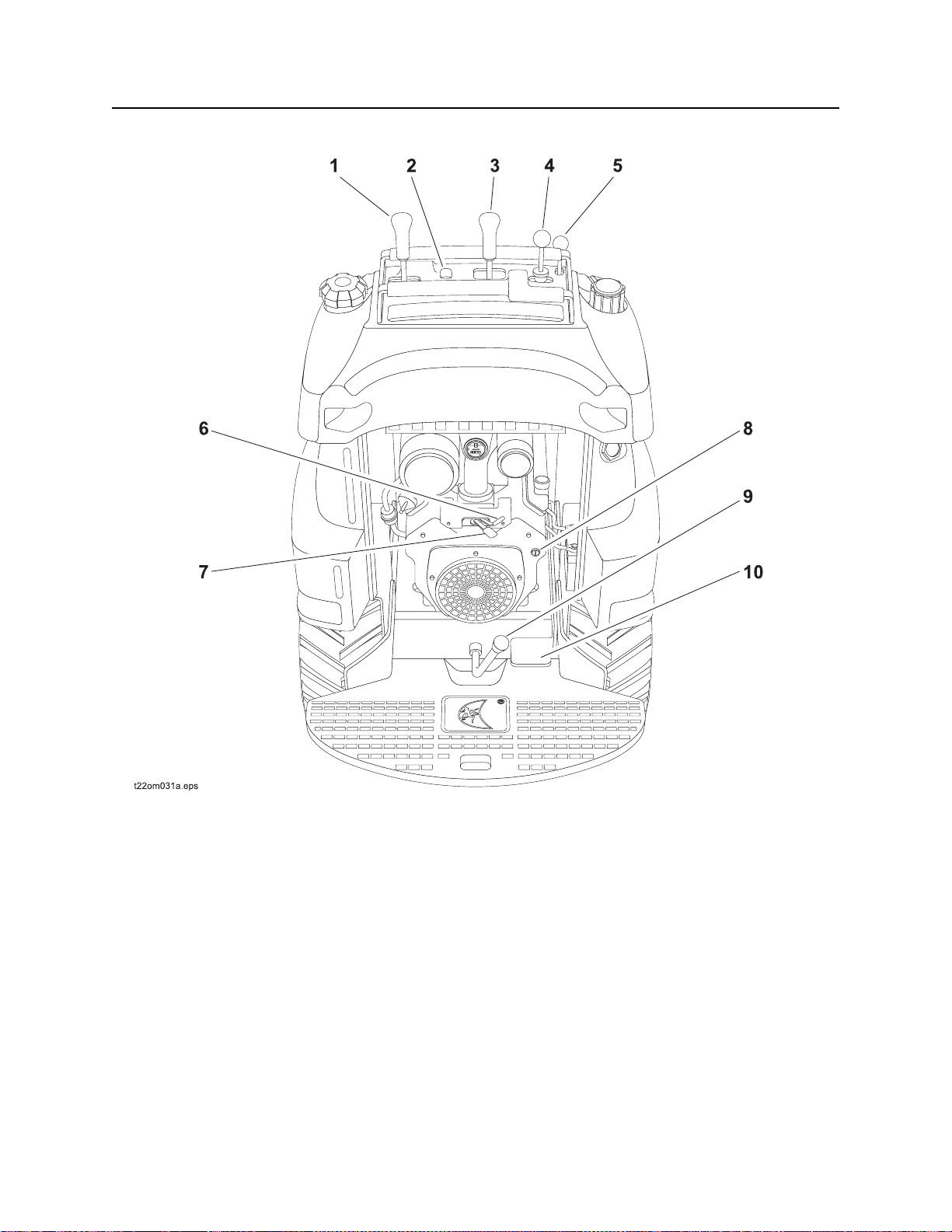
R150/R230/R300
1. Articulation lock To lock articulation joint, align
top and bottom holes and put
pin in hole (shown).
To unlock articulation joint,
return pin to storage hole.
Lock for transporting and lifting.
Unlock to maneuver unit.
CMW
Page 34

R150/R230/R300 Operator’s Manual Prepare - 33
Prep are
Chapter Contents
Gather Information . . . . . . . . . . . . . . . . . . . . . . . . . 34
Inspect Site . . . . . . . . . . . . . . . . . . . . . . . . . . . . . . . 35
• Identify Hazards . . . . . . . . . . . . . . . . . . . . . . . . . . . . . . . . . . . . . . . . . . .35
Classify Jobsite . . . . . . . . . . . . . . . . . . . . . . . . . . . 36
• Inspect Jobsite . . . . . . . . . . . . . . . . . . . . . . . . . . . . . . . . . . . . . . . . . . . .36
• Select a Classification . . . . . . . . . . . . . . . . . . . . . . . . . . . . . . . . . . . . . .36
• Apply Precautions . . . . . . . . . . . . . . . . . . . . . . . . . . . . . . . . . . . . . . . . .37
Check Supplies and Prepare Equipment . . . . . . . 38
• Supplies . . . . . . . . . . . . . . . . . . . . . . . . . . . . . . . . . . . . . . . . . . . . . . . . .38
• Fluid Levels . . . . . . . . . . . . . . . . . . . . . . . . . . . . . . . . . . . . . . . . . . . . . .38
• Condition and Function . . . . . . . . . . . . . . . . . . . . . . . . . . . . . . . . . . . . .38
• Accessories . . . . . . . . . . . . . . . . . . . . . . . . . . . . . . . . . . . . . . . . . . . . . .38
Attach Front End to InterChange Connection . . . 38
CMW
Page 35

Prepare - 34 R150/R230/R300 Operator’s Manual
Gather Information
Gather Information
A successful job begins before you start working. The fi rst step in planning is reviewing information already
available about the job and jobsite.
Review Job Plan
Review blueprints or other plans. Check for information about exi sting or planned structur es, elevations, or
proposed work that may be taking place at the same time.
Arrange for Traffic Control
If working near a road or other traffic area, contact local authorities about safety procedures and
regulations.
Plan for Emergency Services
Have the telephone numbers for local emergency and medical facilities on hand. Check that you will have
access to a telephone.
Notify One-Call Services
Contact your local One-Call (811 in USA) or the One-Call referral number (888-258-0808 in USA and
Canada) to have underground utilities located before digging. Also contact any utilities that do not
participate in the One-Call service.
CMW
Page 36

R150/R230/R300 Operator’s Manual Prepare - 35
Inspect Site
Inspect Site
Inspect jobsite before transporting equipment. Check for the following:
• changes in elevation such as hills or other open trenches
• obstacles such as buildings, railroad crossings, or streams
• signs of utilities (See “Inspect Jobsite” on page 36.)
•traffic
•access
• soil type and condition
Identify Hazards
Identify safety hazards and classify jobsite if front end or attachment will penetrate ground. See “Classify
Jobsite” on page 36.
Jobsite hazards could cause death or serious injury. Use
correct equipment and work methods. Use and maintain proper safety
equipment.
NOTICE:
• Wear personal protective equipment including hard hat, safety eye wear, and hearing protection.
• Do not wear jewelry or loose clothing.
• Notify One-Call and companies which do not subscribe to One-Call.
• Comply with all utility notification regulations before digging or drilling.
• Verify location of previously marked underground hazards.
• Mark jobsite clearly and keep spectators away.
Remember, jobsite is classified by hazards in place -- not by line being installed.
CMW
Page 37

Prepare - 36 R150/R230/R300 Operator’s Manual
Classify Jobsite
Classify Jobsite
Inspect Jobsite
• Inspect jobsite and perimeter for evidence of underground hazards, such as:
– “buried utility” notices
– utility facilities without overhead lines
– gas or water meters
– junction boxes
– drop boxes
– light poles
– manhole covers
– sunken ground
• Follow U.S. Department of Labor regulations on excavating and trenching (Part 1926, Subpar t P) and
other similar regulations.
• Contact your local One-Call (811 in USA) or the One-Call referral number (888-258-0808 in USA and
Canada) to have underground utilities located before digging. Also contact any utilities that do not
participate in the One-Call service.
• Have an experienced locating equipment operator sweep area within 20’ (6 m) to each side of work
path. Verify previously marked line and cable locations.
• Mark location of all buried utilities and obstructions.
• Classify jobsite.
Select a Classification
Jobsites are classified according to underground hazards present.
If working . . . then classify jobsite as . . .
within 10’ (3 m) of a buried electric line electric
within 10’ (3 m) of a natural gas line natural gas
in sand or granite which is capable of producing crystalline silica
(quartz) dust
within 10’ (3 m) of any other hazard other
NOTICE: If you have any doubt about jobsite classification, or if jobsite might contain unmarked
hazards, take steps outlined previously to identify hazards and classify jobs ite be fo re wor kin g.
crystalline silica (quartz) dust
CMW
Page 38

R150/R230/R300 Operator’s Manual Prepare - 37
Classify Jobsite
Apply Precautions
Once classified, precautions appropriate for jobsite must be taken.
Electric Jobsite Precautions
Use one or both of these methods.
• Expose line by careful hand digging or soft excavation.
• Have service shut down while work is in progress. Have electric company test lines before returning
them to service.
Natural Gas Jobsite Precautions
In addition to positioning equipment upwind from gas lines, use one or both of these methods.
• Expose lines by careful hand digging or soft excavation.
• Have gas shut off while work is in progress. Have gas company test lines before returning them to
service.
Crystalline Silica (Quartz) Dust Precautions
Follow OSHA or other guidelines for exposure to crystalline silica when trenching, sawing or drilling
through material that might produce dust containing crystalline silica (quartz).
Other Jobsite Precautions
You may need to use different methods to safely avoid other underground hazards. Talk with those
knowledgeable about hazards present at each site to determine which precautions should be taken or if
job should be attempted.
CMW
Page 39

Prepare - 38 R150/R230/R300 Operator’s Manual
Check Supplies and Prepare Equipment
Check Supplies and Prepare Equipment
Supplies
•fuel
•lubricants
Fluid Levels
•fuel
• hydraulic fluid
• battery charge
• engine oil
Condition and Function
• parking brake pins (see “Check Parking Brake Operatio n” on page 65)
• filters (air, oil, hydraulic)
• pumps and motors
• hoses and valves
• signs, guards, and shields
Accessories
Fire Extinguisher
Mount a fire extinguisher near the power unit but away from possible points of ignition. The fire
extinguisher should always be classified for both oil and electric fires. It should meet legal and regulatory
requirements.
Attach Front End to InterChange Connection
Precautions
IMPORTANT: Use only Ditch Witch-approved front ends and attachments. Other front ends and
attachments will change the stability and operating characteristics of the unit.
See front end operation sheet for instructions for connecting/disconnecting front ends.
CMW
Page 40

R150/R230/R300 Operator’s Manual Drive - 39
Drive
Chapter Contents
Start Unit . . . . . . . . . . . . . . . . . . . . . . . . . . . . . . . . . 40
Drive . . . . . . . . . . . . . . . . . . . . . . . . . . . . . . . . . . . . 41
Shut Down . . . . . . . . . . . . . . . . . . . . . . . . . . . . . . . 42
CMW
Page 41

Drive - 40 R150/R230/R300 Operator’s Manual
Start Unit
Start Unit
EMERGENCY SHUTDOWN: Release all controls (including cruise control pedal) and turn ignition
switch to OFF
R150
1. Ensure all controls are in neutral and parking brake is engaged.
2. Turn key to on position.
3. Move throttle switch to center position.
4. Choke engine, if necessary.
5. Pull rope or turn ignition switch to start position and release when engine starts.
R230/R300
1. Ensure all controls are in neutral and parking brake is engaged.
.
2. Move throttle to half open.
3. Choke engine, if necessary.
4. Turn ignition switch to start position and release when engine starts. See “Ignitio n switch” on page 30.
CMW
Page 42

R150/R230/R300 Operator’s Manual Drive - 41
Drive
Drive
Incorrect procedures could result in death, injury, or property damage.
Learn to use equipment correctly.
NOTICE: Operate unit only while standing on platform.
General Operation
Tipover possible. Machine can tip over and crush you.
• Always operate with load end uphill.
• Always carry load low. High load can cause tipping, loss of load or loss of visibility.
• Never jerk control levers. Use a steady even motion.
1. Disengage parking brake.
2. Pull front end lift control to raise front end off ground.
3. Move ground drive control to forward or reverse.
4. Adjust throttle as needed.
5. Move ground drive control to side to steer in that direction.
IMPORTANT: For continuous ground drive and front end drive opera tion, use cruise control ped al.
See “Cruise control pedal” on page 27.
Slope Operation Guidelines
• Engage traction control when working on a slope to lessen undesired movement.
• Keep heavy end of unit uphill on slopes.
• Avoid starting, stopping, or turning on slopes. If you must turn, keep the heavy end of the unit uphill.
• Avoid parking unit on a slope. If parking on a slope cannot be avoided, lower fro nt end, engage p arking
brake and turn ignition switch to OFF.
CMW
Page 43

Drive - 42 R150/R230/R300 Operator’s Manual
Shut Down
Shut Down
1. Lower front end to ground.
2. Move all controls to neutral position.
3. Engage parking brake.
4. Move throttle to center position (R150) or to full open (R230/R300).
5. Turn ignition switch to OFF.
6. Remove key.
CMW
Page 44

R150/R230/R300 Operator’s Manual Transport - 43
Transport
Chapter Contents
Lift . . . . . . . . . . . . . . . . . . . . . . . . . . . . . . . . . . . . . . 44
• Points . . . . . . . . . . . . . . . . . . . . . . . . . . . . . . . . . . . . . . . . . . . . . . . . . . .44
• Procedure . . . . . . . . . . . . . . . . . . . . . . . . . . . . . . . . . . . . . . . . . . . . . . . .45
Haul . . . . . . . . . . . . . . . . . . . . . . . . . . . . . . . . . . . . . 46
• Load . . . . . . . . . . . . . . . . . . . . . . . . . . . . . . . . . . . . . . . . . . . . . . . . . . . .46
• Tie Down . . . . . . . . . . . . . . . . . . . . . . . . . . . . . . . . . . . . . . . . . . . . . . . .47
• Unload . . . . . . . . . . . . . . . . . . . . . . . . . . . . . . . . . . . . . . . . . . . . . . . . . .48
Tow . . . . . . . . . . . . . . . . . . . . . . . . . . . . . . . . . . . . . 49
CMW
Page 45

Transport - 44 R150/R230/R300 Operator’s Manual
Lift
Lift
Crushing weight. If load falls or moves it could kill or crush you. Use
proper procedures and equipment or st ay away.
Points
Lifting points are identified by lifting decals. Lifting at other points is unsafe
and can damage machinery.
CMW
Page 46

R150/R230/R300 Operator’s Manual Transport - 45
Lift
Procedure
Use a hoist capable of supporting the equipment's size and weight. See “Specifications” on page 81 or
measure and weigh equipment before lifting.
Configured trencher Configured 4-wheel drive unit only
Lock articulation joint and use three lift points as
shown.
Lock articulation joint and use four lift points as
shown.
To lift configured 4-wheel drive unit with front end, see appropriate front end operation sheet.
CMW
Page 47

Transport - 46 R150/R230/R300 Operator’s Manual
Haul
Haul
IMPORTANT: For trailer information, see the trailer manufacturer’s manual.
Load
Crushing weight. If load falls or moves it could kill or crush you. Use
proper procedures and equipment or st ay away.
Tipover possible. Machine can tip over and crush you.
• Always operate with heavy end uphill.
• Lock articulation joint when transporting.
IMPORTANT: Do not remove front end from InterChange connection before loading or unloading power
unit.
1. Disengage parking brake.
2. Start engine and slow to low throttle.
3. Pull front end lift control to raise front end clear of trailer, but keep it low.
4. Move unit to rear of trailer and align with ramps.
5. Move ground drive control forward and slowly
move unit onto trailer until tiedown position is
reached.
NOTICE:
• If loading onto tilt-bed trailer, be
prepared for trailer bed to tilt.
• Move all controls to neutral position
when stopped.
6. Push front end lift control to lower front end to
trailer bed.
7. Engage parking brake and turn ignition switch
to OFF.
8. Lock articulation joint.
9. Close fuel tank shutoff valve (shown).
10. Tie down unit.
CMW
Page 48

R150/R230/R300 Operator’s Manual Transport - 47
Haul
Tie Down
Points
Tiedown points are identified by tiedown decals. Securing to truck or trailer
at other points is unsafe and can damage machinery.
Procedure
Configured Trencher
Loop tiedowns around unit at tiedown points.
Make sure tiedowns are tight before
transporting.
Other Front Ends
To tie down unit with any other front end, see appropriate front end operation sheet.
IMPORTANT:
• Do not remove front end from InterChange connection before loading or unloading unit.
• Use a crane or hoist if loading additional front ends onto trailer.
CMW
Page 49

Transport - 48 R150/R230/R300 Operator’s Manual
Haul
Unload
Crushing weight. If load falls or moves it could kill or crush you. Use
proper procedures and equipment or st ay away.
Tipover possible. Machine can tip over and crush you. Always operate
with heavy end uphill.
IMPORTANT: Do not remove front end from InterChange connection before loading or unloading power
unit.
1. Lower trailer or ramps and remove tiedowns .
2. Unlock articulation joint.
3. Open fuel tank shutoff valve.
4. Start engine and disengage parking brake.
5. Pull front end lift control to raise front end, but keep it low.
6. Slow engine to low throttle and slowly back unit down trailer or ramps.
NOTICE: If unloading from tilt-bed trailer, be prepared for trailer bed to tilt.
CMW
Page 50

R150/R230/R300 Operator’s Manual Transport - 49
Tow
Tow
Under normal conditions, unit should not be
towed. If unit breaks down and towing is
necessary:
• attach chains to tow point (shown) facing
towing vehicle
• tow for short distances at less than 1 mph
(1.6 km/h)
• do not tow for more than 100’ (30 m)
• use no more than 1,300 lb (5800 N) of
towing force
• disengage parking brake as shown
CMW
Page 51

Transport - 50 R150/R230/R300 Operator’s Manual
Tow
Prepare Unit for Towing
1. Ensure parking brake is engaged.
2. Block wheels.
3. Connect to tow point.
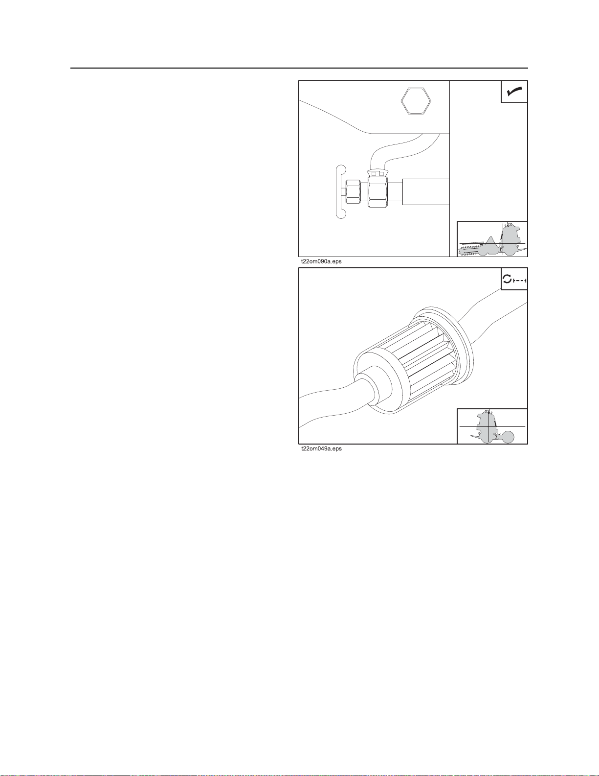
4. Turn tow valve (shown).
• R150 (top illustration): Turn
counterclockwise two turns.
• R230/R300 (bottom illustration): Turn
counterclockwise 1/4 turn.
5. Disengage parking brake. See “Parking brake
lever” on page 27.
6. Unblock wheels.
Return Unit to Normal Operation
1. Engage parking brake.
2. Block wheels.
3. Disconnect from tow point.
4. Turn tow valve.
• R150 (top illustration): Turn clockwise
two turns.
• R230/R300 (bottom illustration): Turn
clockwise 1/4 turn.
5. Unblock wheels.
6. Disengage parking brake. See “Parking brake
lever” on page 27.
CMW
Page 52

R150/R230/R300 Operator’s Manual Trench - 51
Trench
Chapter Contents
Trench . . . . . . . . . . . . . . . . . . . . . . . . . . . . . . . . . . . 53
Page 53

Trench - 52 R150/R230/R300 Operator’s Manual
Electrical shock. Contacting electrical lines will cause death or serious
injury. Know location of lines and stay away.
NOTICE: Cutting high voltage cable can cause electrocuti on. Expose lines by hand befo re
digging.
Incorrect procedures could result in death, injury, or property damage.
Learn to use equipment correctly.
NOTICE:
• Comply with all utility notification regulations before digging or drilling.
• Notify companies that do not subscribe to One-Call.
safety glasses.
Flying objects thrown by machine may strike people. Wear hard hat and
Page 54

R150/R230/R300 Operator’s Manual Trench - 53
Trench
Trench
Moving digging teeth will cause death or serious injury. Stay away.
NOTICE:
• Keep everyone at lease 6’ (2 m) from machine, digging boom, and its range of movement.
• Machine may move when chain starts to dig. Allow 3’ (1 m) between end of chain and obstacle.
• Operate unit only while standing on platform.
1. Move unit to starting point of trench.
IMPORTANT:
• When beginning trench near a wall or fence, allow enough distance between boom and
footings, drains, and cables.
• When cutting across asphalt roads , start trenc h in soil at edg e of roa d an d dig with bo o m at
full digging depth.
• When straight trenching across a slope, it can be helpful to stake a wooden beam parallel to
intended course and just far enough from trench to guide downslope wheels.
2. Engage parking brake and move throttle to half open.
3. Use front end lift control to lower trencher to 1" (25 mm) above ground surface.
4. Use front end drive control to start forward digg ing chain rotation. DIGGING CHAIN WILL MOVE.
5. Increase engine speed to full throttle.
6. Use front end lift control to slowly lower digging boom to digging depth.
Page 55

Trench - 54 R150/R230/R300 Operator’s Manual
Trench
7. Disengage parking brake and pull ground drive control to begin trenching. UNIT WILL MOVE.
IMPORTANT:
• Trenching movement is toward you.
• For easier turning, lower boom to full depth.
• If an object becomes lodged in chain, move digging chain control to neutral and raise boom
slightly. Reverse chain direction. If object must be removed manually, stop engine.
8. For continuous ground drive and front end drive operation, use cruise control pedal. See “Cruise
control pedal” on page 27.
9. When trench is complete, move ground drive control to neutral.
10. Move throttle to half open.
11. Use front end lift control to raise boom to top of trench.
12. Use front end drive control to stop digging chain rotation.
13. Use front end lift control to raise trencher.
14. Use ground drive control to drive unit away from trench.
15. Lower trencher to ground surface.
16. Stop engine.
Page 56

R150/R230/R300 Operator’s Manual Systems and Equipment - 55
Systems and Equipment
Chapter Contents
Chain, Teeth, and Sprockets . . . . . . . . . . . . . . . . . 56
• Chain and Tooth Maintenance . . . . . . . . . . . . . . . . . . . . . . . . . . . . . . . .56
• Chain Types . . . . . . . . . . . . . . . . . . . . . . . . . . . . . . . . . . . . . . . . . . . . . .56
• Chain Selection . . . . . . . . . . . . . . . . . . . . . . . . . . . . . . . . . . . . . . . . . . .57
Optional Equipment . . . . . . . . . . . . . . . . . . . . . . . . 58
Page 57

Systems and Equipment - 56 R150/R230/R300 Operator’s Manual
Chain, Teeth, and Sprockets
Chain, Teeth, and Sprockets
Chain and Tooth Maintenance
• Always replace sprockets at the same time you replace the digging chain. Sprockets and chain are
designed to work together. Replacing one without the other will cause premature wear of the new part.
• Keep digging teeth sharp. Using dull, worn teeth will decrease production and increase shock load to
other trencher components. It can also cause chain stretch, which leads to premature chain wear and
failure.
• Maintain the proper amount of tension on the digging chain. Overtightening will cause chain stretch
and loss of machine performance. For correct tightening procedure, see pag e 67.
• Use the tooth pattern most appropriate for your digging conditions. If you move to a different soil type,
contact your Ditch Witch dealer for information about the most effective chain type and tooth pattern.
Chain Types
Chain type Features
4-pitch standard chain
2-pitch more teeth for smoother cuttin g
alternating side bar prevents spoil compaction on chain
bolt-on adapters allow easy configuration changes
Shark Chain II versatile, virtually maintenance- fr ee
combination provides pick and shovel effect
Page 58

R150/R230/R300 Operator’s Manual Systems and Equipment - 57
Chain, Teeth, and Sprockets
Chain Selection
These charts are meant as a guideline only. No one chain type works well in all conditions. See your Ditch
Witch dealer for soil conditions and chain recommendations for your area. Ask for the latest Chain, Teeth,
and Sprockets Parts Catalog.
• 1 = best
• 2 = better
• 3 = good
• 4 = not recommended
Chain Sandy
Soil
4-pitch cup tooth 3 1 2 3 4 1
2-pitch cup tooth 2 3 1 1 3 4
bolt-on adaptor, 2-pitch 4 4 3 2 1 4
bolt-on adaptor/cup tooth
combo
Shark Chain II 432114
alternating side bar 4 4 4 4 4 1
Soil Description
sandy soil sugar sand, blow sand, or other soils where sand is the predominant component
soft soil sandy loam
medium soil loams, loamy clays
hard soil packed clays, gumbo, all compacted soils
432124
Soft Soil Medium
Soil
Hard Soil Rocky
Soil
Sticky
Soil
rocky soil chunk rock, glacial till, cobble, rip rap, gravel
sticky soil gumbo, sticky clays
Page 59

Systems and Equipment - 58 R150/R230/R300 Operator’s Manual
Optional Equipment
Optional Equipment
See your Ditch Witch dealer for information about available optional equipment.
Page 60

R150/R230/R300 Operator’s Manual Complete the Job - 59
Complete the Job
Chapter Contents
Restore Jobsite. . . . . . . . . . . . . . . . . . . . . . . . . . . . 60
• Backfilling . . . . . . . . . . . . . . . . . . . . . . . . . . . . . . . . . . . . . . . . . . . . . . . .60
Rinse Equipment . . . . . . . . . . . . . . . . . . . . . . . . . . 60
Stow Tools . . . . . . . . . . . . . . . . . . . . . . . . . . . . . . . 60
CMW
Page 61

Complete the Job - 60 R150/R230/R300 Operator’s Manual
Restore Jobsite
Restore Jobsite
After product is installed, return spoils to the trench with optional backfill blade.
Backfilling
1. Turn off engine.
2. Install backfill blade and secure with pull pins,
as shown.
3. Start unit.
4. Position unit at end of trench, several feet
from spoils. Aim unit at outer edge of spoils.
5. Adjust backfill blade to fit land contour.
6. Move outer edge of spoils toward trench.
Take two or more passes at spoils rather than
moving all spoils at once.
7. Repeat on other side of trench, if necessary.
8.
Rinse Equipment
Spray water onto equipment to remove dirt and mud.
NOTICE: Do not spray water onto operator’s console. Electrical components could be damaged. Wipe
down instead.
Stow Tools
Make sure all tools and accessories are loaded and secured on trailer.
CMW
Page 62

R150/R230/R300 Operator’s Manual Service - 61
Service
Chapter Contents
Service Precautions . . . . . . . . . . . . . . . . . . . . . . . . 62
Recommended Lubricants/Service Key . . . . . . . . 62
Oil Temperature Chart . . . . . . . . . . . . . . . . . . . . . . 63
Each Use . . . . . . . . . . . . . . . . . . . . . . . . . . . . . . . . . 64
10 Hour . . . . . . . . . . . . . . . . . . . . . . . . . . . . . . . . . . 66
20 Hour . . . . . . . . . . . . . . . . . . . . . . . . . . . . . . . . . . 69
50 Hour . . . . . . . . . . . . . . . . . . . . . . . . . . . . . . . . . . 71
100 Hour . . . . . . . . . . . . . . . . . . . . . . . . . . . . . . . . . 73
250 Hour . . . . . . . . . . . . . . . . . . . . . . . . . . . . . . . . . 75
500 Hour . . . . . . . . . . . . . . . . . . . . . . . . . . . . . . . . . 77
As Needed . . . . . . . . . . . . . . . . . . . . . . . . . . . . . . . 78
CMW
Page 63

Service - 62 R150/R230/R300 Operator’s Manual
Service Precautions
Service Precautions
Incorrect procedures could result in death, injury, or property damage.
Learn to use equipment correctly.
NOTICES:
• Unless otherwise instructed, all service should be performed with engine off.
• Refer to engine manufacturer’s manual for engine maintenance instructions.
• Before servicing equipment, lower unstowed front ends to ground .
Recommended Lubricants/Service Key
Item Description
GEO Gasoline engine oil meeting current API service classifications and SAE viscosity
recommended by engine manufacturer (SAE 10W30)
MPG Multipurpose grease meeting ASTM D217 and NLGI 3
THF Tractor hydraulic fluid, similar to Phillips 66 HG, Mobilfluid 423, Chevron Tractor
Hydraulic Fluid, Texaco TDH Oil, or equivalent
Check level of fluid or lubricant
Check condition
Filter
Change, replace, adjust, service or test
Proper lubrication and maintenance protects Ditch Witch equipment from damage and failure. Service
intervals listed are for minimum requirements. In ex treme conditions, service machine more frequently.
Use only recommended lubricants. Fill to capacities listed in “Specifications” on page 81.
NOTICE:
• Use only genuine Ditch Witch parts, filters, and approved lubricants to maintain warranty.
• Use the “Service Record” on page 103 to record all required service to your machine.
CMW
Page 64

R150/R230/R300 Operator’s Manual Service - 63
Engine Oil Temperature Chart
Engine Oil Temperature Chart
R150
Temperature range anticipated before next oil change
R230/R300
Temperature range anticipated before next oil change
For more information on engine lubrication and maintenance, see your engine manual.
CMW
Page 65

Service - 64 R150/R230/R300 Operator’s Manual
Each Use
Each Use
Location Task Notes
Power Unit Check engine oil level GEO
Check hydraulic fluid level THF
Check parking brake operation
Check tires Bar lug tire: 12 psi (82.7 kPa)
Turf tire: 22 psi (151 kPa)
Lug nut torque: 65-70 ft•lb
(88-95 N•m)
Power Unit
Check Engine Oil Level - R150
Check engine oil at dipstick (1) before each use.
If low, add GEO until oil level is at highest line on
dipstick.
IMPORTANT: For more info rm a tio n on eng in e
oil, see “Recommended Lubricants/Service
Key” on page 62 or see engine manual.
Check Engine Oil Level - R230/R300
Check engine oil at dipstick (1) before each use.
If low, add GEO until oil level is at highest line on
dipstick.
IMPORTANT: For more info rm a tio n on eng in e
oil, see “Recommended Lubricants/Service
Key” on page 62 or see engine manual.
CMW
Page 66

R150/R230/R300 Operator’s Manual Service - 65
Each Use
Check Hydraulic Fluid Level
With digging boom fully raised, check hydraulic
fluid level at sight glass (2) before each use. If
low, add THF until level is at halfway point on
sight glass. Clean dust from cap (1) by blowing
with low pressure air.
Check Parking Brake Operation
Verify that parking brake pins engage as shown
before each use.
Check Tires
Check power unit tire pressure (2, if necessary)
before each use. Maintain pressure as indicated
below.
• Bar lug tire: 12 psi (82.7 kPa).
• Turf tire: 22 psi (151 kPa).
Check lug nut (1) tightness before each use.
Tighten to 65-70 ft•lb (88-95 N•m).
CMW
Page 67

Service - 66 R150/R230/R300 Operator’s Manual
10 Hour
10 Hour
Location Task Notes
Power Unit Check hydraulic hoses
Inspect insulation R150 only
Trencher Lube trencher pivot MPG
Lube trencher headshaft bearing MPG
Check digging chain tension MPG
Power Unit
Check Hydraulic Hoses
Check hydraulic hoses for leaks every 10 hours.
Fluid or air pressure could pierce skin and cause injury or
death. Stay away.
NOTICE: Escaping pressurized fluid can cause injury or pierce skin and poison.
• Before disconnecting a hydraulic line, turn engine off and ope rate all controls to relieve pressure.
Lower, blo ck, or support any raised component with a hoist. Cover connectio n with heavy cloth and
loosen connector nut slightly to relieve residual pressure. Catch all fluid in a container.
• Before using system, check that all connections are tight and all lines are undamaged.
• Fluid leaks can be hard to detect. Use a piece of cardboard or wood, rather than hands, to search
for leaks.
• Wear protective clothing, including gloves and eye protection.
If you are injured, seek immediate medical attention from a doctor familiar with this type of injury.
CMW
Page 68

R150/R230/R300 Operator’s Manual Service - 67
10 Hour
Inspect Insulation (R150 units only)
Inspect heat insulation on R150 fuel tank (1) and
fuel line (2) for damage every 10 hours. Replace
if damaged.
1
2
Trencher
Lube Trencher Pivot
Lube two pivot zerks with MPG every 10 hours.
Lube Headshaft Bearings
Lube headshaft bearing with MPG every 10
hours.
t22om001t.eps
t22om001t.eps
CMW
Page 69

Service - 68 R150/R230/R300 Operator’s Manual
10 Hour
Check Digging Chain Tension
NOTICE: Do not overtighten chain.
Overtightening will cause chain stretch, loss of
machine performance, and possible premature
chain failure.
Check digging chain tension every 10 hours and
adjust as needed. With boom horizont al, measure
distance from bottom of boom to chain. When
properly tensioned, distance (A) should be 1.5”
(38 mm).
Adjustment Screw:
1. Loosen four clamp bolts (2) so that boom
slides freely .
2. Loosen jam nut on adjustment screw (1).
3. To tighten digging chain, turn adjustment
screw clockwise. To loosen digging chain,
turn counterclockwise.
4. When proper tension is reached, tighten jam
nut.
5. Tighten clamp bolts to 75 ft•lb (102 N•m).
Grease Cylinder:
To tighten digging chain, pump MPG into cylinder
at check valve zerk.
T o loosen digging chain , stand on opposite side of
boom and unscrew check valve zerk to release
grease.
Fluid pressure
could pierce skin and cause
injury or death. Stay away.
NOTICE: Service digging boom grease
cylinder only while standing on opposite side of
boom. Wear gloves and safety glasses and
cover fitting with cloth when relieving pressure
in cylinder.
CMW
Page 70

R150/R230/R300 Operator’s Manual Service - 69
20 Hour
20 Hour
Location Task Notes
Power Unit Change engine oil - R150 Initial service, GEO
Change engine oil and filter - R230/R300 Initial service, GEO
Trencher Lube trail wheel MPG
Lube headshaft bearing MPG, headshaft auger
trencher only
Power Unit
Change Engine Oil (Initial) - R150
Change engine oil after the first 20 hours of
operation.
1. Move drain hose (1) to front of unit and drain
while oil is still warm.
2. Replace plug.
3. Add 1.6 qt (1.1 L) of GEO at fill neck (2).
IMPORTANT: If operating in extremely dusty
conditions, change oil more frequently. Use oil
specified in temperature chart found in
“Recommended Lubricants/Service Key” on
page 62.
CMW
Page 71

Service - 70 R150/R230/R300 Operator’s Manual
20 Hour
Change Engine Oil and Filter (Initial) R230/R300
Change engine oil and filter after the first 20
hours of operation.
1. Move drain hose (1) to front of unit and drain
while oil is still warm.
2. Replace plug.
3. Install new filter (3).
4. Add 2 qt (1.9 L) of GEO at fill neck (2).
IMPORTANT: If operating in extremely dusty
conditions, change oil more frequently. Use oil
specified in temperature chart found in
“Recommended Lubricants/Service Key” on
page 62.
Trencher
Lube Trail Wheel
Lube trail wheel with MPG every 20 hours.
CMW
Page 72

R150/R230/R300 Operator’s Manual Service - 71
50 Hour
Lube Headshaft Bearing (Headshaft
Auger Trencher Only)
Lube headshaft bearing with MPG every 20
hours.
50 Hour
Location Task Notes
Power Unit Check battery if equipped
Trencher Lube digging boom adjustment screw and stub, if
equipped
Lube digging boom stub, if equipped MPG
MPG
Power Unit
Check Battery
Check battery every 50 hours. Keep battery case
and terminals clean. Remove all corrosion from
terminals with a wire brush. Wash terminals with
a weak solution of baking soda and water.
CMW
Page 73

Service - 72 R150/R230/R300 Operator’s Manual
50 Hour
Trencher
Lube Digging Boom Adjustment
Screw and Stub
Lube adjustment screw and stub with MPG every
50 hours.
Lube Digging Boom Stub (Greaseable
Boom)
Lube boom stub with MPG every 50 hours.
CMW
Page 74

R150/R230/R300 Operator’s Manual Service - 73
100 Hour
100 Hour
Location Task Notes
Power Unit Change engine oil - R150 GEO
Change engine oil and filter - R230/R300 GEO
Change air filter
Power Unit
Change Engine Oil - R150
Change engine oil every 100.
1. Move drain hose (1) to front of unit and drain
while oil is still warm.
2. Replace plug.
3. Add 1.6 qt (1.1 L) of GEO at fill neck (2).
IMPORTANT: If operating in extremely dusty
conditions, change oil more frequently. Use oil
specified in temperature chart found in
“Recommended Lubricants/Service Key” on
page 62.
Change Engine Oil and Filter - R230/
R300
Change engine oil and filter every 100 hours.
1. Move drain hose (1) to front of unit and drain
while oil is still warm.
2. Replace plug.
3. Install new filter (3).
4. Add 2 qt (1.9 L) of GEO at fill neck (2).
IMPORTANT: If operating in extremely dusty
conditions, change oil more frequently. Use oil
specified in temperature chart found in
“Recommended Lubricants/Service Key” on
page 62.
CMW
Page 75

Service - 74 R150/R230/R300 Operator’s Manual
100 Hour
Change Air Filter - R150
Change air filter elements every 100 hours.
IMPORTANT: If operating in extremely dusty
conditions, change filter more frequently.
To change:
1. Remove wing nut (6) and air cleaner cover
(5).
2. Remove wing nut (4) and remove elements
(2, 3).
3. Reverse procedure to install new elements.
Ensure gasket (1) is seated properly.
Change Air Filter - R230/R300
Change air filter elements every 100 hours.
IMPORTANT: If operating in extremely dusty
conditions, change filter more frequently.
To change:
1. Unlatch and remove air cleaner cover (1).
2. Remove elements (2, 3) and replace.
3. Reverse procedure to install.
CMW
Page 76

R150/R230/R300 Operator’s Manual Service - 75
250 Hour
250 Hour
Location Task Notes
Power Unit Change hydraulic fluid and filter THF
Change fuel filter
Power Unit
Change Hydraulic Fluid and Filter
Change hydraulic fluid and filter every 250 hours.
1. Drain hydraulic fluid at drain (3).
2. Replace plug.
3. Change filter (shown).
4. Add THF at fill neck (1, above) until level is at
halfway point on sight glass (2, above).
CMW
Page 77
Service - 76 R150/R230/R300 Operator’s Manual
250 Hour
Change Fuel Filter
Close fuel tank shutoff (top illustration) and
change fuel filter (bottom illustration) every 200
hours. Open fuel tank shutoff before operating
unit.
CMW
Page 78

R150/R230/R300 Operator’s Manual Service - 77
500 Hour
500 Hour
Adjust Ground Drive Pump Neutral
(R230/R300 only)
Adjust neutral on ground drive pump every 500
hours or if spring is rusted or worn. Check
adjustment with throttle at low speed and
hydraulic fluid at operating temperature. Ensure
all neutral components are working properly
before adjusting.
To adjust
1. Use a hoist or appropriate jack stands to
reaise unit until all tires are off the ground.
2. Loosen bolts (1).
3. Start unit and brin g hydraulic fluid to
operating temperature.
4. Adjust throttle to full speed.
5. Disengage parking brake. Tires may turn.
6. Slowly rotate cam (2) until tires stop.
IMPORTANT: Tires may not come to a complete stop with unit raised. Adjust to achieve the least
tire movement possible.
7. Tighten bolts.
8. Engage parking brake.
9. Shut down unit.
10. Lower unit to ground.
CMW
Page 79

Service - 78 R150/R230/R300 Operator’s Manual
As Needed
As Needed
Location Task Notes
Power Unit Change fuses 15A, 30A
Clean cooler and screen
Adjust ground drive pump speed R230/R300 only
Adjust ground drive pump neutral
Set cruise control brake
Adjust cruise control brake
Power Unit
Change Fuses
Change fuses as needed.
• blue with red stripe wire is 15A
• orange with blue stripe wire is 30A
Clean Cooler and Screen
Clean hydraulic fluid cooler and screen as
needed.
IMPORTANT: All units have a cooler but only
the R230 and R300 have a screen.
1. Remove bolts (1) and rear cushion (2).
2. Pop out screen (3) and clean.
3. Clean cooler fins (4) with compressed air or
spray wash if required. Be careful not to
damage fins with high-pressure air or water.
4. Install screen and rear cushion and secure
with bolts.
CMW
Page 80
R150/R230/R300 Operator’s Manual Service - 79
As Needed
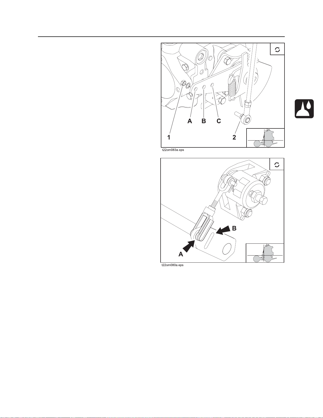
Adjust Ground Drive Pump Speed
(R230/R300 only)
Adjust ground drive pump speed as desired.
To adjust
1. Remove nut (1) and lock washer.
2. Move linkage (2) to hole that corresponds
with desired speed range.
• A is low
•B is medium
•C is high
3. Tighten nut.
Set Cruise Control Brake
Engage or disengage cruise control brake as
desired.
To engage, set arm as shown (A).
To disengage, move arm to slot (B).
CMW
Page 81

Service - 80 R150/R230/R300 Operator’s Manual
As Needed
Adjust Cruise Control Brake
Adjust cruise control brake as desired. Loose
brake allows more override. Tight brake allows
less override.
To adjust
1. Open arm (4) and remove pin.
2. Rotate linkage (1) counterclockwise to tighten
or clockwise to loosen.
3. If brake is still loose, loosen jam nut (2) and
turn screw (3) clockwise to tighten and
counterclockwise to loosen brake.
4. Rotate linkage as needed to adjust.
5. Reinstall arm.
CMW
Page 82

R150/R230/R300 Operator’s Manual Specifications - 81
Specifications
Chapter Contents
R150 . . . . . . . . . . . . . . . . . . . . . . . . . . . . . . . . . . . . 82
R230 with InterChange Connection . . . . . . . . . . . 85
R300 with InterChange Connection . . . . . . . . . . . 89
Power Unit with Headshaft Auger Trencher . . . . 93
Power Unit with Independent Auger Trencher . . 96
CMW
Page 83

Specifications - 82 R150/R230/R300 Operator’s Manual
R150
R150
Dimensions U.S. Metric
L Length 43 in 1.09 m
L6 Tractor back to rear axle 26.8 in 681 mm
L7 Rear axle to front end mounting 19.2 in 488 mm
H Height 53.5 in 1.36 m
H4 Ground clearance 5.3 in 135 mm
H10 Platform height 10.7 in 272 mm
W Width 36 in 914 mm
A Angle of departure 25° 25°
Mass
R150 968 lb 439 kg
R150E 1010 lb 458 kg
Vehicle clearance circle (SAE) wall to wall
Right turn 11.3 ft 3.44 m
Left turn 10.5 ft 3.2 m
Dimensions are based on unit equipped with urethane 18 X 9.5-8 tires unless otherwise specified.
CMW
Page 84

R150/R230/R300 Operator’s Manual Specifications - 83
R150
Operation U.S. Metric
Ground drive speed, forward 3.3 mph 5.3 km/h
Ground drive speed, reverse 3.3 mph 5.3 km/h
Ground pressure 16 psi 1.2 bar
Power U.S. Metric
Engine: Honda iGX440, gasoline
Cooling medium air
Number of cylinders 1
Displacement
Bore 3.46 in 88 mm
Stroke 2.84 in 72.1 mm
Manufacturer’s power rating 15 hp 9.5 kW
Rated speed 3600 rpm 3600 rpm
Power Train
Parking brake: mechanical, hand operated
Service brake: ground drive speed/direction control brakes machine hydraulically when moved to
neutral position
Tires U.S. Metric
18 X 9.5-8, 2 ply, bar lug
Pressure 12 psi 82.7 kpa
Tire assembly mass 22 lb 9.98 kg
Urethane filled 18 X 9.5-8, 2 ply, bar lug
26.7 in
3
438 cc
Pressure n/a n/a
Tire assembly mass 36 lb 16.33 kg
18 X 8.5-8, 2 ply, turf
Pressure 22 psi 151 kpa
Tire assembly mass 20 lb 9.07 kg
CMW
Page 85

Specifications - 84 R150/R230/R300 Operator’s Manual
R150
Hydraulic System U.S. Metric
Auxiliary: gear pump
Flow rate 7.4 gpm 28 L/min
Pressure 3000 psi 207 bar
Ground drive: hydrostat
Flow rate 11.4 gpm 43.2 L/min
Pressure 1800 psi 124 bar
Fluid Capacities U.S. Metric
Fuel tank 10.9 gal 41.3 L
Engine oil 1.6 qt 1.1 L
Hydraulic reservoir 7.7 gal 29.1 L
Total hydraulic system volume 8.5 gal 32.2 L
Battery (R150E only)
SAE reserve capacity 32 min, SAE cold crank @ 0°F (-18°C) 200 amp
Noise Levels
Operator 89 dBA sound pressure per ISO 6394
Exterior 101 dBA sound power per ISO 6393
Vibration Level
Vibration at the operator's hand duri ng normal operation can be up to 4.1 m/sec² per ISO 5349
Vibration at the operator’s foot during normal operation can be up to 8.5 m/sec² per ISO 2631
CMW
Page 86

R150/R230/R300 Operator’s Manual Specifications - 85
R230 with InterChange Connection
R230 with InterChange Connection
Dimensions U.S. Metric
L Driving length 70 in 1.78 m
L5 Wheelbase 34.2 in 869 mm
L6 Tractor back to rear axle 26.8 in 681 mm
L7 Rear axle to front end mounting 19.2 in 488 mm
L8 Front end mounting to front axle 15 in 381 mm
H Height 53.5 in 1.36 m
H4 Ground clearance 5.3 in 135 mm
H10 Platform height 10.7 in 272 mm
W Width 36 in 914 mm
A Angle of departure 25° 25°
Mass 1290 lb 585 kg
Vehicle clearance circle (SAE) wall to wall
Right turn 11.3 ft 3.44 m
Left turn 10.5 ft 3.2 m
Dimensions are based on unit equipped with urethane 18 X 9.5-8 tires unless otherwise specified.
CMW
Page 87

Specifications - 86 R150/R230/R300 Operator’s Manual
R230 with InterChange Connection
Operation (based on 18” tires) U.S. Metric
Ground drive speed, forward
Low 3.5 mph 5.6 km/h
High 5.0 mph 8.0 km/h
Ground drive speed, reverse
Low 3.5 mph 5.6 km/h
High 5.0 mph 8.0 km/h
Ground pressure 10 psi 0.7 bar
Power U.S. Metric
Engine: Kohler CH23S, gasoline
Cooling medium air
Number of cylinders 2
Displacement
Bore 3.15 in 80 mm
Stroke 2.64 in 67 mm
Manufacturer’s power rating 23 hp 17.2 kW
Rated speed 3600 rpm 3600 rpm
Power Train
Parking brake: mechanical, hand operated
Service brake: ground drive speed/direction control brakes machine hydraulically when moved to
neutral position
41.1 in
3
674 cc
CMW
Page 88

R150/R230/R300 Operator’s Manual Specifications - 87
R230 with InterChange Connection
Tires U.S. Metric
18 X 9.5-8, 2 ply, bar lug
Pressure 12 psi 82.7 kpa
Tire assembly mass 22 lb 9.98 kg
Urethane filled 18 X 9.5-8, 2 ply, bar lug
Pressure n/a n/a
Tire assembly mass 36 lb 16.33 kg
Urethane filled 20 X 10-8, 4 ply, bar lug
Pressure n/a n/a
Tire assembly mass 49 lb 22.23 kg
18 X 8.5-8, 2 ply, 2 turf
Pressure 22 psi 151 kpa
Tire assembly mass 20 lb 9.07 kg
Hydraulic System U.S. Metric
Auxiliary: gear pump
Flow rate 12 gpm 46 L/min
Pressure 3000 psi 207 bar
Ground drive: hydrostat
Flow rate 19.3 gpm 73 L/min
Pressure 3500 psi 241 bar
CMW
Page 89

Specifications - 88 R150/R230/R300 Operator’s Manual
R230 with InterChange Connection
Fluid Capacities U.S. Metric
Fuel tank 10.9 gal 41.3 L
Engine oil, with filter 2 qt 1.9 L
Hydraulic reservoir 7.7 gal 29.1 L
Total hydraulic system volume 8.5 gal 32.2 L
Battery
SAE reserve capacity 32 min, SAE cold crank @ 0°F (-18°C) 200 amp
Noise Levels
Operator 90 dBA sound pressure per ISO 6394
Exterior 102 dBA sound power per ISO 6393
Vibration Level
Vibration at the operator's hand duri ng normal operation can be up to 9.9 m/sec² per ISO 5349
Vibration at the operator’s foot during normal operation can be up to 8.5 m/sec² per ISO 2631
CMW
Page 90

R150/R230/R300 Operator’s Manual Specifications - 89
R300 with InterChange Connection
R300 with InterChange Connection
Dimensions U.S. Metric
L Driving length 70 in 1.78 m
L5 Wheelbase 34.2 in 869 mm
L6 Tractor back to rear axle 26.8 in 681 mm
L7 Rear axle to front end mounting 19.2 in 488 mm
L8 Front end mounting to front axle 15 in 381 mm
H Height 53.5 in 1.36 m
H4 Ground clearance 5.3 in 135 mm
H10 Platform height 10.7 in 272 mm
W Width 36 in 914 mm
A Angle of departure 25° 25°
Mass 1290 lb 585 kg
Vehicle clearance circle (SAE) wall to wall
Right turn 11.3 ft 3.44 m
Left turn 10.5 ft 3.2 m
Dimensions are based on unit equipped with urethane 18 X 9.5-8 tires unless otherwise specified.
CMW
Page 91

Specifications - 90 R150/R230/R300 Operator’s Manual
R300 with InterChange Connection
Operation (based on 18” tires) U.S. Metric
Ground drive speed, forward
Low 3.5 mph 5.6 km/h
High 5.0 mph 8.0 km/h
Ground drive speed, reverse
Low 3.5 mph 5.6 km/h
High 5.0 mph 8.0 km/h
Ground pressure 10 psi 0.7 bar
Power U.S. Metric
Engine: Kohler CH750S, gasoline
Cooling medium air
Number of cylinders 2
Displacement
Bore 3.3 in 83 mm
Stroke 2.7 in 69 mm
Manufacturer’s power rating 30 hp 22.4 kW
Rated speed 3600 rpm 3600 rpm
Power Train
Parking brake: mechanical, hand operated
Service brake: ground drive speed/direction control brakes machine hydraulically when moved to
neutral position
45.6 in
3
747 cc
CMW
Page 92

R150/R230/R300 Operator’s Manual Specifications - 91
R300 with InterChange Connection
Tires U.S. Metric
18 X 9.5-8, 2 ply, bar lug
Pressure 12 psi 82.7 kpa
Tire assembly mass 22 lb 9.98 kg
Urethane filled 18 X 9.5-8, 2 ply, bar lug
Pressure n/a n/a
Tire assembly mass 36 lb 16.33 kg
Urethane filled 20 X 10-8, 4 ply, bar lug
Pressure n/a n/a
Tire assembly mass 49 lb 22.23 kg
18 X 8.5-8, 2 ply, turf
Pressure 22 psi 151 kpa
Tire assembly mass 20 lb 9.07 kg
Hydraulic System U.S. Metric
Auxiliary: gear pump
Flow rate 12 gpm 46 L/min
Pressure 3000 psi 207 bar
Ground drive: hydrostat
Flow rate 19.3 gpm 73 L/min
Pressure 3500 psi 241 bar
CMW
Page 93

Specifications - 92 R150/R230/R300 Operator’s Manual
R300 with InterChange Connection
Fluid Capacities U.S. Metric
Fuel tank 10.9 gal 41.3 L
Engine oil, with filter 2 qt 1.9 L
Hydraulic reservoir 7.7 gal 29.1 L
Total hydraulic system volume 8.5 gal 32.2 L
Battery
SAE reserve capacity 32 min, SAE cold crank @ 0°F (-18°C) 200 amp
Noise Levels
Operator 90 dBA sound pressure per ISO 6394
Exterior 103 dBA sound power per ISO 6393
Vibration Level
Vibration at the operator's hand duri ng normal operation can be up to 9.9 m/sec² per ISO 5349
Vibration at the operator’s foot during normal operation can be up to 8.5 m/sec² per ISO 2631
CMW
Page 94

R150/R230/R300 Operator’s Manual Specifications - 93
Power Unit with Headshaft Auger Trencher
Power Unit with Headshaft Auger Trencher
Dimensions U.S. Metric
L Driving length 90.5 in 2.3 m
L2 Maximum length 104.5 in 2.65 m
L4 Front end length 58.5 in 1.49 m
L5 Wheelbase 44.2 in 1.12 m
CMW
Page 95

Specifications - 94 R150/R230/R300 Operator’s Manual
Power Unit with Headshaft Auger Trencher
Dimensions U.S. Metric
H Driving height 53.5 in 1.36 m
H1 Tie-down height 31.7 in 805 mm
H3 Maximum front end height 49.3 in 1.25 m
D1 Operating depth (maximum) 36 in 914 mm
W Width 36 in 914 mm
W2 Cutting width 4-8 in 102-203 mm
W3 Spoils width 13.8 in 351 mm
W4 Centerline of trench, left 18.5 in 470 mm
W5 Centerline of trench, right 17.5 in 445 mm
W7 Front en d width 34 in 864 mm
A Angle of departure 25° 25°
A2 Front end travel down (recommended) 60° 60°
A3 Front end travel up (recom m e nd ed ) 50° 50°
Unit mass 1468 lb 652.3 kg
Front end mass w/24” boom and 4” cup toot h ch ain 420 lb 190.5 kg
Vehicle clearance circle (SAE) wall to wall
Right turn 11.3 ft 3.44 m
Left turn 10.2 ft 3.11 m
Headshaft Speeds @ 3600 engine rpm U.S. Metric
R150
Medium speed/medium torque 149 rpm 149 rpm
High speed/low torque 183 rpm 183 rpm
R230/R300
Low speed/high torque 186 rpm 186 rpm
Medium speed/medium torque 244 rpm 244 rpm
CMW
Page 96

R150/R230/R300 Operator’s Manual Specifications - 95
Power Unit with Headshaft Auger Trencher
Power Train U.S. Metric
Digging chain drive: hydraulic direct drive
Digging chain: 33,000 lb or 35,000 lb
Spoils handling drive: mechanical, attaches to the headshaft
Chain drive sprocket: forged and tempered
Operation U.S. Metric
Digging chain speed
Minimum 290 ft/min 88.4 m/min
Maximum 364 ft/min 111 m/min
Trench cleaner (optional) type: mechanical
Minimum 4 in 102 mm
Maximum 8 in 203 mm
Spoils handling: single open end auger
Auger size: 18” OD x 2” ID x 8.7” long
Tires
Trail wheel: urethane filled 16 X 6.5-8, 2 ply, bar lug
Tire assembly mass 18 lb 8.16 kg
CMW
Page 97

Specifications - 96 R150/R230/R300 Operator’s Manual
Power Unit with Independent Auger Trencher
Power Unit with Independent Auger Trencher
Dimensions U.S. Metric
L Driving length 90.5 in 2.3 m
L2 Maximum length 104.5 in 2.65 m
L4 Front end length 58.5 in 1.49 m
L5 Wheelbase 44.2 in 1.12 m
CMW
Page 98
R150/R230/R300 Operator’s Manual Specifications - 97
Power Unit with Independent Auger Trencher
Dimensions U.S. Metric
H Driving height 53.5 in 1.36 m
H1 Tie-down height 31.7 in 805 mm
H3 Maximum front end height 49.3 in 1.25 m
D1 Operating depth (maximum) 36 in 914 mm
W Width 36 in 914 mm
W2 Cutting width 4-8 in 102-203 mm
W3 Spoils width 16 in 406 mm
W4 Centerline of trench, left 18.5 in 470 mm
W5 Centerline of trench, right 17.5 in 445 mm
W7 Front en d width 33 in 838 mm
A Angle of departure 25° 25°
A2 Front end travel down (recommended) 60° 60°
A3 Front end travel up (recom m e nd ed ) 50° 50°
Unit mass 1488 lb 674.9 kg
Front end mass w/24” boom and 4” cup toot h ch ain 440 lb 199.6 kg
Vehicle clearance circle (SAE) wall to wall
Right turn 11.3 ft 3.44 m
Left turn 10.5 ft 3.2 m
Headshaft Speeds @ 3600 engine rpm U.S. Metric
R150
Medium speed/medium torque 149 rpm 149 rpm
High speed/low torque 183 rpm 183 rpm
R230/R300
Low speed/high torque 186 rpm 186 rpm
Medium speed/medium torque 244 rpm 244 rpm
Power Train U.S. Metric
Digging chain drive: hydraulic direct drive
Digging chain: 33,000 lb or 35,000 lb
Spoils handling drive: hydraulic, independent
Chain drive sprocket: forged and tempered
CMW
Page 99

Specifications - 98 R150/R230/R300 Operator’s Manual
Power Unit with Independent Auger Trencher
Operation U.S. Metric
Digging chain speed
Minimum 230 ft/min 70.1 m/min
Maximum 364 ft/min 111 m/min
Trench cleaner (optional) type: mechanical
Minimum 4 in 102 mm
Maximum 8 in 203 mm
Spoils handling: single open end auger
Auger size: 6.18” OD x 2” ID x 17.25” long
Tires
Trail wheel: urethane filled 16 X 6.5-8, 2 ply, bar lug
Tire assembly mass 18 lb 8.16 kg
Specifications are called out according to SAE recommended procedures. Specifications are general and
subject to change without notice. If exact measurements are required, equipment should be weighed and
measured. Due to selected options, delivered equipment may not necessarily match that described.
CMW
Page 100

R150/R230/R300 Operator’s Manual Support - 121
Procedure
Support
Procedure
Notify your dealer immediately of any malfunction or failure of Ditch Witch equipment.
Always give model, serial number, and approximate date of your equipment purchase. This information
should be recorded and placed on file by the owner at the time of purchase.
Return damaged parts to dealer for inspection and warranty consideration if in warranty time frame.
Order genuine Ditch Witch replacement or repair parts from your authorized Ditch Witch dealer. Use of
another manufacturer's parts may void warranty consideration.
Resources
Publications
Contact your Ditch Witch dealer for publications and videos covering safety, operation, service, and repair
of your equipment.
Ditch Witch Training
For information about on-site, individualized training, contact your Ditch Witch dealer.
CMW
 Loading...