

Page 1

TK Series Guidance System
Operator’s
Manual
CMW
®
Issue 1.0 053-2594
ORIGINAL INSTRUCTION
Page 2

TK Series Guidance System Operator’s Manual Overview - 1
Overview
Chapter Contents
Serial Number Location . . . . . . . . . . . . . . . . . . . . . . 2
System Components . . . . . . . . . . . . . . . . . . . . . . . . 3
Intended Use . . . . . . . . . . . . . . . . . . . . . . . . . . . . . . 4
FCC Statement - Internal Transmitter . . . . . . . . . . 4
RF Exposure Statement . . . . . . . . . . . . . . . . . . . . . 5
About This Manual . . . . . . . . . . . . . . . . . . . . . . . . . . 2
• Bulleted Lists . . . . . . . . . . . . . . . . . . . . . . . . . . . . . . . . . . . . . . . . . . . . . 5
• Numbered Lists . . . . . . . . . . . . . . . . . . . . . . . . . . . . . . . . . . . . . . . . . . . 5
CMW
Page 3
Overview - 2 TK Series Guidance System Operator’s Manual
Serial Number Location
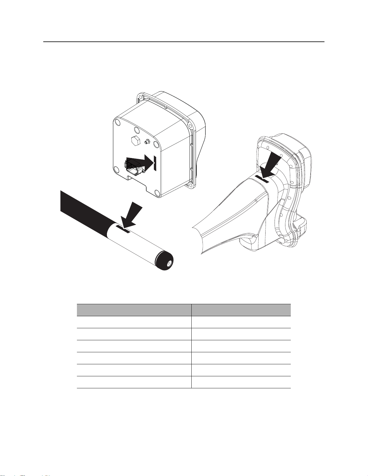
Serial Number Location
Record serial numbers and date of purchase in spaces provided. Serial numbers are located as shown
and displayed briefly in lower left corner of tracker and display screens when units are first powered up.
e17om048w.eps
CMW
Item
date of purchase:
tracker serial number:
display serial number:
beacon model and serial number:
beacon model and serial number:
beacon model and serial number:
Page 4

TK Series Guidance System Operator’s Manual Overview - 3
System Components
System Components
TK Tracker
Tracker Available Transmitter Frequencies Telemetry Radio
TK 29kHz
TKD 29kHz, 12kHz
TKQ 29kHz, 12kHz, 20kHz, 1.5kHz
Bluetooth
Bluetooth®, UHF Long Range
Bluetooth®, UHF Long Range
®
TX Transmitter
Transmitter Available Transmitter Frequencies Pitch Resolution Output Power
TX 29kHz 1% Low
TXH 29kHz 1% High
TXQ 29kHz, 12kHz, 20kHz, 1.5kHz 1% Configurable
TXQG 29kHz, 12kHz, 20kHz, 1.5kHz 0.1% Configurable
TK Trackers are compatible with Ditch Witch 86B series beacons: 86B, 86Bv2, 88B, and 88BAT. However,
for the best performance use a TX series transmitter.
TD Remote Display
Remote Display Mounting Options
TD In dash
TDR On-dash, magnetic
TD Displays are compatible with a Ditch Witch 8500TK tracker of the same region/country model.
CMW
Page 5

Overview - 4 TK Series Guidance System Operator’s Manual
Intended Use
Intended Use
The TK Series guidance system consists of a TK tracker, a TD display, and a TX series beacon transmitter.
The system provides the location of the transmitter to a depth of 110’ (33.53 m). The system provides
projected depth information and offers a Drill-To guidance mode. The system can track critical grade bores
when using a TXQG transmitter.
The system is designed for operation in temperatures typically experienced in earth moving and
construction work environments. Use in any other way is considered contrary to the intended use. The TK
Series guidance system should be operated only by persons familiar with its particular characteristics and
acquainted with the relevant safety procedures. The system should be serviced only by Ditch Witch
Electronics repair centers.
FCC Statement - Internal Transmitter
TK Series Tracker
FCC ID: ITQ-TK
IC: 3598A-TK
TK Series Display
Contains FCC ID: QOQWT41
Contains IC: 5213A-BGTWT41
TK Series Beacon
Contains FCC ID: QOQWT12
Contains IC: 5213A-BGTWT12A
Changes or modifications not expressly approved by the party responsible for compliance could void the
user’s authority to operate the equipment.
CMW
Page 6

TK Series Guidance System Operator’s Manual Overview - 5
RF Exposure Statement
RF Exposure Statement
In order to comply with RF exposure requirements during normal operation, this device must be held in
front of the body horizontally. The antenna must be vertical in line with the body with at least 4” (100 mm)
separation distance from the body.
Note: This equipment has been tested and found to comply with the limits for a Class B digital device,
pursuant to Part 15 of the FCC rules. These limits are designed to provide reasonable protection against
harmful interference in a residential installation. This equipment generates, uses and can radiate radio
frequency energy and, if not installed and used in accordance with the instructions, may cause harmful
interference to radio communications. However, there is no guarantee that interference will not occur in a
particular installation. If this equipment does cause harmful interference to radio or television reception,
which can be determined by turning the equipment off and on, the user is encouraged to try to correct the
interference by one or more of the following measures:
• Reorient or relocate the receiving antenna.
• Increase the separation between the equipment and receiver.
• Connect the equipment into an outlet on a circuit different from that to which the receiver is connected.
• Consult the dealer or an experienced radio/TV technician for help.
This device complies with Health Canada’s Safety Code. The installer of this device should ensure that RF
radiation is not emitted in excess of the Health Canada’s requirement. Information can be obtained at
http://hc-sc.qc.ca/ewh-sem/pub/radiation/radio_guide-lignes_direct-eng.php.
About This Manual
This manual contains information for the proper use of this equipment. Cross references such as “See
page 50” will direct you to detailed procedures.
Bulleted Lists
Bulleted lists provide helpful or important information or contain procedures that do not have to be
performed in a specific order.
Numbered Lists
Numbered lists contain illustration callouts or list steps that must be performed in order.
CMW
Page 7

Overview - 6 TK Series Guidance System Operator’s Manual
About This Manual
CMW
Page 8

TK Series Guidance System Operator’s Manual Foreword - 7
Foreword
This manual is an important part of your equipment. It provides safety information and operation
instructions to help you use and maintain your Ditch Witch equipment.
Read this manual before using your equipment. Keep it with the equipment at all times for future reference.
If you sell your equipment, be sure to give this manual to the new owner.
If you need a replacement copy, contact your Ditch Witch dealer. If you need assistance in locating a
dealer, visit our website at www.ditchwitch.com or write to the following address:
The Charles Machine Works, Inc.
Attn: Marketing Department
PO Box 66
Perry, OK 73077-0066
USA
The descriptions and specifications in this manual are subject to change without notice. The Charles
Machine Works, Inc. reserves the right to improve equipment. Some product improvements may have
taken place after this manual was published. For the latest information on Ditch Witch equipment, see your
Ditch Witch dealer.
Thank you for buying and using Ditch Witch equipment.
CMW
Page 9

Foreword - 8 TK Series Guidance System Operator’s Manual
TK Series Guidance System
Operator’s Manual
Issue number 1.0/OM-01/13
Part number 053-2594
Copyright 2013
by The Charles Machine Works, Inc.
, Ditch Witch, and CMW are registered trademarks of The Charles Machine
Works, Inc.
This product is covered by one or more of the following patents: 5794719, 5872703, 5880680, 7000710,
7251567, 7331409, 7786731, GB2439495, UK0846841, and other US and foreign patents pending.
CMW
Page 10
TK Series Guidance System Operator’s Manual Contents - 9
Contents
Overview
machine serial number, information about the type of work this machine is designed
to perform, basic machine components, and how to use this manual
Foreword
part number, revision level, and publication date of this manual, and factory contact
information
Safety
machine safety alerts and emergency procedures
Controls
machine controls and how to use them
System Operation
procedures for tracking beacon signals
Service
service intervals and instructions for this machine
Specifications
machine specifications including weights and measurements
1
7
11
15
33
47
51
Support
the warranty policy for this machine, and procedures for obtaining warranty
consideration and training
57
CMW
Page 11

Contents - 10 TK Series Guidance System Operator’s Manual
CMW
Page 12

TK Series Operator’s Manual Safety - 11
Safety
Chapter Contents
Guidelines . . . . . . . . . . . . . . . . . . . . . . . . . . . . . . . . 12
Safety Alert Classifications . . . . . . . . . . . . . . . . . . 13
Safety Alerts . . . . . . . . . . . . . . . . . . . . . . . . . . . . . . 14
CMW
Page 13

Safety - 12 TK Series Operator’s Manual
Guidelines
Guidelines
Follow these guidelines before operating any jobsite equipment:
• Complete proper training and read operator’s manual before using equipment.
• Contact One-Call (888-258-0808) and any utility companies which do not subscribe to One-Call. Have
all underground pipes and cables located and marked before operating equipment. If you damage a
utility, contact utility company.
• Classify jobsite based on its hazards and use correct tools and machinery, safety equipment, and work
methods for jobsite.
• Mark jobsite clearly and keep spectators away.
• Wear personal protective equipment.
• Review jobsite hazards, safety and emergency procedures, and individual responsibilities with all
personnel before work begins.
• Replace missing or damaged safety signs.
• Use equipment carefully. Stop operation and investigate anything that does not look or feel right.
• Contact your equipment dealer if you have any question about operation, maintenance, or equipment
use.
CMW
Page 14
TK Series Operator’s Manual Safety - 13
Safety Alert Classifications
Safety Alert Classifications
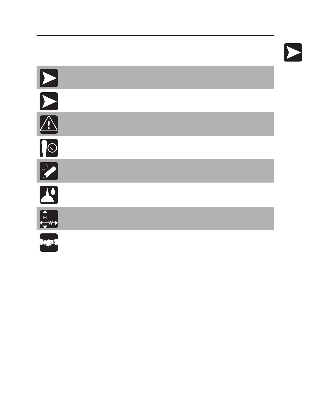
These classifications and the icons defined on the following pages work together to alert you to situations
which could be harmful to you, jobsite bystanders or your equipment. When you see these words and
icons in the book or on the unit, carefully read and follow all instructions. YOUR SAFETY IS AT STAKE.
Watch for the three safety alert levels: DANGER, WARNING and CAUTION. Learn what each level
means.
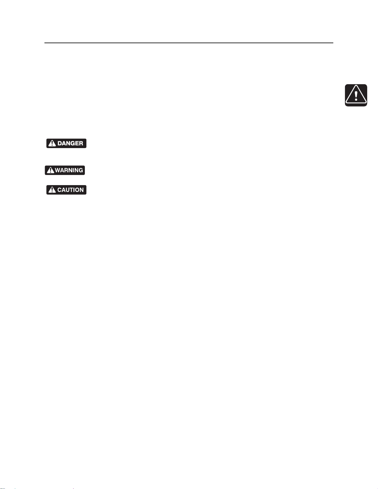
indicates a hazardous situation that, if not avoided, will result in death or serious injury.
This signal word is to be limited to the most extreme situations.
indicates a hazardous situation that, if not avoided, could result in death or serious injury.
indicates a hazardous situation that, if not avoided, could result in minor or moderate
injury.
Watch for two other words: NOTICE and IMPORTANT.
NOTICE indicates information considered important, but not hazard-related (e.g., messages relating to
property damage).
IMPORTANT can help you do a better job or make your job easier in some way.
CMW
Page 15
Safety - 14 TK Series Operator’s Manual
Safety Alerts
Safety Alerts
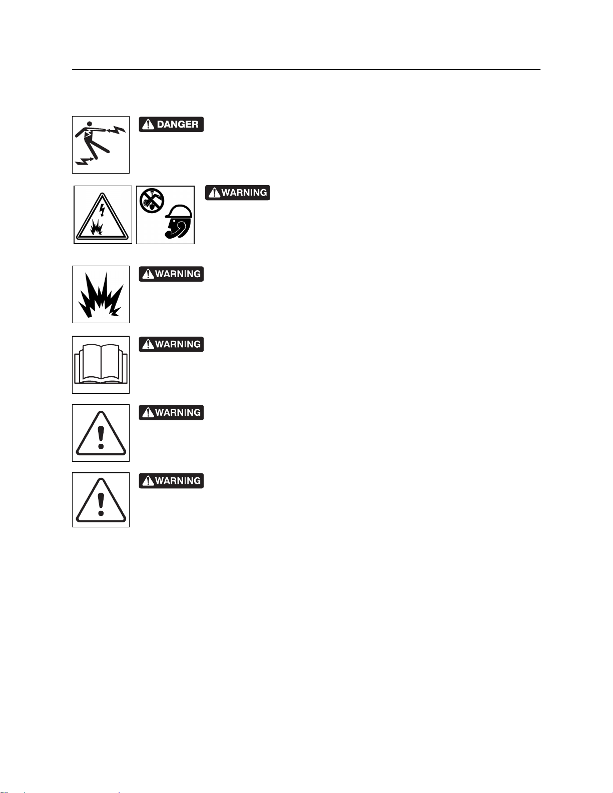
Electric shock. Contacting electric lines will cause death or serious injury.
Know location of lines and stay away.
Jobsite hazards could cause death or serious injury. Use
correct equipment and work methods. Use and maintain proper safety
equipment.
Explosion possible. Serious injury or equipment damage could occur.
Follow directions carefully.
Incorrect procedures could result in death, injury, or property damage.
Learn to use equipment correctly.
Moving traffic - hazardous situation. Death or serious injury could result.
Avoid moving vehicles, wear high visibility clothing, post appropriate warning signs.
Potential radio frequency (RF) hazard. Operating this device within 4” (100
mm) of your body may cause RF exposure levels to exceed FCC RF exposure limits and
should be avoided.
CMW
Page 16

TK Series Guidance System Operator’s Manual Controls - 15
Controls
Chapter Contents
TK, TKD, TKQ . . . . . . . . . . . . . . . . . . . . . . . . . . . . . 16
• Tracker Status Icons . . . . . . . . . . . . . . . . . . . . . . . . . . . . . . . . . . . . . . 16
• Beacon Status Icons. . . . . . . . . . . . . . . . . . . . . . . . . . . . . . . . . . . . . . . 18
• Buttons . . . . . . . . . . . . . . . . . . . . . . . . . . . . . . . . . . . . . . . . . . . . . . . . . 20
• Menus . . . . . . . . . . . . . . . . . . . . . . . . . . . . . . . . . . . . . . . . . . . . . . . . . 21
TD . . . . . . . . . . . . . . . . . . . . . . . . . . . . . . . . . . . . . . 24
• Display Status Icons . . . . . . . . . . . . . . . . . . . . . . . . . . . . . . . . . . . . . . . 24
• Beacon Status Icons. . . . . . . . . . . . . . . . . . . . . . . . . . . . . . . . . . . . . . . 25
• Buttons . . . . . . . . . . . . . . . . . . . . . . . . . . . . . . . . . . . . . . . . . . . . . . . . . 27
• Menus . . . . . . . . . . . . . . . . . . . . . . . . . . . . . . . . . . . . . . . . . . . . . . . . . 29
TX, TXH, TXQ, TXQG. . . . . . . . . . . . . . . . . . . . . . . . 31
CMW
Page 17
Controls - 16 TK Series Guidance System Operator’s Manual
TK, TKD, TKQ
TK, TKD, TKQ
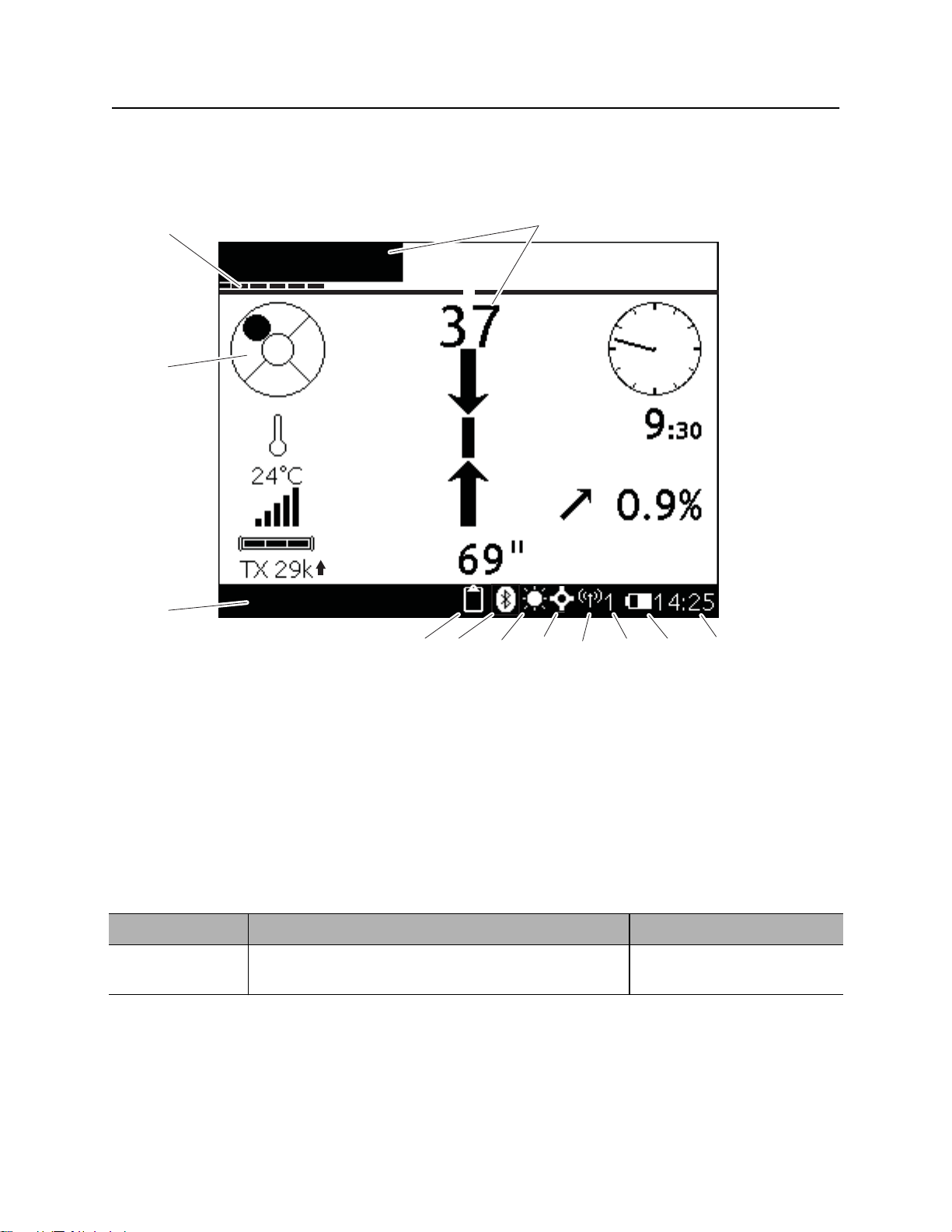
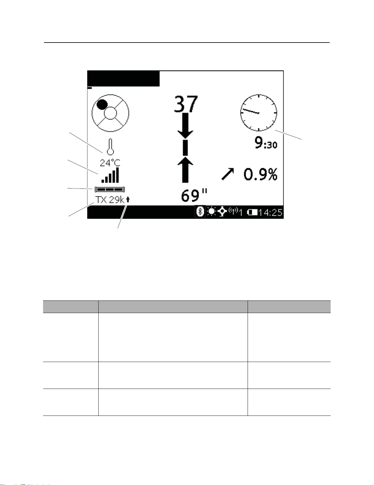
Tracker Status Icons
2
1
3
4
5
6 7 8 9 10 11 12
e17om001w.eps
1. Signal bar/number
2. Fine gain/Course gain
3. Bubble level
4. Message display
5. Logging indicator
6. Bluetooth connection indicator
Item Description Notes
1. Signal
strength
Shows signal strength in both bar and numerical
form.
7. Backlight indicator
8. Location active indicator
9. Telemetry indicator
10. Telemetry channel
11. Tracker battery indicator
12. Clock
CMW
Page 18

TK Series Guidance System Operator’s Manual Controls - 17
TK, TKD, TKQ
Item Description Notes
2. Fine gain
Course gain
3. Bubble level Indicates horizontal and vertical tilt of tracker.
4. Message
display
5. Logging
indicator
6. Bluetooth
connection
indicator
7. Backlight
indicator
8. Location
active
indicator
Shows fine gain as a 10-segment bar. Press up arrow or down
Shows course gain as a 2-segment bar:
• One bar displayed indicates shallow mode.
• Two bars displayed indicates deep mode.
Displays information such as software version,
logging status, beacon temperature warning, and low
battery alert.
Lights when logging function is active.
Lights when Bluetooth connection is established.
Lights when backlight is on. To improve battery life, turn
Lights when tracker is connected to a GPS device
via Bluetooth wireless technology.
arrow to adjust signal gain.
To change from shallow
mode to deep mode, adjust
fine gain.
off the backlight. See
“Settings Menu” on page 22.
9. Telemetry
indicator
10. Telemetry
channel
11. Tracker
battery
indicator
12. Clock Displays time. To set time, see “System
Indicates tracker is transmitting signal.
Displays telemetry channel selection.
Indicates amount of battery power remaining for the
tracker.
Menu” on page 23.
CMW
Page 19
Controls - 18 TK Series Guidance System Operator’s Manual
TK, TKD, TKQ
Beacon Status Icons
1
6
2
3
4
5
e17om002w.eps
1. Beacon temperature indicator
2. Beacon signal indicators
3. Beacon battery indicator
Item Description Notes
1. Beacon
temperature
indicator
2. Beacon
signal
indicators
Displays beacon temperature. Operating
temperature is between -04°F (-20°C) and 176°F
(80°C).
Icon darkens as temperature rises and temperature
is displayed numerically below the icon.
Shows strength of beacon signal received by tracker.
4. Beacon frequency indicator
5. Beacon mode indicator
6. Beacon roll indicator
IMPORTANT: An audible
warning is activated when
beacon temperature is
above 160°F (72°C).
3. Beacon
battery life
indicator
CMW
Graphically indicates battery life remaining.
Page 20

TK Series Guidance System Operator’s Manual Controls - 19
TK, TKD, TKQ
Item Description Notes
4. Beacon
frequency
indicator
5. Beacon
mode
indicator
6. Beacon roll
indicator
Displays active beacon frequency.
Up or down arrow indicates if beacon is active in Up
mode or Down mode.
“?” indicates beacon mode is not known and beacon
depth readings could be inaccurate.
Indicates beacon roll position in degrees, minutes or
hours.
See “Program Beacon” on
page 35 and “Select
Beacon Mode” on page 36.
CMW
Page 21

Controls - 20 TK Series Guidance System Operator’s Manual
TK, TKD, TKQ
Buttons
1234
e17om005w.eps
1. Select/Send
2. Down
Item Description Notes
1. Select/Send In Menu Mode, press to select item shown on
screen.
In Tracking Mode, press to send depth to remote
display.
2. Down In Menu Mode, press to move selection down.
In Tracking Mode, press to decrease signal gain.
3. Up In Menu Mode, press to move selection up.
In Tracking Mode, press to increase signal gain.
4. Power/Menu To turn unit on, press once.
To turn unit off, press for 2 seconds.
3. Up
4. Power/Menu
CMW
To access menu or return to a previous menu,
press less than 2 seconds.
Page 22

TK Series Guidance System Operator’s Manual Controls - 21
TK, TKD, TKQ
Menus
Beacon Menu
Description Notes
Calibrate Depth Sets built-in adjustment of tracker-to-beacon communication to provide
accurate depth measurements.
Frequency Sets tracker receiving frequency. Available settings: TX1.5K, TX12K, TX20K,
TX29K, 86B 12K, 86B 29K.
Calibrate Roll Sets roll position for beacon equivalent to bit pointing up (12 o’clock, 0
minutes, 0°).
Calibrate Pitch Sets 0.0% pitch position for grade beacon (1.0% limit).
Configuration Shows TX series beacon Bluetooth devices available for connection. After
connection, shows beacon data.
Sets the operating modes of configurable beacons.
Arrow Lock Adjusts the range at which the locate arrows lock onto the beacon signal.
Select the default setting for shallow bores, use Wide for deep bores, and
Widest for extreme cases.
Wireless Menu
Description Notes
Telemetry Selects or disables telemetry mode.
Available settings: off, Bluetooth, Long Range (TKD or TKQ only)
Channel Sets telemetry channel when using UHF Long Range radio for telemetry.
Available settings: 1 (default) through 15
Bluetooth Scans for and manage Bluetooth device connections.
Tracker Control Enables or disables thrust and rotation of drilling unit.
Available settings: Disable Rig (default), Enable Rig.
Tracker Control
code
Selects code for Tracker Control feature corresponding to code on TD
display.
Note: The number of available channels will vary based on region or
country configuration.
CMW
Page 23

Controls - 22 TK Series Guidance System Operator’s Manual
TK, TKD, TKQ
Settings Menu
Description Notes
Language Selects user interface language.
Units Selects the units for displaying temperature, distance, pitch and roll.
Backlight Selects backlight setting. Available settings: Off, On, or Auto.
Note: To save battery life, operate with backlight off when possible.
Clock Sets the system time.
Volume Controls volume of the signal audio volume level.
Available settings: mute, low, high (default).
IMPORTANT: Beacon temperature warning is always audible.
Auto Power Off Enables or disables a five-minute inactivity shutdown.
Available settings: enabled (default), disabled.
Logging Menu
Description Notes
Logging Mode Selects or disables the logging mode.
Available settings: disable, manual, auto-log
New Log Creates a new log file.
Log Manager Manages log files. Available settings: select, view, send, send as 750, or
delete.
TMS Plus Connects to TMS Plus software.
Delete All Logs Deletes all log files stored on the tracker.
Delete Last
Pipe
Deletes the last point information from the current log file.
CMW
Page 24

TK Series Guidance System Operator’s Manual Controls - 23
TK, TKD, TKQ
System Menu
Description Notes
About Lists hardware and software versions, serial number, and copyright
information.
Diagnostics Displays troubleshooting and diagnostic options.
Software
Update
Analyzer Launches the Bore Path Analyzer.
Launches a software update.
CMW
Page 25

Controls - 24 TK Series Guidance System Operator’s Manual
TD, TDR
TD, TDR
Display Status Icons
0.0%
12
7.0 ft
e17om038w.eps
1. Message display
2. Backlight indicator
3. Tracker signal
Item Description Notes
1. Message
display
2. Backlight
indicator
3. Tracker
signal
strength
12345
4. Telemetry channel
5. Clock
Displays information such as software version,
logging status, beacon temperature warning, and low
battery alert.
Shows if backlight is on. See “Settings Menu” on
page 29.
Indicates strength of tracker radio signal received by
display.
White bars indicate good
reception; hollow or black
bars indicate poor
reception.
4. Telemetry
channel
5. Clock Displays time.
CMW
Displays telemetry channel selection.
Page 26

TK Series Guidance System Operator’s Manual Controls - 25
TD, TDR
Beacon Status Icons
4
3
2
1
e17om039w.eps
1. Beacon battery life
0.0%
12
5
7.0 ft
4. Beacon roll indicator
2. Beacon temperature
3. Beacon pitch
Item Description Notes
1. Beacon
battery life
2. Beacon
temperature
3. Beacon
pitch
4. Beacon roll
indicator
Graphically indicates battery life remaining.
Displays beacon temperature.
Icon darkens as temperature rises and temperature is
displayed numerically below the icon.
Displays pitch of beacon in percent grade or degrees.
The arrow behind the value indicates whether pitch is
positive or negative.
Graphically and numerically indicates beacon’s roll
position.
5. Beacon depth measurement
CMW
Page 27

Controls - 26 TK Series Guidance System Operator’s Manual
TD, TDR
Item Description Notes
5. Beacon
depth
Displays beacon depth received from tracker.
CMW
Page 28

TK Series Guidance System Operator’s Manual Controls - 27
TD, TDR
Buttons
1234
e17om040w.eps
1. Select/Send
2. Down
Item Description Notes
1. Select/Send Press to select item shown on screen.
When connected to TMS Plus or OGMS: Press to
send data for current pipe to TMS Plus or OGMS.
2. Down In Tracking Mode, press to delete the last stored pipe
information.
In Menu Mode, press to move selection down.
3. Up In Tracking Mode, press to recall the last stored pipe
information or to query the next pipe data from TMS
Plus.
In Menu Mode, press to move selection up.
3. Up
4. Power/Menu
CMW
Page 29

Controls - 28 TK Series Guidance System Operator’s Manual
TD, TDR
Item Description Notes
4. Power/Menu To turn on, press once.
To turn off, press for 2 seconds.
Press button less than 2 seconds to access menu.
Press at any time to return to previous menu.
CMW
Page 30

TK Series Guidance System Operator’s Manual Controls - 29
TD, TDR
Menus
Logging Menu
Description Notes
Logging
Mode
New Log Creates a new log file.
Log Manager Manages log files.
TMS Plus Accesses TMS Plus tracking software.
Delete All
Logs
Delete Last
Pipe
Selects or disables the logging mode.
Available settings: disable, manual, auto-log
Available settings: select, send, send as 750, or delete
Available options: Download All, Connect.
Deletes all log files stored on the tracker.
Deletes the last point information from the current log file.
Wireless Menu
Description Notes
Telemetry Selects or disables telemetry mode.
Available settings: Long Range, Bluetooth, 8500TK.
Channel Sets telemetry channel when using UHF Long Range radio for telemetry.
Available settings: 1 (default) through 15
Bluetooth Scans for and manages Bluetooth device connections.
Tracker
Control
Displays control code to pair with tracker to enable or disable thrust and rotation
of drilling unit.
Settings Menu
Description Notes
Language Controls user interface language.
Units Selects the units for displaying temperature, distance, pitch and roll.
Note: The number of available channels will vary based on region or
country configuration.
CMW
Page 31

Controls - 30 TK Series Guidance System Operator’s Manual
TD, TDR
Description Notes
Backlight Selects backlight setting. Available settings: Off, On, or Auto
Note: To save battery life, operate with backlight off when possible.
Clock Sets the system time.
System Menu
Description Notes
About Lists hardware and software versions, serial number, and copyright
information.
Diagnostic Displays troubleshooting and diagnostic options.
Software
Update
Launches a software update. Options: Continue, Cancel.
CMW
Page 32

TK Series Guidance System Operator’s Manual Controls - 31
TX, TXH, TXQ, TXQG
TX, TXH, TXQ, TXQG
1
e17om047w.eps
1. Battery compartment 2. Isolator
1. Battery
compartment
2. Isolator Used to determine UP or DOWN operating mode
Contains one of the following battery options:
• Ditch Witch Power Stick
(p/n 222-1369)
• one lithium CC battery
2
CMW
Page 33

Controls - 32 TK Series Guidance System Operator’s Manual
TX, TXH, TXQ, TXQG
CMW
Page 34

TK Series Guidance System Operator’s Manual System Operation - 33
System Operation
Chapter Contents
Tracking Overview . . . . . . . . . . . . . . . . . . . . . . . . . 34
Setup . . . . . . . . . . . . . . . . . . . . . . . . . . . . . . . . . . . . 35
• Analyze Bore Path (TXQ and TXQG) . . . . . . . . . . . . . . . . . . . . . . . . . . 35
• Program Beacon (TXQ and TXQG) . . . . . . . . . . . . . . . . . . . . . . . . . . . 35
• Activate Beacon . . . . . . . . . . . . . . . . . . . . . . . . . . . . . . . . . . . . . . . . . . 36
• Install Beacon into Tool Housing. . . . . . . . . . . . . . . . . . . . . . . . . . . . . . 36
• Calibrate Tracker to Beacon . . . . . . . . . . . . . . . . . . . . . . . . . . . . . . . . . 37
Enable Tracker Control . . . . . . . . . . . . . . . . . . . . . 39
Locate . . . . . . . . . . . . . . . . . . . . . . . . . . . . . . . . . . . 40
• Walkover Location Mode. . . . . . . . . . . . . . . . . . . . . . . . . . . . . . . . . . . . 40
• Drill-To Location Mode . . . . . . . . . . . . . . . . . . . . . . . . . . . . . . . . . . . . . 42
Log Data . . . . . . . . . . . . . . . . . . . . . . . . . . . . . . . . . 44
Transfer Data. . . . . . . . . . . . . . . . . . . . . . . . . . . . . . 45
CMW
Page 35

System Operation - 34 TK Series Guidance System Operator’s Manual
A
A
Tracking Overview
Tracking Overview
The Ditch Witch® TK Series Guidance
System is designed to function with
horizontal directional drilling units. The
system is composed of three components:
beacon transmitter, tracking unit, and
display unit.
TX, TXH, TXQ, and TXQG beacons
transmit roll angle, beacon temperature, beacon battery status, and pitch information and perform best in
Ditch Witch approved tool housings.
TK trackers detect beacon transmission and relay data to TD displays onboard the drilling unit. The
tracking data can be logged and transferred to tracking software.
TX series beacons emit a dipole magnetic field
that can be used multiple ways to determine
beacon position. The beacon is always located at
peak signal strength between two null points (also
known as ghost signals). The peak signal strength
region (B) is located directly over the beacon. The
two null point regions (A) are located in front of
and behind the beacon.
If the TK tracker is in one of the null point regions,
the null point icon (A) will be displayed with fore/
aft and/or left/right arrow showing the direction to
move the tracker to the null point.
If the tracker is in the peak signal strength region,
the beacon icon (B) will be displayed as well as a
fore/aft arrow to guide the tracker over the plane
perpendicular to the beacon axis.
When the beacon has been correctly located, the
depth reading is displayed.
A
e17om043w.eps
e17om045w.eps
A
B
CMW
Page 36

TK Series Guidance System Operator’s Manual System Operation - 35
Setup
Setup
Potential radio frequency (RF) hazard. Operating this device within 4”
(100 mm) of your body may cause RF exposure levels to exceed FCC RF exposure limits
and should be avoided.
To help avoid injury, this device must not be co-located with any other radio transmitter.
Analyze Bore Path (TKD and TKQ)
The Bore Path Analyzer analyzes active interference (noise) along the bore path and recommends
frequencies that will ensure the best communication for accurate depth and location. Active interference is
any magnetic field generated by a source other than the beacon, such as power lines, traffic loops, cable
TV, and phone lines that decreases the communication range of the tracker. This feature does not analyze
passive interference (fences, metal pipe, and vehicles), which distorts the signal and shape of the beacon
dipole field, and thus distorts location and depth.
1. Ensure that no active beacons are operating in the area.
2. Place the TK tracker at the position where the bore will be started.
3. Navigate to System>Analyzer
4. To clear any previous readings, press and hold the Select/Send button.
5. Press the Select/Send button. Tracker will analyze frequency noise at that position.
6. Move tracker to next position along the intended bore path.
7. Repeat steps 3 and 4 until a full noise plot is recorded.
8. At the end of the bore path, press the Menu button to display the recommended beacon frequency.
Program Beacon (TXQ and TXQ)
1. On the TK tracker, navigate to Beacon>Configuration.
2. Scan for available devices, then select a beacon to connect. Once connected, view the beacon
information screen, noting the settings for UP mode and DOWN mode.
3. Select Set Modes and follow prompts to program frequency and power level for UP and DOWN
modes.
CMW
Page 37

System Operation - 36 TK Series Guidance System Operator’s Manual
Setup
Activate Beacon
Activate beacon by tightening battery cap and rolling it clockwise two times.
Beacon will deactivate (sleep) after 20 minutes of inactivity. To force deactivation, set the beacon to the 5
o’clock roll position and wait 5 minutes.
Select Beacon Mode (TXQ and TXQG)
Incorrect procedures could result in death, injury, or property damage.
Learn to use equipment correctly.
To help avoid injury, learn to monitor the beacon mode indicator (see page 18). If the tracker is unsure
of the beacon mode, a “?” will be displayed to warn the operator that depth shown could be inaccurate.
TXQ and TXQG multiple frequency beacons are capable of transmitting at multiple frequency/power
levels; however, only two frequency/power combinations can be stored to the beacon at one time. This
creates two operation modes: UP and DOWN.
Select UP Mode:
1. Loosen battery cap.
2. Hold beacon parallel to the ground with the flat
of the isolator (shown) facing up.
3. Tighten cap, keeping beacon steady.
Select DOWN Mode:
1. Loosen battery cap.
2. Hold beacon parallel to the ground with the flat
of the isolator facing down.
3. Tighten cap, keeping beacon steady.
Change Mode Downhole
To change mode downhole, allow beacon to go into sleep mode, then wake beacon within 1 minute.
e17om041w.eps
Install Beacon into Tool Housing
IMPORTANT: Check beacon operation and condition of both isolators before installing beacon into tool
housing.
1. Place beacon into tool housing with flat top of isolator toward bit, facing up.
2. Check for proper beacon alignment by rolling housing on the ground and watching for corresponding
roll positions on tracker display.
CMW
Page 38

TK Series Guidance System Operator’s Manual System Operation - 37
Setup
Calibrate Tracker to Beacon
Manual Method
TX and TXH beacons have one-way communication with the tracker. To accurately scale depth, calibrate
the tracker to the beacon.
1. Activate beacon and place on ground exactly
10 ft (305 cm) from tracker, as shown.
2. Position tracker parallel to center of beacon.
3. Select Beacon>Calibrate Depth and follow
prompts.
IMPORTANT: If using a multi-frequency
86 Series beacon or a multi-mode TX
series beacon, calibrate each frequency
separately.
Bluetooth Method
TXQ and TXQG beacons utilize Bluetooth radios
for two-way communication with the tracker. Once
the tracker is paired to the beacon, calibration
takes place automatically. To pair the tracker with
the beacon:
1. Activate the beacon.
2. On the tracker, go to Wireless>Bluetooth.
Select the correct TX_0000 beacon to create a connection.
3. Select Beacon>Calibrate Depth and follow prompts. This step will calibrate both UP and DOWN
modes.
e17om051w.eps
CMW
Page 39

System Operation - 38 TK Series Guidance System Operator’s Manual
Setup
Roll and Pitch Calibration
Roll calibration is only necessary if using a TX beacon in a non-standard housing. To calibrate roll, install
beacon into housing, navigate TK tracker to Beacon>Calibrate Roll and follow prompts.
Pitch calibration is only necessary when using a grade beacon (86G or TXQG). To calibrate pitch, install
beacon into housing and level housing to 0%. On the tracker, check the beacon pitch reading. If the
reading is a value other than zero, navigate to Beacon>Calibrate Pitch and follow prompts until the
tracker shows a pitch value of 0%.
Test Beacon Operation
Step approximately 15’ (4.57 m) from beacon. Turn on tracker, select frequency, check beacon mode, and
adjust gain so that signal strength is approximately 50%.
• Roll beacon and look at display for corresponding roll positions.
• Tilt beacon and look at display for corresponding pitch positions.
• Check beacon battery status and temperature.
CMW
Page 40

TK Series Guidance System Operator’s Manual System Operation - 39
Enable Tracker Control
Enable Tracker Control
Incorrect procedures could result in death, injury, or property damage.
Learn to use equipment correctly.
To help avoid injury, do not stand or walk over the bore path while drill string is moving
during drilling and backreaming.
Tracker Control allows the tracker operator to disable hydraulic thrust and rotation power to a compatible
Ditch Witch® drilling unit within 16 seconds. This mode will not stop thrust and rotation immediately.
When tracker and display communications cease, green tracker control strobe on drilling unit will light and
thrust and rotation will be disabled.
IMPORTANT:
• If thrust and rotation do not work, check if tracker control strobe on drilling unit is on.
If it is, communication has probably stopped between tracker and display or tracker
is set to incorrect code. If communication cannot be restored, install tracker control
key on drilling unit and turn to the Disable position to override tracker control.
Tracker control strobe will go off and thrust and rotation will function.
• Tracker operator cannot stop thrust and rotation from tracker with tracker control key
installed in drilling unit and turned to disable position.
• See the drilling unit operator manual for more information.
Operation
1. Turn on drilling unit, display, and tracker.
2. On display, navigate to Wireless>Telemetry>Control Code. Note code. (The code is the last four
digits of the display serial number.)
3. On tracker, navigate to Wireless>Telemetry>Control Code. Enter code from display using the Up
and Down arrows for each digit. Press Select/Send to save the desired number for each digit.
4. Remove tracker control key from drilling unit and keep in tracker operator’s possession.
5. On tracker, navigate to Wireless>Telemetry>Tracker Control. Select Enable.
6. Drill and track bore until drill head enters target pit or exits ground.
7. Turn off tracker. After 8-16 seconds, tracker control light on drilling unit will come on and hydraulic
power to thrust and rotation will be disabled.
8. Change downhole tools.
9. If you are tracking backreamer’s path, turn on tracker and enable code transmission. After 8-16
seconds, tracker control light on drilling unit will go off and thrust and rotation will function.
If you are not tracking backreamer’s path, install tracker control key on drilling unit and turn to the
Disable position to override tracker control. Tracker control light on drilling unit will go off and thrust
and rotation will function.
CMW
Page 41

System Operation - 40 TK Series Guidance System Operator’s Manual
Locate
Locate
The tracker has two modes: walkover location and drill-to. Use walkover location to find the position of the
beacon. Once the tracker is in or near the beacon plane, view the depth, pitch, and roll position. In drill-to
mode, the tracker is placed along the intended bore path and provides steering corrections for the drilling
unit operator to drill that path.
Walkover Location
1
3
e17om003w.eps
1. Locate arrows
2. Beacon pitch
Item Description Notes
1. Locate
arrows
2. Beacon
pitch
3. Beacon
Depth
Indicates direction to move tracker to locate beacon.
Displays pitch of beacon in percent grade or degrees.
Displays depth of beacon when beacon is properly
located.
3. Beacon depth
2
CMW
Page 42

TK Series Guidance System Operator’s Manual System Operation - 41
Locate
Incorrect procedures could result in death, injury, or property damage.
Learn to use equipment correctly.
To help avoid injury, do not stand or walk over the bore path while drill string is moving
(during drilling and backreaming).
NOTICE: High temperature is the primary cause of beacon failure. Monitor beacon temperature
carefully.
• If temperature goes above 160°F (70°C), stop drilling, pull back 3’ (.9 m), and pump fluid into
hole until beacon cools.
• Operating beacon at temperatures above 176°F (80°C) will cause beacon overheating and
failure and will void beacon warranty. Monitor beacon temperature carefully.
• Operating fluid-assisted drilling system without proper fluid flow will cause overheating and
damage to beacon and tool head.
Peak Location
1. Walk bore path with bottom of tracker parallel to beacon. Do not hold tracker at right angle to beacon.
2. Move until beacon icon is shown and both fore/aft arrows are shown. Sweep tracker from side to side
and use signal strength display to find lateral location of beacon. The beacon is located at the point
where the signal strength number is the highest and the bar graph indicator is highest.
3. Step back until null point icon is shown and sweep tracker side to side until both left/right arrows are
on.
4. Move forward until beacon icon is shown and both fore/aft arrows are lit.
5. Press the Select/Send button to log depth estimate. Mark location.
Null Point Location
1. Starting from behind the beacon, walk until the null point icon is displayed. Follow arrows and minimize
signal strength to find and mark the null point.
2. Walk forward through the beacon region and into the opposite null point region. Find and mark the null
point.
3. Walk backwards along the line connecting the two null points until the beacon icon is displayed and
fore/aft arrows are lit.
4. Press the Select/Send button to log depth estimate. Mark location.
CMW
Page 43

System Operation - 42 TK Series Guidance System Operator’s Manual
Locate
Drill-To Location Mode
1
2
3
4
5
e17om004w.eps
1. Steering arrow
2. Horizontal distance
3. Beacon pitch
Item Description Notes
1. Steering
arrow
2. Horizontal
distance
3. Beacon
pitch
4. Projected
depth
Indicates which direction the operator needs to
move to correctly align with the tracker.
Displays horizontal distance from the tracker
antenna to a point directly above the beacon.
Displays pitch of beacon in percent grade or
degrees. The orientation of the arrow indicates
whether the pitch is positive or negative.
Displays projected depth directly below the tracker
antenna assuming the beacon proceeds at its
current pitch reading.
4. Projected depth
5. Current depth
If the tool head is directly in
line with the tracker, the
arrow will become a
diamond.
5. Current
depth
CMW
Displays current depth of the beacon from the
tracker antenna assuming flat terrain.
Page 44

TK Series Guidance System Operator’s Manual System Operation - 43
Locate
Procedure
Incorrect procedures could result in death, injury, or property damage.
Learn to use equipment correctly.
To help avoid injury:
• If location and depth are critical, confirm by hand-digging.
• Do not stand or walk over the bore path while drill string is moving (during drilling and backreaming).
1. Place tracker in tracker stand along intended bore path with the battery caps facing toward the rig. Use
the bubble level to ensure tracker is positioned correctly.
2. Drill as usual. Use the TD to monitor steering arrows, current depth, horizontal distance, and projected
depth.
IMPORTANT:
• The tracker must be kept in front of the beacon and above the beacon. The beacon must
be projecting below the tracker to give correct results.
• If the distance between the tracker and the beacon is greater than 35’ (11.7 m) a radial
distance estimate and steering correction arrow will be displayed.
• Doubleclick the Select/Send button to switch between walkover and drill-to modes.
Steer
The steering arrow displays the correction
required to guide the beacon back to the bore
path defined by the tracker’s location and
orientation.
CMW
Page 45

System Operation - 44 TK Series Guidance System Operator’s Manual
Finish Locating
Finish Locating
When location is complete, remove beacon from tool housing before mud in beacon chamber hardens and
seizes beacon into housing.
1. Remove beacon from tool housing.
IMPORTANT: If beacon will not come out, do not use force. Try soaking housing in water until
dried mud inside housing softens. If beacon still will not come out, contact your Ditch Witch
dealer for advice.
2. Clean beacon and remove battery.
3. Wash and lubricate tool housing.
Log Data
Tracking data can be saved to a file on the tracker or the display and transferred directly to a personal
computer with TSR or TMS PLUS software.
1. Select file to save data:
To create a new log file, navigate to Logging>New Log.
To add data to an existing log file, navigate to Logging>Log Manager.
Note: All data will be stored to the selected log file until another log file is selected or until logging is
disabled.
2. Log data along bore path using Auto-Log or Manual log.
TK TD
Auto-Log Pipe is logged when the Select/
Send button is pressed to send
depth to display.
Manual log Pipe is logged after a depth has
been sent to the remote display and
the Up button is pressed while the
depth value is still highlighted.
3. When logging is complete, transfer data to a personal computer.
Pipe is logged when depth is received
from tracker. No user action is required.
Pipe is logged when depth has been
received from the tracker and the
Select/Send button is pressed.
CMW
Page 46

TK Series Guidance System Operator’s Manual System Operation - 45
Transfer Data
Transfer Data
Using TSR Software
1. Pair the tracker or display and the computer:
On the TK or TD, navigate to Wireless>Bluetooth and follow prompts.
Or, on the computer, use the “Add Device” option in the computer’s Bluetooth devices menu.
2. Enable the computer to receive files. This procedure varies by manufacturer, but is often done by
selecting “Receive File” from the Bluetooth icon in the computer task bar.
3. On the TK or TD, navigate to Logging>Log Manager, select the desired log file and press the Select/
Send button and follow prompts.
Using TMS Plus Software
Use the “Download” option to download log files from the TK or TD. When prompted by TMS Plus, select
the virtual COM port assigned to the TK or TD. This port number is stored in the Properties dialog in the
Bluetooth Devices folder.
Select Logging>TMS Plus>Download All and follow prompts to complete the download. See the TMS
Plus operation instructions for more information.
Using Connected Logging
The TD can also connect to the TMS Plus software application and transfer bore data in real time. The TD
button functions will change as follows during connected logging:
Button TMS Live Function
Select/Send Store/send last depth received from tracker.
Down arrow Delete last stored pipe
Up arrow Query next pipe information from TMS Plus.
CMW
Page 47

System Operation - 46 TK Series Guidance System Operator’s Manual
Transfer Data
CMW
Page 48

TK Series Guidance System Operator’s Manual Service - 47
Service
Chapter Contents
General Care . . . . . . . . . . . . . . . . . . . . . . . . . . . . . . 48
As Needed . . . . . . . . . . . . . . . . . . . . . . . . . . . . . . . 48
Update Software . . . . . . . . . . . . . . . . . . . . . . . . . . . 49
CMW
Page 49

Service - 48 TK Series Guidance System Operator’s Manual
General Care
General Care
Under normal operating conditions, tracking system components need only minor maintenance. Following
these care instructions can ensure longer equipment life:
• Do not drop the equipment.
• Do not expose the equipment to high heat (such as in the rear window of a vehicle).
• Clean equipment with a damp cloth and mild soap. Never use scouring powder.
• Do not immerse in any liquid.
• Inspect housing daily for cracks or other damage. If housing is damaged, contact your equipment
dealer for replacement.
• Do not mix new and used batteries.
• Remove battery if storing for an extended period.
As Needed
Change Batteries
Tracker
IMPORTANT: Do not mix new and used
batteries. Do not mix battery brands or
types.
Use four C-cell alkaline or rechargeable Ni-MH
batteries in tracker.
1. Remove battery caps.
2. Insert batteries as shown.
3. Install and tighten battery caps.
4. Check operation.
Beacon
Use one Lithium CC battery or one Power Stick battery (222-1369) in beacon.
1. Remove battery cap.
e17om044w.eps
2. Insert battery as shown.
3. Install and tighten battery cap.
4. Check operation.
CMW
Page 50

TK Series Guidance System Operator’s Manual Service - 49
Update Software
Update Software
Software updates are often available to fix issues, change software behavior, or add software features.
1. Obtain the software update file (TKxxxxxx.TSU for the TK or TDxxxxxx for the TD)
2. Copy the file to a device that supports the Bluetooth OBEX Object Push Profile, such as a computer.
3. Use the Wireless>Bluetooth menu to pair the device to the TK or TD unit. Or, use the device to
initiate the pairing process.
4. Navigate to System>Software Update and press the Select/Send button to launch the update
process.
5. Once the TK or TD indicates it is waiting for a file, begin the transfer from the sending device. A
progress bar will be displayed on the TK or TD and the unit will restart when the update is complete.
CMW
Page 51

Service - 50 TK Series Guidance System Operator’s Manual
Update Software
CMW
Page 52

TK Series Guidance System Operator’s Manual Specifications - 51
Specifications
Chapter Contents
TK Tracker. . . . . . . . . . . . . . . . . . . . . . . . . . . . . . . . 52
TD Display . . . . . . . . . . . . . . . . . . . . . . . . . . . . . . . . 54
TX Series Beacons . . . . . . . . . . . . . . . . . . . . . . . . . 55
CMW
Page 53

Specifications - 52 TK Series Guidance System Operator’s Manual
TK Series Tracker
TK Series Tracker
H
W
L
e17om049w.eps
Dimensions U.S. Metric
H Height 30” max 762 mm max
L Length 13” max 330 mm max
W Width 7” max 178 mm max
Operating weight 9 lb max 4.1 kg max
Environmental U.S. Metric
Operating temperature -4°F to 122°F -20°C to 50°C
Storage temperature -22°F to 158°F -30°C to 70°C
IP Rating IP65
CMW
Page 54

TK Series Guidance System Operator’s Manual Specifications - 53
TK Series Tracker
Performance U.S. Metric
TK Depth distance >70 ft w/ H power beacon >18.3 w/ H power beacon
Depth accuracy +/- 5% over testable range
Telemetry radio range 500 ft 152.4 m
TKD,
Depth distance >100 ft w/ H power beacon >30.5 w/ H power beacon
TKQ
Depth accuracy +/- 5% over testable range
Telemetry radio range 2000 ft 610 m
Batteries
Battery type C-cell alkaline or C-cell size NiMH rechargeable
Number of cells 4
Battery life 12 hours at room temperature
CMW
Page 55

Specifications - 54 TK Series Guidance System Operator’s Manual
Universal Display
Universal Display
WL
H
e17om050w.eps
Dimensions U.S. Metric
TDR
(remote version)
TD
(in-dash version)
Environmental U.S. Metric
Operating temperature -4°F to 140°F -20°C to 60°C
Storage temperature -22°F to 158°F -30°C to 70°C
IP Rating IP66
Performance U.S. Metric
Telemetry range: w/ TKD and TKQ 2000 ft 610 m
Length 6 in. max 152.4 mm max
Width 6 in. max 152.4 mm max
Depth 6 in. max 152.4 mm max
Length 7 in. max 177.8 mm max
Width 7 in. max 177.8 mm max
Depth 6.5 in. max 165.1 mm max
CMW
w/ TK 500 ft 152.4 m
Page 56

TK Series Guidance System Operator’s Manual Specifications - 55
TX Series Beacons
TX Series Beacons
Dimensions U.S. Metric
L Length 17.8 in. max 452 mm max
W Width 1.5 in. max 38 mm max
Operating weight
Environmental U.S. Metric
Maximum operating temperature 176°F max 80°C max
Maximum fluid pressure 60 psi max 4 bar max
IP Rating IP67
Performance
Telemetry Data
Pitch
(TXQG or grade
beacons)
Roll 24 positions (15°)
Depth
TX with TK 40 ft 12.2 m
with TKD and TKQ 60 ft 18.3 m
TXH with TK 70 ft 21.3 m
1% increments up to 100%
0.1% pitch resolution within 45% of level and 1% pitch resolution
Pitch communicated at a minimum rate of 1.5 seconds when a
high priority communication does not exist
Roll accuracy will be at least 5°, communicated at a minimum of
2.7 rolls per second. Settle time is to be no more than 1 second.
with TKD and TKQ 110 ft 33.5 m
Battery
Battery Types: Ditch Witch Power Stick (p/n 222-1369); Lithium ‘CC’ battery
CMW
Page 57

Specifications - 56 TK Series Guidance System Operator’s Manual
Battery
Battery life in a standard dirt housing: standard power, 60 hrs; H power, 16 hrs.
(Battery life may vary when using a TXQ or TXQG beacon configured to run at high power.)
CMW
Page 58

TK Series Guidance System Operator’s Manual Support - 57
Procedure
Support
Procedure
Notify your dealer immediately of any malfunction or failure of Ditch Witch Electronics equipment.
Always give model, serial number, and approximate date of your equipment purchase. This information
should be recorded and placed on file by the owner at the time of purchase.
Return damaged unit to dealer for inspection and warranty consideration if in warranty time frame.
All repairs must be done by an authorized Ditch Witch Electronics repair facility. Repairs done elsewhere
will void warranty.
Resources
Publications
Contact your Ditch Witch Electronics dealer for publications and videos covering safety, operation, service,
and repair of your equipment.
Training
For information about on-site, individualized training, contact your Ditch Witch Electronics dealer.
CMW
Page 59

Warranty - 58 TK Series Guidance System Operator’s Manual
Limited Product Warranty Policy
Warranty
Limited Product Warranty Policy
Warranty Periods
New Product
A twelve-month period starts on the date of delivery to the end user:
all trackers, remote displays, receivers, transmitters, radars, fault finders
A six-month period starts on the date of delivery to the end user:
all directional and locate beacons
A three-month period starts on the date of delivery to the end user:
all accessories: cables, clamps, canoes, bags, and adapters
Used Product (Cosmetics)
A three-month warranty starts on the date of delivery to the end user on used and refurbished products
sold from Ditch Witch Electronics dealers. Used products are non-returnable.
Service and Repair
A one-month warranty on labor starts on the date the unit is repaired, and a three-month warranty on parts
starts on the date the unit is repaired for all products.
Extended Warranty
The extended warranty may be purchased at the time the equipment is sold or anytime within the original
warranty period. The extension is for an additional twelve or twenty-four months, depending on extended
warranty purchased, for a total coverage of twenty-four to thirty-six months. Exclusions: All beacons and
accessories.
CMW
Page 60

TK Series Guidance System Operator’s Manual Warranty - 59
Limited Product Warranty Policy
Details and Exclusions
• The warranty includes only Ditch Witch Electronics products and accessories that are manufactured
and distributed by Ditch Witch Electronics. The warranty compensates on defects in material or
workmanship.
• Defects will be determined through inspection by The Charles Machine Works, Inc. or authorized
repair centers. Original purchaser must make the defective item available for inspection within 30 days
of the date the part fails.
• The warranty is limited to replacement of the defective part. The replacement part may be new or
remanufactured. Repair and installation of defective part will be at no charge when product or item is
delivered to The Charles Machine Works, Inc. or an authorized repair center. The product or item will
be returned at no charge for return freight.
• The warranty periods do not represent the useful life of Ditch Witch Electronics products and
accessories.
• If Ditch Witch Electronics products are purchased for commercial purposes, as defined by the
Commercial Code, no warranties extend beyond the specific terms set forth in this limited warranty. All
other provisions of this limited warranty apply, including the duties imposed.
• Ditch Witch Electronics products have been tested to deliver acceptable performance in most
conditions.
• This limited warranty applies to the original purchaser only. Some states or jurisdictions do not allow
exclusion or limitation of incidental or consequential damages, so above limitation may not apply. This
limited warranty gives original purchaser specific rights that vary from state to state or jurisdiction to
jurisdiction.
• Each serial-numbered piece of equipment must be registered by the selling dealer to determine
warranty start date.
• When a registration is not received, the shipping date from The Charles Machine Works, Inc. is used to
establish the warranty period start date.
• Product inspection and estimates may require that the unit be disassembled and tested.
• Out-of-warranty inspection costs include labor accrued at the full labor rate plus return freight.
• Approved out-of-warranty repair costs include parts, labor accrued at full labor rate, plus return freight.
Revision G, September 2007
CMW
Page 61

Warranty - 60 TK Series Guidance System Operator’s Manual
Limited Product Warranty Policy
CMW
 Loading...