


750 Tracker - SUPPORT
1
SERIAL NUMBER RECORD
750 Tracker - SUPPORT
1
SERIAL NUMBER RECORD
SUPPORT
SERIAL NUMBER RECORD
Record the serial numbers and date of purchase of your Subsite
components in the spaces below.
Date of purchase:
Tracker serial number:

2
750 Tracker -
SERVICE PROCEDURE
2
750 Tracker -
SERVICE PROCEDURE
SERVICE PROCEDURE
Notify Subsite immediately of any malfunction of Subsite
equipment.
Always give model, serial number, and approximate date of
purchase. This information should be recorded and placed on file
by owner at time of purchase. Give detailed explanation of
malfunction.
Return damaged parts to Subsite for inspection and warranty
consideration.
Order genuine Subsite replacement or repair parts from your
Subsite dealer. Use of another manufacturer’s parts may void
warranty.

750 Tracker - FOREWORD
3
SERVICE PROCEDURE
750 Tracker - FOREWORD
3
SERVICE PROCEDURE
FOREWORD
This manual is an important part of your equipment. It provides
safety information and operation instructions to help you use and
maintain your Subsite Electronics equipment.
Read this manual before using your equipment. Keep it with the
equipment at all times for future reference. If you sell your
equipment, be sure to give this manual to the new owner.
If you need a replacement copy, contact your Subsite Electronics
dealer.
The descriptions and speci fi ca tio ns in thi s manual ar e subj ect to
change. The Charles Machine Works, Inc. reserves the right to
improve equipment. Some product improvements may have taken
place after this manual was published.
Thank you for buying and using Subsite Electronics equipment.

4
750 Tracker - FOREWORD
SERVICE PROCEDURE
4
750 Tracker - FOREWORD
SERVICE PROCEDURE
Operator's Manual
750 Tracker
Issue No.2.2/OP-4/01
Part Number 754-050
Copyright 1999, 2000, 2001
by The Charles Machine Works, Inc.,
Perry, Oklahoma
Subsite is a registered trademark of The Charles Machine Works,
Inc.
U.S. Patent No. 5,065,098; 4,881,083. Other U.S. and foreign patents
pending.

750 Tracker - CONTENTS
5
SERVICE PROCEDURE
750 Tracker - CONTENTS
5
SERVICE PROCEDURE
CONTENTS
SUPPORT . . . . . . . . . . . . . . . . . . . . . . . . . . . . . . . . . . . . . . 1
Serial Number Record . . . . . . . . . . . . . . . . . . . . . . . . .1
Service Procedure . . . . . . . . . . . . . . . . . . . . . . . . . . . .2
FOREWORD . . . . . . . . . . . . . . . . . . . . . . . . . . . . . . . . . . . .3
CONTROLS . . . . . . . . . . . . . . . . . . . . . . . . . . . . . . . . . . . . . 7
Overview . . . . . . . . . . . . . . . . . . . . . . . . . . . . . . . . . . . 7
Controls . . . . . . . . . . . . . . . . . . . . . . . . . . . . . . . . . . . . 8
Setup . . . . . . . . . . . . . . . . . . . . . . . . . . . . . . . . . . . . . 11
Display . . . . . . . . . . . . . . . . . . . . . . . . . . . . . . . . . . . .12
SAFETY . . . . . . . . . . . . . . . . . . . . . . . . . . . . . . . . . . . . . . . 17
Classifications . . . . . . . . . . . . . . . . . . . . . . . . . . . . . . 18
Alerts . . . . . . . . . . . . . . . . . . . . . . . . . . . . . . . . . . . . .19
OPERATION . . . . . . . . . . . . . . . . . . . . . . . . . . . . . . . . . . .21
Beacon Tracking Modes . . . . . . . . . . . . . . . . . . . . . . . 21
Line Locating Mode . . . . . . . . . . . . . . . . . . . . . . . . . . 32
MAINTENANCE . . . . . . . . . . . . . . . . . . . . . . . . . . . . . . . . 35
General Care . . . . . . . . . . . . . . . . . . . . . . . . . . . . . . .35
SPECIFICATIONS . . . . . . . . . . . . . . . . . . . . . . . . . . . . . . . 37
WARRANTY . . . . . . . . . . . . . . . . . . . . . . . . . . . . . . . . . . .39

6
750 Tracker - CONTENTS
SERVICE PROCEDURE
6
750 Tracker - CONTENTS
SERVICE PROCEDURE
750 Tracker - CONTROLS
7
OVERVIEW
750 Tracker - CONTROLS
7
OVERVIEW
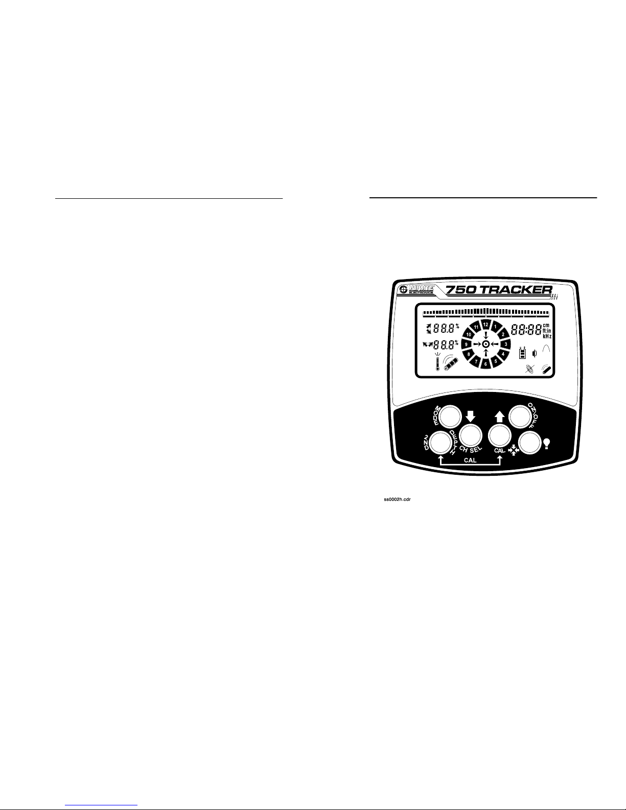
CONTROLS
OVERVIEW
The 750 Tracker performs well with a variety of beacons and can
track shallow or deep bores. It can send beacon information to a
display mounted on the drilling unit operator’s station. The 750
Tracker can also locate lines and cables. Available modes are 8
kHz active (when used with transmitter) and 60 or 50 Hz passive
(for locating power cables).
A brief description of the buttons and display on the 750 Tracker
follows.

8
750 Tracker - CONTROLS
CONTROLS
8
750 Tracker - CONTROLS
CONTROLS
CONTROLS
On/Off
Pressing this button turns unit on and off.
Fore/Aft/Left/Right
Pressing this button while in walkover tracking
mode switches from fore/aft to left/right arrows.
Only one set of arrows will show at a time. See
OPERATION
for further information.
Up
Pressing this button raises gain (increases
signal).
Down
Pressing this button reduces gain (decreases
signal).
Depth
This button estimates depth of properly located signal source
when pressed. See
OPERATION
for information on locating
signals.
Mode
Pressing this button changes location mode and operating
frequency .

750 Tracker - CONTROLS
9
CONTROLS
750 Tracker - CONTROLS
9
CONTROLS
Depth + On/Off
Pressing these b utt ons when t rac ker is on cycles v olu me from lo w
to high to off. Pressing and holding depth button before turning
tracker on changes signal strength display. See “Signal Strength”
section later in this chapter for more information.
Depth + Fore/Aft/Left/Right
Pressing these buttons switches LCD backlight off and on.
Depth + Up
Pressing these buttons enters tracker into calibration mode. See
OPERATION
for further information.
Depth + Down
Pressing these buttons selects radio channel. “CH-1” or “CH-2” or
“OFF” will appear in display.
Depth + Mode
Pressing these buttons changes depth units from default setting
of feet:inches to inches, centimeters, or meters.
On + Up
Holding up button and pressing on button switches left/right
arrows off and on.
On + Down
Holding down button and pressing on button switches all
guidance arrows off and on. NOTE: If all arrows are disabled,
remote guidance will not work.

10
750 Tracker - CONTROLS
CONTROLS
10
750 Tracker - CONTROLS
CONTROLS
Fore/Aft/Left/Right + Mode
Pressing these buttons starts tracker control code transmission
(see
OPERATION
).
Fore/Aft/Left/Right + On/Off
Pressing these buttons advances first two digits of tracker control
code (see
OPERATION
).
Fore/Aft/Left/Right + Depth
Pressing these buttons lowers first two digits of tracker control
code (see
OPERATION
).
Fore/Aft/Left/Right + Up
Pressing these buttons advances last two digits of tracker control
code (see
OPERATION
).
Fore/Aft/Left/Right + Down
Pressing these buttons lowers last two digits of tracker control
code (see
OPERATION
).

750 Tracker - CONTROLS
11
SETUP
750 Tracker - CONTROLS
11
SETUP
SETUP
Install batteries
Use 6 C-cell alkaline batteries in
tracker. To install:
• unscrew battery cover
• insert batter ie s as ind icate d
• close cover and tighten screw
• check operation
Check Operation
Always check that tracker operates before leaving for jobsite and
after every battery change. To check operation:
• turn on tracker
• entire display will light briefly
• battery level will be shown graphically
• unit defaults to 29 kHz mode
12
750 Tracker - CONTROLS
DISPLAY
12
750 Tracker - CONTROLS
DISPLAY
DISPLAY
Mode
Tracker can track beacons and locate lines. Switch between
modes by pressing mode button.
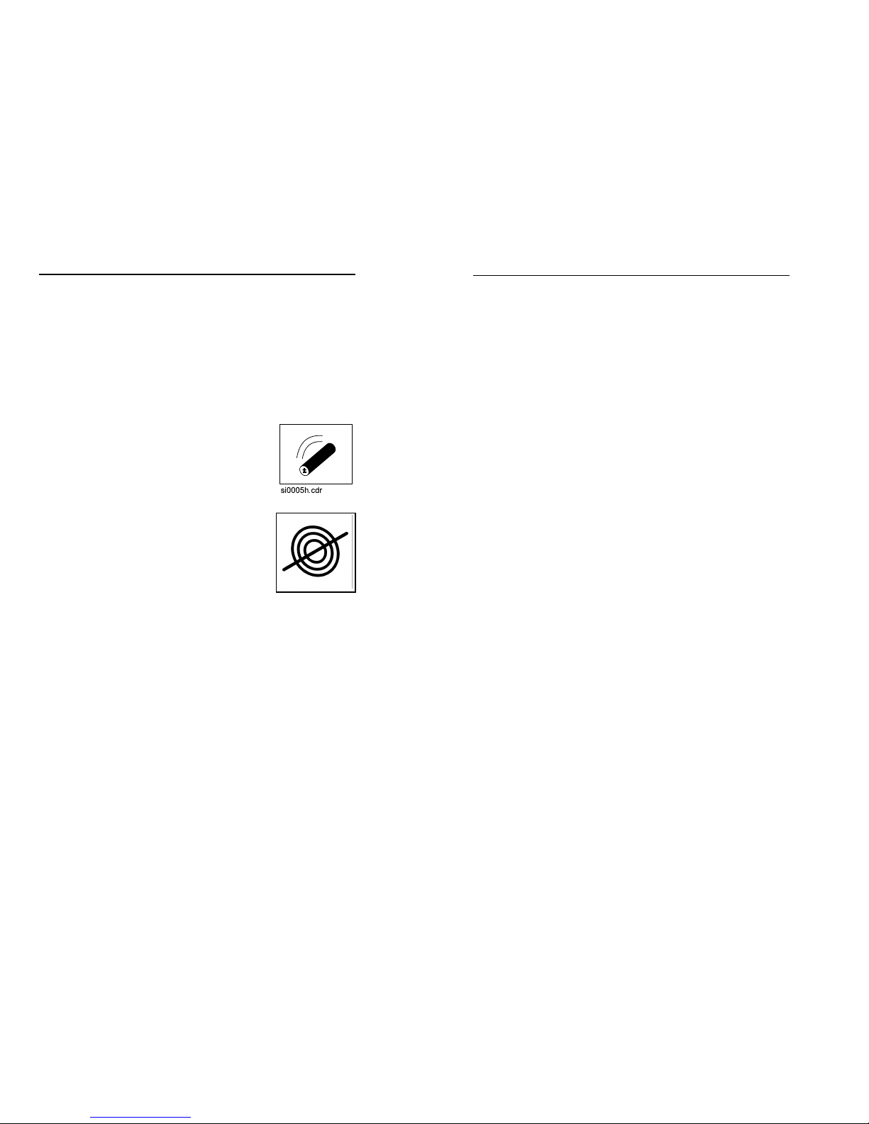
Beacon Mode Indicator
Line Mode Indicator
750 Tracker - CONTROLS
13
DISPLAY
750 Tracker - CONTROLS
13
DISPLAY
Tracker Information
A variety of tracker information can be monitored in the display
window. Additionally, several tracker display settings can be
changed.
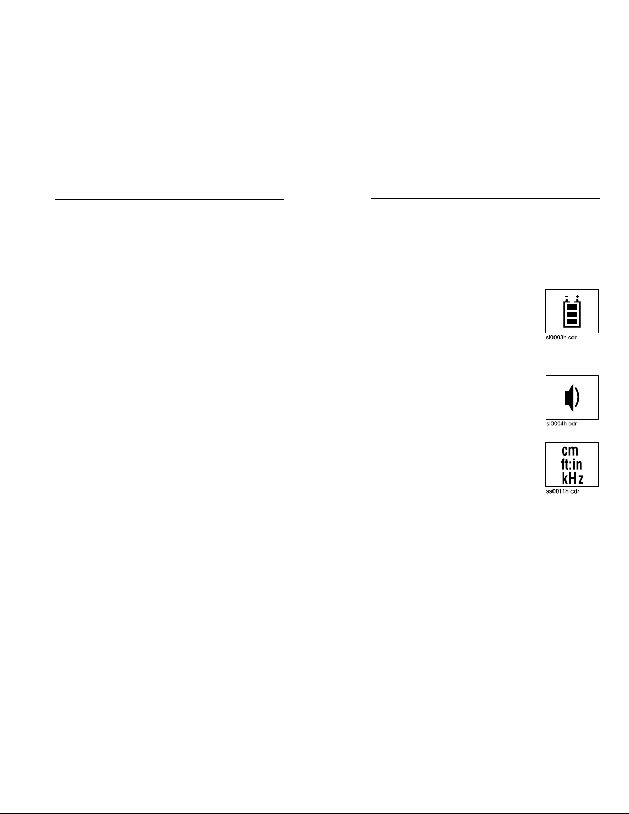
Battery Level
Tracker battery level is shown graphically.
Display shows battery status in 33% steps.
When tracker battery drops below 10%, tracker
battery symbol outlin e flashes. Replac e
batteries immediately.
Volume Level
Speaker volume can be adjusted by pressing
the depth and on/off buttons. Available settings
are low, high and off.
Depth Units
Depth estimates can be displayed in four ways:
feet:inches, inches, centimeters, or meters. To
change depth units, press depth and mode
buttons.
 Loading...